US1851050A - Condensing system - Google Patents
Condensing system Download PDFInfo
- Publication number
- US1851050A US1851050A US412762A US41276229A US1851050A US 1851050 A US1851050 A US 1851050A US 412762 A US412762 A US 412762A US 41276229 A US41276229 A US 41276229A US 1851050 A US1851050 A US 1851050A
- Authority
- US
- United States
- Prior art keywords
- water
- pump
- condenser
- compartments
- water box
- Prior art date
- Legal status (The legal status is an assumption and is not a legal conclusion. Google has not performed a legal analysis and makes no representation as to the accuracy of the status listed.)
- Expired - Lifetime
Links
Images
Classifications
-
- F—MECHANICAL ENGINEERING; LIGHTING; HEATING; WEAPONS; BLASTING
- F28—HEAT EXCHANGE IN GENERAL
- F28B—STEAM OR VAPOUR CONDENSERS
- F28B9/00—Auxiliary systems, arrangements, or devices
- F28B9/04—Auxiliary systems, arrangements, or devices for feeding, collecting, and storing cooling water or other cooling liquid
-
- Y—GENERAL TAGGING OF NEW TECHNOLOGICAL DEVELOPMENTS; GENERAL TAGGING OF CROSS-SECTIONAL TECHNOLOGIES SPANNING OVER SEVERAL SECTIONS OF THE IPC; TECHNICAL SUBJECTS COVERED BY FORMER USPC CROSS-REFERENCE ART COLLECTIONS [XRACs] AND DIGESTS
- Y10—TECHNICAL SUBJECTS COVERED BY FORMER USPC
- Y10S—TECHNICAL SUBJECTS COVERED BY FORMER USPC CROSS-REFERENCE ART COLLECTIONS [XRACs] AND DIGESTS
- Y10S165/00—Heat exchange
- Y10S165/092—Heat exchange with valve or movable deflector for heat exchange fluid flow
- Y10S165/101—Heat exchange with valve or movable deflector for heat exchange fluid flow for controlling supply of heat exchange fluid flowing between hydraulically independent heat exchange sections
Definitions
- My invention relates I to condensing/systems and particularly to water circulating.
- Fig. 1 is a View, partly in section and partly in elevatlon, of" one form of condensmg sys-- tem arranged inaccordanc'e wlthmy 1nven-' tion; and
- one pump may supply circulating water not only to its own associated group of tubes, but also to the tubes ordinarily associated with the inactive pump.
- a single pump may be utilized to circulate water through the entire tube nest and, the vacuum obtained, which possibly may not be as good as when both pumps are employed, is better than if the single active pump supplied water to only a portion of the tube nest.
- valves and piping for interconnecting the circulating pumps is not always desirable because ofthe cost thereof, the space occupied, the weight to be supported and the fact that the use of the interconnection is only periodic and temporary. This can be better appreciated when it is taken into consideration that cross-connecting pipes and valves of this character may be of the order of in diameter.
- a valve structure arranged to control the flow of water through the opening or openings and between the compartments.
- a condenser 10 embodying a shell structure 11, tube sheets 12, an inlet water box 13 and a discharge water box 14. Extending between the tube sheets 12 is a nest of cooling tubes 15 through which the cooling water passes in a single longitudinal direction from the inlet water box 13 to the outlet water box 14.
- I have shown a condenser of the single-pass type, but it is to be understood, as will be apparent from the following description, that my invention is equally applicable to condensers of the multipass type.
- Embodied in the inlet water box 13 is a vertically-extending partition 16 which divides the water box into two separate compartments 17 and 18.
- the discharge water box 14 is provided with a partition 19 which divides the outlet water box into compartments 22 and 23. Included in the compartments 17 and 18 of the inlet water box are respective inlets 24 and 25 while the compartments 22 and 23 of the outlet water box have separate outlets 26 and 27.
- Cooling water is supplied to the condenser by means of suitable pumps 28 and 29 driven by suitable motors 31.
- the pumps illustrated are of the propeller type and each'is provided with an inlet connection 32 for removing water from an intake tunnel ofthe power plant (not shown) and for discharging the same through an outlet 33.
- the outlets 33 connect, respectively, by means of suitable stop valves 34 and expansion joints 35, with the inlets 24 and 25 of the inlet water box 13.
- the pump 28 is therefore arranged to supply water to the compartment 17 of the inlet water box and the group of tubes associated therewith, while the pump 29 supplies water to the compartment 18 and its associated tubes.
- I provide, in the partition 16, an opening 36 arranged to be covered and uncovered by some means such as, for example, a slide valve 37 movable in a suitable guideway 38 disposed within the water box and carried by the partition wall 16.
- the slide valve 37 may be moved to cover and uncover the opening 36 by means of various types of operating gears.
- a rack 39 is provided, which rack meshes with a pinion 41.
- the latter is connected to an operating shaft 42 which projects outside of the water box and to which an operating hand wheel 43 may be attached.
- the shaft 42 is preferably supported in bearings 44 and 45 forming a part of the guideway structure of the valve and, in order that a fluid-tight joint may be maintained where the operating shaft passes through the wall of the water box, a suitable stutfing box 46 is provided.
- a suitable stutfing box 46 is provided in order to permit access to the interior of either compartments of the inlet water box 13, the latter is provided with separate, independently removable covers 47 and 48.
- the valve 37 is closed, the pump 29 is stopped, and the cover 48 is removed. At such times, the pump 28 continues tocirculate water between the compartments 17 and 22 of the inlet and outlet water boxes. As the valve 37 is in a closed position, the water circulates substantially through one-half of the tube nest, the condenser being continued in operation Without any interruptions whatsoever.
- the pump 29 may supply cooling Water to the entire tube nest.
- a condensing system the combination of a surface condenser having a steam inlet and an inlet Water box divided by a partition into a pair of compartments, the partition extending in the general direction of the plane of the condenser and steam inlet axes, tWo separate and independent pumps for supplying partments When the other pump is isolated 7 from its compartment including valve means affording communication between the compartments and means extending exteriorly .of
Landscapes
- Engineering & Computer Science (AREA)
- Mechanical Engineering (AREA)
- General Engineering & Computer Science (AREA)
- Heat-Exchange Devices With Radiators And Conduit Assemblies (AREA)
Description
March 29, 1932. J. P. LIDIAK 1,851,050
CONDENSING SYSTEM Filed Dec. 9, 1929 WITNESSES: INVENTOR' V ga J-RLidiak- BY ATTORNEY Patented Mar. 29, 1932 UNITED" s r-ares; P TENT" osrice" I JOSEPH P. LIDIAK, or Lnnsnowivn, PENNSYLVANIA; Assreivon- To WESTINGHOUSE- ELEcTRIc afliunnunAcrunme COMPANY, A coRroRA'r-Ion OF-=;PENNSYLVAN-IA- oonnnivsnve SYSTEM,
Application-filed"December9; 1929." Seria1No.'412,762".'-'
My invention relates I to condensing/systems and particularly to water circulating.
systems for condensers of the'surface-type and still more particularly,- condensers of the 5 surface type provided with divided water boxes, that is, condensers wherein the 1 water 1 boxes are divided into two or more compartments separated by vertically-extendingpartition walls and wherein separate pumping: 1o apparatus is provided for the respective com-- partments, whereby water may be circulated through one portion of the :tube nest: of :the' condenser while another" portion 1 is beingizi cleaned.=
2o t-heir correspondingtube-nest portions in order that all, ornearly all,of the tube surface of the condenser may be made I available at such times as one of the pumpi'ngsystems'may be rendered temporarily inactiveu It has for a-furtherob valve or valves operated from outside ofthe condenser in order thatthe compartments of the water box may be placed in communica tionwith each other so that-two or more compartments may, at times, be supplied with 3 water from a single pumping system.
These and other objects are efi'ected bymy inventionas will be apparent from the following description and claim taken in connection with the accompanying drawings form-i 40 mga part of this pp which:
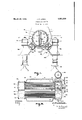
Fig. 1 is a View, partly in section and partly in elevatlon, of" one form of condensmg sys-- tem arranged inaccordanc'e wlthmy 1nven-' tion; and
Fig. 2 is aplanlview, in section, of the same' ect to provide a system of theforegoing character wherein-= the partition or partitions within the water box are provided with opening; or openings. arranged to be covered and uncoveredby a place, the vacuumproduced'by the con'den'se 7 condensing system 1 taken" on" the line II- 11 r of Fig. 1.
It is the general practice to"provide-con densers of "the larger capacities "with "water boxes which are divided into =two 'or more separate compartments',- each compartment having ia separate water circulating 'systen'i or pump associated therewith: By means of such an arrangement," the 1 tube nest 'of -the condenser may "be cleaned without 1 inter- '5 rupting thewor'kingiof the condenser. This 1 is readily effected by shutting'down'oneofthe circulating pumps, openingup its connectih'gf I water box compartment and I cleaning the tubes of the nest associated with the 'opened" water-"box compartment. During the clean 'ing' process, the other pump or pumps con-' tinue to operate and: circulate water-through the remainder ot the tube nest; that is, the tubes which are not-being cleaned:
When the cleaning of the first' group been completed','the water is againcircul'ated therethrough and: the a circulation of water through another grlo up is interrupted? By' working 1 upon 1 the respective groups "of tubes' in such sequence, the entire tube nest may be cle'anedwithout any interruption in the oper'-" ation 1 of the condenser;- Of coursegduringzr the time when such cleaning process is-taking may be somewhat impaired' owing-to the hea a nest. It sometimeshappens'that one of the cir culatingipumps mayrequire overhauling and,
as-a consequenceg the portion of: thetubene'st associated therewith receives no circulatingx water while the pump is beingworkedhpona Atsuch times, the condenser may be'operated by circulating water through the remainder of the tube nest, in the same manner as when the tube cleaningprocess is underway. How-* ever, here again, the vacuum is a'fiected"some what cletri-mentally and it ha's' therefore been proposed to interconnectthepumps so'-that,
in times of emergency, or, with water at low temperature, one pump may supply circulating water not only to its own associated group of tubes, but also to the tubes ordinarily associated with the inactive pump. In this way, a single pump may be utilized to circulate water through the entire tube nest and, the vacuum obtained, which possibly may not be as good as when both pumps are employed, is better than if the single active pump supplied water to only a portion of the tube nest.
The provision of suitable valves and piping for interconnecting the circulating pumps is not always desirable because ofthe cost thereof, the space occupied, the weight to be supported and the fact that the use of the interconnection is only periodic and temporary. This can be better appreciated when it is taken into consideration that cross-connecting pipes and valves of this character may be of the order of in diameter.
I have therefore conceived the idea of providing an opening or openings in the partition which separates the inlet water box into separate compartments and of embodying, in the water box, a valve structure arranged to control the flow of water through the opening or openings and between the compartments. In this way, only a single valve of simple structure is required, which valve is located inside of the water box and out of the way, and the requirement for considerable piping, valves, T-fittings, elbows, etc., is entirely dispensed with.
Referring now to the drawings, I show a condenser 10 embodying a shell structure 11, tube sheets 12, an inlet water box 13 and a discharge water box 14. Extending between the tube sheets 12 is a nest of cooling tubes 15 through which the cooling water passes in a single longitudinal direction from the inlet water box 13 to the outlet water box 14. In the present embodiment, I have shown a condenser of the single-pass type, but it is to be understood, as will be apparent from the following description, that my invention is equally applicable to condensers of the multipass type.
Embodied in the inlet water box 13 is a vertically-extending partition 16 which divides the water box into two separate compartments 17 and 18. Likewise, the discharge water box 14 is provided with a partition 19 which divides the outlet water box into compartments 22 and 23. Included in the compartments 17 and 18 of the inlet water box are respective inlets 24 and 25 while the compartments 22 and 23 of the outlet water box have separate outlets 26 and 27.
Cooling water is supplied to the condenser by means of suitable pumps 28 and 29 driven by suitable motors 31. The pumps illustrated are of the propeller type and each'is provided with an inlet connection 32 for removing water from an intake tunnel ofthe power plant (not shown) and for discharging the same through an outlet 33. The outlets 33 connect, respectively, by means of suitable stop valves 34 and expansion joints 35, with the inlets 24 and 25 of the inlet water box 13. At this time it is noted that while, in the present embodiment, I show pumps of the propeller type, it will be apparent that my invention applies equally to condensing systems wherein pumps of other types are employed.
The pump 28 is therefore arranged to supply water to the compartment 17 of the inlet water box and the group of tubes associated therewith, while the pump 29 supplies water to the compartment 18 and its associated tubes. In order that either pump may supply water'to the entire tub-e nest, I provide, in the partition 16, an opening 36 arranged to be covered and uncovered by some means such as, for example, a slide valve 37 movable in a suitable guideway 38 disposed within the water box and carried by the partition wall 16. The slide valve 37 may be moved to cover and uncover the opening 36 by means of various types of operating gears. In the present embodiment, a rack 39 is provided, which rack meshes with a pinion 41. The latter,.in turn, is connected to an operating shaft 42 which projects outside of the water box and to which an operating hand wheel 43 may be attached. The shaft 42 is preferably supported in bearings 44 and 45 forming a part of the guideway structure of the valve and, in order that a fluid-tight joint may be maintained where the operating shaft passes through the wall of the water box, a suitable stutfing box 46 is provided. In order to permit access to the interior of either compartments of the inlet water box 13, the latter is provided with separate, independently removable covers 47 and 48.
From the foregoing description, the operation of my improved condensing system will be apparent. Assuming that the system is operating under normal conditions, the pump 28 supplies cooling water to the inlet 24 and the pump 29 supplies cooling water to the inlet 25. At such times, it does not matter whether the valve 37 covers or uncovers the opening 36. The water-flows through the nest of tubes and enters the compartments 22 and 23 of the outlet water box from which it is discharged through the outlets 26 and 27.
Assuming that it is desired to clean the condenser tubes, the valve 37 is closed, the pump 29 is stopped, and the cover 48 is removed. At such times, the pump 28 continues tocirculate water between the compartments 17 and 22 of the inlet and outlet water boxes. As the valve 37 is in a closed position, the water circulates substantially through one-half of the tube nest, the condenser being continued in operation Without any interruptions whatsoever.
After the tubes associated With the compartments 18 and 23 have been cleaned, Water is again circulated through these tubes by the pump 29 While the pump 28 is stopped and cleaning of the tubes associated With the compartments 17 and 22 is proceeded With. In this Way, the entire tube nest of the condenser may be cleaned Without interrupting its operation.
Assuming that it is desired to overhaul one of the pumps, for example, the pump 29, this may be readily effected by shutting its associated valve 34, thus isolating the pump from the condenser, At such times, the hand Wheel 43 is actuated to move the valve 37 to uncover the opening 36 so that the circulating pump 28 is capable of supplying the Water to both compartments 17 and 18 of the inlet Wat-er box. As a result, the pump 28 supplies cooling Water to the entire tube nest of the condenser, thus rendering the latter highly effective even though one of its circulating pumps is temporarily disabled. It will be apparent that, should it be necessary at any time to overhaul the pump 28 rather than the pump 29, the arrangement is such that the pump 29 may supply cooling Water to the entire tube nest.
From the foregoing, it Will be apparent that I have evolved a form of condensing system Which is especially adapted for condensers of the larger capacities and Which provides for a highly flexible method of operation in that not only may the tubes of the condenser be cleaned While the condenser is in operation, but the entire tube surface of the condenser may be rendered available during such times as one of the circulating pumps is inactive. My arrangement has the further advantage that, during periods of light loads, either one of the pumps may supply the required cooling Water to the entire condenser tube nest merely by opening the valve 37 It Will be obvious that all of this is accomplished at very little expense merely by providing a single valve of simple structure in the inlet Water box.
While I have shown my invention in but one form, it Will be obvious to those skilled in the art that it is not so limited, but is susceptible of various changes and modifications, Without departing from the spirit thereof, and I desire, therefore, that only such limitations shall be placed thereupon as are imposed by the prior art or as are specifically set forth in the appended claim.
' What I claim is In a condensing system, the combination of a surface condenser having a steam inlet and an inlet Water box divided by a partition into a pair of compartments, the partition extending in the general direction of the plane of the condenser and steam inlet axes, tWo separate and independent pumps for supplying partments When the other pump is isolated 7 from its compartment including valve means affording communication between the compartments and means extending exteriorly .of
the condenser for operating the valve means.
. In testimony whereof, I have hereunto subscribed my name this 29th day of Nov., 1929.
JOSEPH P. LIDIAK.
Priority Applications (1)
| Application Number | Priority Date | Filing Date | Title |
|---|---|---|---|
| US412762A US1851050A (en) | 1929-12-09 | 1929-12-09 | Condensing system |
Applications Claiming Priority (1)
| Application Number | Priority Date | Filing Date | Title |
|---|---|---|---|
| US412762A US1851050A (en) | 1929-12-09 | 1929-12-09 | Condensing system |
Publications (1)
| Publication Number | Publication Date |
|---|---|
| US1851050A true US1851050A (en) | 1932-03-29 |
Family
ID=23634380
Family Applications (1)
| Application Number | Title | Priority Date | Filing Date |
|---|---|---|---|
| US412762A Expired - Lifetime US1851050A (en) | 1929-12-09 | 1929-12-09 | Condensing system |
Country Status (1)
| Country | Link |
|---|---|
| US (1) | US1851050A (en) |
-
1929
- 1929-12-09 US US412762A patent/US1851050A/en not_active Expired - Lifetime
Similar Documents
| Publication | Publication Date | Title |
|---|---|---|
| US1851050A (en) | Condensing system | |
| US2966779A (en) | Heating and cooling system for motor yachts | |
| US3633658A (en) | Combination hot condensate cooling and water heating and storage and delivery system | |
| US2164605A (en) | Radiator bypass device | |
| US1730736A (en) | Hot-water system | |
| JP3623920B2 (en) | Cargo tank cleaning and hot water heating system | |
| US1753955A (en) | Condenser | |
| WO2010002267A1 (en) | Cooling system for floating vessel | |
| US1038200A (en) | Means for cooling turbo compressors or blowers. | |
| US2053142A (en) | Temperature regulating system for vapor electric devices | |
| US1406815A (en) | Compartment surface condenser | |
| US2287958A (en) | Heat exchange apparatus | |
| JP2001082770A (en) | Cooling equipment system | |
| US1153233A (en) | Hot-water-circulating system. | |
| US2978880A (en) | Steam vacuum refrigeration unit | |
| KR20150121309A (en) | Bilge system for ship improved starting pumping time | |
| US1845548A (en) | Condenser water circulating system | |
| US1733179A (en) | Cooling apparatus for electrical machines | |
| US1854288A (en) | Condensing system | |
| SU1709467A1 (en) | Oil bath for thrust bearing of hydraulic-turbine generator | |
| US938061A (en) | Freezing-plate. | |
| US3050962A (en) | Centrifugal compressor and heat exchanger unit | |
| US1065442A (en) | Apparatus for treating and storing water. | |
| US1804936A (en) | System of heat interchange | |
| US20170133113A1 (en) | Nuclear reactor structure |