US1850178A - Vise - Google Patents
Vise Download PDFInfo
- Publication number
- US1850178A US1850178A US509676A US50967631A US1850178A US 1850178 A US1850178 A US 1850178A US 509676 A US509676 A US 509676A US 50967631 A US50967631 A US 50967631A US 1850178 A US1850178 A US 1850178A
- Authority
- US
- United States
- Prior art keywords
- vise
- jaw
- clamp
- lugs
- channel
- Prior art date
- Legal status (The legal status is an assumption and is not a legal conclusion. Google has not performed a legal analysis and makes no representation as to the accuracy of the status listed.)
- Expired - Lifetime
Links
Images
Classifications
-
- B—PERFORMING OPERATIONS; TRANSPORTING
- B25—HAND TOOLS; PORTABLE POWER-DRIVEN TOOLS; MANIPULATORS
- B25B—TOOLS OR BENCH DEVICES NOT OTHERWISE PROVIDED FOR, FOR FASTENING, CONNECTING, DISENGAGING, OR HOLDING
- B25B1/00—Vices
- B25B1/24—Details, e.g. jaws of special shape, slideways
- B25B1/2484—Supports
-
- B—PERFORMING OPERATIONS; TRANSPORTING
- B25—HAND TOOLS; PORTABLE POWER-DRIVEN TOOLS; MANIPULATORS
- B25B—TOOLS OR BENCH DEVICES NOT OTHERWISE PROVIDED FOR, FOR FASTENING, CONNECTING, DISENGAGING, OR HOLDING
- B25B1/00—Vices
- B25B1/06—Arrangements for positively actuating jaws
- B25B1/10—Arrangements for positively actuating jaws using screws
- B25B1/103—Arrangements for positively actuating jaws using screws with one screw perpendicular to the jaw faces, e.g. a differential or telescopic screw
Definitions
- i evi e tm y be d as at ⁇ ; ld engjm ene reeti eeet b ri b e d...t e d vi e rigid y in pos ti t e.
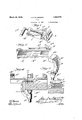
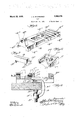
- My invention is illustreted more or less diagrammatically in the accompanying drew-l ings, whereinf 1 "F g e 1 is a Per pe e t p v e 1 F gu e 2 s iatper peeti bo om i iew; F u Bid eper'ep e i e f e cla p; Figure 4 is tJe tudin lee iQ e
- Figure 5 is a seotion along the line 5+ -5 of Eigu F gure .45 eip repectiv r i.
- e is the fixed yise a jaw.
- the fixed jaw is moved to the back end of the pad.
- the lead screw does not need to be long enough to carry the movable jaw clear to the back end of the pad.
- the key is withdrawn, the fixed aw is moved back or forward as the case may be and the key replaced.
- 0 is the movable vise jaw. It is adapted to fit over the pad A having downwardly extending walls C with flanges C for that pur pose.
- C is a socket in the center of the jaw.
- C is the lead screw having a spherical head C to engage the conical bottom C of the hole The end of the screw is G in the hub C slotted as indicated at C and the pin C passing downwardly through the hubengages this slot and holds the lead screw against displacement with respect to thejaw while not interfering at all with its rotary movement.
- the lead screw is threaded in the boss'A and terminates in a handle C by which it may be manipulated.
- the clamp D is a clamp. It has at one end a nut D which is threaded to the clamp screw D which screw carries a support engaging head D
- the other end of the clamp is provided with an enlarged head D this head having two opposed slots D closed at the end furthest removed from the body of the clamp as at D and open at the other end; These slots are adapted to be penetrated by the lugs A to hold the clamp and jaw body in engagement.
- the dimensions of the parts are such as shown in Figure 4 that when the clamp is in engagement with the lugs A the clamp itself, that is the part which extends horizontally or parallel with the vise body is altogether inside the contour of the vise body and clear of the surface upon which the vise is mounted.
- This clamp may be engaged with the vise either from the right hand or from the left as shown in Figures 4 and 9.
- the pad A terminates far enough away from the lug A to permit disengagement of the sliding jaw from the pad by moving it toward the lug A and pulling out the lead screw and lifting it upwardly in a direction generally perpendicular to the pad'A so that it is not necessary to remove the fixed jaw to separate the moving jaw from the vise body.
- a clamp comprising a clamp body, an integral saddle thereon projecting laterally from both sides of the body adjacent its top, a fixed jaw at one end of the clamp body, bounding one end of the saddle, a threaded lead screw lug projecting upwardly from the opposed end of the body, the sliding jaw carrier adapted to engage the saddle and slide therealong, the movable jaw carried thereby, there being a clearance between the end of the saddle and the lead screw lug greater than the length of the sliding carrier whereby the carrier may be moved 01f the saddle for disengagement.
- a vise body of channel cross section lugs projecting inwardly in opposition one to the other from the opposed walls of the channel, a clamp adapted to penetrate the channel from either end thereof and interlock with the lugs.
- a vise body of channel cross section lugs projecting inwardly in opposition one to the other from the opposed walls of the channel, a clamp adapted to penetrate the channel from either end thereof and interlocked with the lugs, the clamp comprising a head adapted to lie in general parallelism with the vise body, slots on opposed sides of the head adapted to engage the lugs.
- a vise body of channel cross section lugs projecting inwardly in opposition one to the other from the opposed walls of the channel, a clamp adapted to penetrate the channel from either end thereof and interlocked with the lugs, the clamp comprising a head adapted to lie in general parallelism with the vise body, slots on'opposed sides of the head adapted to engage the lugs, the slots being closed at one end.
- a vise body of channel cross section lugs projecting inwardly in opposition one to the other from the opposed Walls of the channel, a clamp adapted to penetrate the channel from either end thereof and interlocked with the lugs, the clamp comprising a head adapted to lie in general parallelism with the vise body, slots on opposed sides of the head adapted to engage the lugs, the slots being closed at the end furthest removed from the body of the clamp.
- a vise body In a vise, a vise body, a plate carried thereby and projecting on opposed sides therebeyond, a jaw interlocking with the plate and adapted to slide along the body, a stop projecting upwardly from the body at a point removed from the plate, the jaw being of such Width that when in immediate proximity to the stop it may be disengaged from the plate and removed from the body.
- a vise body a plate carried thereby and projecting on opposed sides therebeyond, a jaw interlocking with the plate and adapted to slide along the body, a stop projecting upwardly from the body at a point removed from the plate, the jaw being of such width that when in immediate proximity to the stop it may be disengaged from the plate and removed from the body, a. second jaw slidable along the plate and means for independently adjustably locking it in opposition to the first jaw.
- a vise body a vise body, a plate carried thereby and projecting on opposed sides therebeyond, a jaw interlocking with the plate and adapted to slide along the body, a
- V 1 means for independently ad ustably locking 7 it in opposition to the first jaw, said means including a key adapted to penetrate the jaw and lie in channels spaced along the upper surface of the late.
Landscapes
- Engineering & Computer Science (AREA)
- Mechanical Engineering (AREA)
- Gripping Jigs, Holding Jigs, And Positioning Jigs (AREA)
Description
March 22, 1932. .15, MCCHE NEY 1,850,178
VISE
' Filed Jan. 19, 1931 2 Sheets-Sheet l March '22, 1932. J, 5, MOC'HESNEV 1,850,178
' VISE Filed Jan. 19, l931 2 Sheets-Sheet 2 Patented I Mar. 22 1932 1. Application .flled" J anuaryu19, 1931. Y es eriat- INo. :.50 9;676;
eeetbre gbl rheidj i l lpie i endeen e e. t e ye f t r w e The i evi e tm y be d as at}; ld engjm ene reeti eeet b ri b e d...t e d vi e rigid y in pos ti t e. meunteble elemp m y e u ediendbb e el t p m ycbeeng g wi e i edi e h 0 the eie y be ei e e e vee ide' ren e Pe i ie s e d Wedieetm n to 1 W llb m eild tbi reenn ti n h t c use the und si e Let t e r s itsel reet g en, t e u fa f, and he t iwn a ains it by t e-elem, t e elemp end t e ri e eepe e e felrm rig deunit y s r e ure whi bi ightened niple e y het ghten gup tet l p serewiint-ucontrast Qwiththe ,cvenven iona arrangement ewherei the-clamp. isi-sexparately.
fastened-end; theise is-.separate1y.mounted 011 the clamp and two separgrteitightening actions combine with opportunity for-play and misalignment enter in, I
I My invention is illustreted more or less diagrammatically in the accompanying drew-l ings, whereinf 1 "F g e 1 is a Per pe e t p v e 1 F gu e 2 s iatper peeti bo om i iew; F u Bid eper'ep e i e f e cla p; Figure 4 is tJe tudin lee iQ e Figure 5 is a seotion along the line 5+ -5 of Eigu F gure .45 eip repectiv r i. t e'Y e-be e wi htheethe rpelts'remov down niove nent, when in engegernent ilre Th s wpe spe tiveef; the fix dfli J F gu e :8 s ,.:perspee ir -.e -,t e mere'b Figure 9 is alongitudinal geetion einiilan F Fi u e 6 owi g ezever el gzhle mg eeh niemi w i i epart s are illusti'etedby like s arts throughout the epeoifioetion au;1d dray mjgs. .A: et e lempb e -l It; i el t d; ii edereide r nd et de Atetfit efifl itis of channel section. The two down we r y ext nd ne e t e ehepne h tee h e dtW- .rd y=pr ie tieeibe e MN- lntegral with the body; is thepad A? which r d pr je t .eut erd yenbe b e-b ic nd t We Aien ;r2 d i i h e i e t n ver e is et n t e IuPiP- e tl e 'l heueentral portion of thmp ad end-bodjiiis aperturedas indicated at- A iA lAtere ampin le s r i e i g nwerd yuentfe posed sides of the aperture A from the walls A- .The i e gee sh w e e im n fure 2 terminate ab eye the lower vextremities of the allsieoeetQ be entirelyput of Contac wi e yte r e i-up i vh hntl ne r t- T e e p 1 1'e -,=l ibt xci yIiir t b d a d s ee ed e e temi eng ge the vise lead screw.
e is the fixed yise a jaw. ,At either end h re f. e e d wa d yvde eml we ls adapted to engage the outer walls of .thepad A 1. a d; bbe We s r ina e i i ward extending guide 1ugs B? which penetrate beneath the pad Ainterlocking with it hold he fixe i -Wege n t-t enev ei ?i 11 3 r e. ape t es. thr u h he b dv'i e th jaw xtend dnthe Wall 1 e e which v extends plear through the jaw ena in t e eperter eBFendi e i le A? me old e iew e a usted pee t e .e e vth pat JThfiQfidiQfil-T'QEQ? iemede nce-ens? f the w adjustm nt r: th eelemP gm ti n bei g ot efie t dsbyai 1 t. s;- eper ur d to make it possible to use a relatively short lead screw. For wide openings of the vise, the fixed jaw is moved to the back end of the pad. The lead screw does not need to be long enough to carry the movable jaw clear to the back end of the pad. When it is desired to make a quick adjustment of the opening of the vise, the key is withdrawn, the fixed aw is moved back or forward as the case may be and the key replaced.
0 is the movable vise jaw. It is adapted to fit over the pad A having downwardly extending walls C with flanges C for that pur pose. C is a socket in the center of the jaw. C is the lead screw having a spherical head C to engage the conical bottom C of the hole The end of the screw is G in the hub C slotted as indicated at C and the pin C passing downwardly through the hubengages this slot and holds the lead screw against displacement with respect to thejaw while not interfering at all with its rotary movement. The lead screw is threaded in the boss'A and terminates in a handle C by which it may be manipulated.
D is a clamp. It has at one end a nut D which is threaded to the clamp screw D which screw carries a support engaging head D The other end of the clamp is provided with an enlarged head D this head having two opposed slots D closed at the end furthest removed from the body of the clamp as at D and open at the other end; These slots are adapted to be penetrated by the lugs A to hold the clamp and jaw body in engagement. The dimensions of the parts are such as shown in Figure 4 that when the clamp is in engagement with the lugs A the clamp itself, that is the part which extends horizontally or parallel with the vise body is altogether inside the contour of the vise body and clear of the surface upon which the vise is mounted. This clamp may be engaged with the vise either from the right hand or from the left as shown in Figures 4 and 9.
It will be noted that the pad A terminates far enough away from the lug A to permit disengagement of the sliding jaw from the pad by moving it toward the lug A and pulling out the lead screw and lifting it upwardly in a direction generally perpendicular to the pad'A so that it is not necessary to remove the fixed jaw to separate the moving jaw from the vise body.
I claim:
1. A clamp comprising a clamp body, an integral saddle thereon projecting laterally from both sides of the body adjacent its top, a fixed jaw at one end of the clamp body, bounding one end of the saddle, a threaded lead screw lug projecting upwardly from the opposed end of the body, the sliding jaw carrier adapted to engage the saddle and slide therealong, the movable jaw carried thereby, there being a clearance between the end of the saddle and the lead screw lug greater than the length of the sliding carrier whereby the carrier may be moved 01f the saddle for disengagement.
2. In a vise, a vise body of channel cross section, lugs projecting inwardly in opposition one to the other from the opposed walls of the channel, a clamp adapted to penetrate the channel from either end thereof and interlock with the lugs.
In a vise, a vise body of channel cross section, lugs projecting inwardly in opposition one to the other from the opposed walls of the channel, a clamp adapted to penetrate the channel from either end thereof and interlocked with the lugs, the clamp comprising a head adapted to lie in general parallelism with the vise body, slots on opposed sides of the head adapted to engage the lugs.
4. In a vise, a vise body of channel cross section, lugs projecting inwardly in opposition one to the other from the opposed walls of the channel, a clamp adapted to penetrate the channel from either end thereof and interlocked with the lugs, the clamp comprising a head adapted to lie in general parallelism with the vise body, slots on'opposed sides of the head adapted to engage the lugs, the slots being closed at one end.
5. In a vise, a vise body of channel cross section, lugs projecting inwardly in opposition one to the other from the opposed Walls of the channel, a clamp adapted to penetrate the channel from either end thereof and interlocked with the lugs, the clamp comprising a head adapted to lie in general parallelism with the vise body, slots on opposed sides of the head adapted to engage the lugs, the slots being closed at the end furthest removed from the body of the clamp.
6. In a vise, a vise body, a plate carried thereby and projecting on opposed sides therebeyond, a jaw interlocking with the plate and adapted to slide along the body, a stop projecting upwardly from the body at a point removed from the plate, the jaw being of such Width that when in immediate proximity to the stop it may be disengaged from the plate and removed from the body.
7. In a vise, a vise body, a plate carried thereby and projecting on opposed sides therebeyond, a jaw interlocking with the plate and adapted to slide along the body, a stop projecting upwardly from the body at a point removed from the plate, the jaw being of such width that when in immediate proximity to the stop it may be disengaged from the plate and removed from the body, a. second jaw slidable along the plate and means for independently adjustably locking it in opposition to the first jaw.
8. In a vise, a vise body, a plate carried thereby and projecting on opposed sides therebeyond, a jaw interlocking with the plate and adapted to slide along the body, a
SCI
v a second jaw slidable alon V 1 means for independently ad ustably locking 7 it in opposition to the first jaw, said means including a key adapted to penetrate the jaw and lie in channels spaced along the upper surface of the late.
Signed at hicago, county of Cook and State of Illinois, this 15th day of January,
JOHN S. MOCHES'NEY.
Priority Applications (1)
| Application Number | Priority Date | Filing Date | Title |
|---|---|---|---|
| US509676A US1850178A (en) | 1931-01-19 | 1931-01-19 | Vise |
Applications Claiming Priority (1)
| Application Number | Priority Date | Filing Date | Title |
|---|---|---|---|
| US509676A US1850178A (en) | 1931-01-19 | 1931-01-19 | Vise |
Publications (1)
| Publication Number | Publication Date |
|---|---|
| US1850178A true US1850178A (en) | 1932-03-22 |
Family
ID=24027639
Family Applications (1)
| Application Number | Title | Priority Date | Filing Date |
|---|---|---|---|
| US509676A Expired - Lifetime US1850178A (en) | 1931-01-19 | 1931-01-19 | Vise |
Country Status (1)
| Country | Link |
|---|---|
| US (1) | US1850178A (en) |
Cited By (11)
| Publication number | Priority date | Publication date | Assignee | Title |
|---|---|---|---|---|
| US2493127A (en) * | 1944-07-15 | 1950-01-03 | Imp Brass Mfg Co | Tool for expanding and sizing the ends of metallic tubes |
| US4544135A (en) * | 1982-04-29 | 1985-10-01 | Dolphin Titan International, Inc. | Rig skidding system |
| US5277058A (en) * | 1992-11-23 | 1994-01-11 | Kalyon Dilhan M | Adjustable gap rheometer |
| WO1996007511A1 (en) * | 1994-09-02 | 1996-03-14 | Chick Machine Tool, Inc. | Apparatus for expanding the worksurface of a vise-like workholding apparatus |
| EP0889278A1 (en) * | 1997-07-02 | 1999-01-07 | Virax S.A. | Device for securing an object to the edge of a planar surface, especially a worktool like a vice or same to a workbench |
| US8109494B1 (en) | 2006-09-01 | 2012-02-07 | Chick Workholding Solutions, Inc. | Workholding apparatus having a movable jaw member |
| US8336867B1 (en) | 2006-09-01 | 2012-12-25 | Chick Workholding Solutions, Inc. | Workholding apparatus having a detachable jaw plate |
| US8454004B1 (en) | 2006-09-01 | 2013-06-04 | Chick Workholding Solutions, Inc. | Workholding apparatus having a movable jaw member |
| US8573578B1 (en) | 2006-09-01 | 2013-11-05 | Chick Workholding Solutions, Inc. | Workholding apparatus |
| US9227303B1 (en) | 2006-09-01 | 2016-01-05 | Chick Workholding Solutions, Inc. | Workholding apparatus |
| US9352451B1 (en) | 2013-05-02 | 2016-05-31 | Chick Workholding Solutions, Inc. | Workholding apparatus |
-
1931
- 1931-01-19 US US509676A patent/US1850178A/en not_active Expired - Lifetime
Cited By (16)
| Publication number | Priority date | Publication date | Assignee | Title |
|---|---|---|---|---|
| US2493127A (en) * | 1944-07-15 | 1950-01-03 | Imp Brass Mfg Co | Tool for expanding and sizing the ends of metallic tubes |
| US4544135A (en) * | 1982-04-29 | 1985-10-01 | Dolphin Titan International, Inc. | Rig skidding system |
| US5634253A (en) * | 1992-10-01 | 1997-06-03 | Chick Machine Tool, Inc. | Apparatus for expanding the worksurface of a vise-like workholding apparatus |
| US5762326A (en) * | 1992-10-01 | 1998-06-09 | Chick Workholding Systems, Inc. | Apparatus for expanding the worksurface of a vise-like workholding apparatus |
| US5277058A (en) * | 1992-11-23 | 1994-01-11 | Kalyon Dilhan M | Adjustable gap rheometer |
| WO1996007511A1 (en) * | 1994-09-02 | 1996-03-14 | Chick Machine Tool, Inc. | Apparatus for expanding the worksurface of a vise-like workholding apparatus |
| EP0889278A1 (en) * | 1997-07-02 | 1999-01-07 | Virax S.A. | Device for securing an object to the edge of a planar surface, especially a worktool like a vice or same to a workbench |
| US5988615A (en) * | 1997-07-02 | 1999-11-23 | Virax S.A. | Device for fixing an object to the edge of a flat support |
| US8109494B1 (en) | 2006-09-01 | 2012-02-07 | Chick Workholding Solutions, Inc. | Workholding apparatus having a movable jaw member |
| US8336867B1 (en) | 2006-09-01 | 2012-12-25 | Chick Workholding Solutions, Inc. | Workholding apparatus having a detachable jaw plate |
| US8454004B1 (en) | 2006-09-01 | 2013-06-04 | Chick Workholding Solutions, Inc. | Workholding apparatus having a movable jaw member |
| US8573578B1 (en) | 2006-09-01 | 2013-11-05 | Chick Workholding Solutions, Inc. | Workholding apparatus |
| US8905392B1 (en) | 2006-09-01 | 2014-12-09 | Chick Workholding Solutions, Inc. | Workholding apparatus having a detachable jaw plate |
| US9227303B1 (en) | 2006-09-01 | 2016-01-05 | Chick Workholding Solutions, Inc. | Workholding apparatus |
| US10040173B1 (en) | 2006-09-01 | 2018-08-07 | Chick Workholding Solutions, Inc. | Workholding apparatus having a detachable jaw plate |
| US9352451B1 (en) | 2013-05-02 | 2016-05-31 | Chick Workholding Solutions, Inc. | Workholding apparatus |
Similar Documents
| Publication | Publication Date | Title |
|---|---|---|
| US1850178A (en) | Vise | |
| DE602005008699C5 (en) | Self-locking orthodontic bracket | |
| US1599162A (en) | Wrench | |
| US1084489A (en) | Vise. | |
| US663145A (en) | Chain-gear parallel carpenter's vise. | |
| US780305A (en) | Wrench. | |
| US1636181A (en) | Vise | |
| US727986A (en) | Clamp. | |
| US841012A (en) | Woodworker's bench-clamp. | |
| US1427918A (en) | Wrench | |
| US722483A (en) | Wrench. | |
| US2504721A (en) | Pivoted rack catch sliding jaw wrench | |
| CN209615326U (en) | A kind of monkey wrench of quick adjusting bore | |
| US652556A (en) | Snap-hook. | |
| US1452847A (en) | Bench vise | |
| US1557690A (en) | Wrench | |
| US1518224A (en) | Tap wrench | |
| US1444034A (en) | Wrench | |
| US824264A (en) | Combination-tool. | |
| US1263665A (en) | Rail-fastening means. | |
| US774211A (en) | Brake-beam clamp. | |
| US607320A (en) | Wrench | |
| US1038008A (en) | Square. | |
| US756067A (en) | Clamping device. | |
| US1396982A (en) | Wrench |