US1850161A - Coal stove - Google Patents
Coal stove Download PDFInfo
- Publication number
- US1850161A US1850161A US472779A US47277930A US1850161A US 1850161 A US1850161 A US 1850161A US 472779 A US472779 A US 472779A US 47277930 A US47277930 A US 47277930A US 1850161 A US1850161 A US 1850161A
- Authority
- US
- United States
- Prior art keywords
- stove
- oven
- door
- compartment
- extension
- Prior art date
- Legal status (The legal status is an assumption and is not a legal conclusion. Google has not performed a legal analysis and makes no representation as to the accuracy of the status listed.)
- Expired - Lifetime
Links
- 239000003245 coal Substances 0.000 title description 2
- 238000010792 warming Methods 0.000 description 6
- 239000000779 smoke Substances 0.000 description 5
- 238000002485 combustion reaction Methods 0.000 description 3
- 238000010276 construction Methods 0.000 description 2
- 239000000446 fuel Substances 0.000 description 2
- 230000004048 modification Effects 0.000 description 1
- 238000012986 modification Methods 0.000 description 1
- XLYOFNOQVPJJNP-UHFFFAOYSA-N water Substances O XLYOFNOQVPJJNP-UHFFFAOYSA-N 0.000 description 1
Images


Classifications
-
- F—MECHANICAL ENGINEERING; LIGHTING; HEATING; WEAPONS; BLASTING
- F24—HEATING; RANGES; VENTILATING
- F24B—DOMESTIC STOVES OR RANGES FOR SOLID FUELS; IMPLEMENTS FOR USE IN CONNECTION WITH STOVES OR RANGES
- F24B1/00—Stoves or ranges
- F24B1/02—Closed stoves
Definitions
- This invention relates to a cook stove, the general object of the invention being to provide a stove which can be made of small size and which has a small fire box so that the 5 consumption of fuel is small and to provide the stove with a warming chamber which is of substantially V shape and through a part of which the smoke pipe passes so that the chamber is warmed by the products of combustion passing through'the smoke pipe as well as by the heat from the stove.
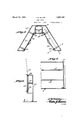
- Figure 1 is a vertical sectional view through the stove, the section being taken at approximately the center of the stove.
- Figure 2 is a top plan view.
- Figure 3 is a section on line 33 of Fig- W ure 1..
- Figure 4 is a View looking toward the inner face of the water tank
- Figure 5 is a section on line 55 of Figure 3.
- Figure 6 is a section on line 66 of Figure 5.
- Figure 7 is a section on line 7-'7 of F igure 5.
- Figure 8 is a sectional View through a modified form of warming chamber.
- Figure 9 is a detail view of part of Figure 8.
- the stove A is formed with a rear extension 1' at its upper 3 part which is of substantially V "shape in plan and the smoke pipe 2 is in communication with the rear portion of this extension, said smoke pipe extending upwardlyv from the top of the extension.
- the oven 3 extends from one side of the stove to the other, with its rear wall spaced from the rear wall of the stove and its bottom spaced from the bottom of the stove, The oven extends to the front of the stove, except at the central portion of the oven, i which has a recess eat the center thereof, said recess terminating short of the bottom of the oven so thatgthe lower central part of the oven als-o extends, to the front of the stove, as shown at 3" in Figure 1.
- the top of the oven is spaced from the top of the stove so that the products of combustion can passfrom the firebox across the top of the oven into the rear extension 1 and'then pass through the pipe'2.. Of course, some of theheat will contact the rear and bottom walls of the oven so thatthe oven is intensely heated by portions of its front part enclosing the fire box and the products of combustion passing over thetopof the overland the heat contacting the bottom and rearwalls of the oven. Access is had to the oven through the door 7 915 arranged at one side oft'he oven.
- Fuel can be placed in the fire box through an opening in the front upper part of the stove which is closed by a door 8 having adamper 9 there- I in and a doorl-O provides access to the lower part of the fire box.
- a detachable shelf "11 is placed under the door 10 and detachable shelves 12 are placed on the side of the stove,
- a tank 13 is detach-ably connected to the side of the stove opposite the door 7 and a door 14 in the front of the stove provides access to the space under the oven so that said space can be cleaned.
- a substantially V shaped warming compartment 15 is seated on the extension 1 of the stove and the pipe 2 passes through the rear part of this compartment.
- Sliding doors 16 are placed in the front of the compartment so that access can be gained to the side and middle portions of the compartment by opening these doors.
- Removable shelves 17 are placed in the compartment to support articles placed in the compartment. and the bottom 18 of the lower chamber, formed by the sides and central portion of the compartment, is spaced from the top of the stove so that articles can be placed on the stove under the compartment.
- the damper 19 for the 5 pipe 2 is manipulated through the space under the central chamber.
- the top of the plate is provided with the usual lids 20, some of which are in the extension 1 and those in the extension are carried by a removable plate 21.
- the usual removable bridge piece 22 is placed between the lids and the front part of the stove.
- Each door 16 operates in vertical guide-' ways 23 formed in the compartment and 15 notches 2 1 are formed in the walls at the upper ends of the guideways so that the door can be tilted when in its fully open position to cause its lower end to rest in the notches, as shown in dotted lines in Figure 6, to hold the door in open position.
- FIGS 8 and 9 show a modification of the warming chamber in which each door 16' thereof is moved upwardly and inwardly into the compartment instead of being moved ver- 25 tically.
- the edges of the door operate in the guideways 16 in the compartment, at the top thereof. 7
- a stove of the class described having an extension at the upper part of its rear p0rtion, a substantially V shaped Warming chamher seated on the extension, a smoke pipe for the stove which passes through the central part of the warming chamber, an oven in the stove, a fire box in the stove, said oven having a recess at the central portion of its front part in which the fire box is placed and said oven being spaced from the top and bottom of the stove and from the rear thereof and a door for the oven arranged at one side of the stove.
Landscapes
- Engineering & Computer Science (AREA)
- Chemical & Material Sciences (AREA)
- Combustion & Propulsion (AREA)
- Mechanical Engineering (AREA)
- General Engineering & Computer Science (AREA)
- Solid-Fuel Combustion (AREA)
Description
J. M. WATTS COAL STOVE March 22, 1 932.
Filed Aug. 4, 1950 5 Sheets-Sheet (1M ffajmmma I my! ATTORNEY March 22,* 1932. WATTS 1,850,161
GOAL STOVE Filed Aug. 4, 1930 5 Sheets-Sheet 2 III ATTORNEY Patented Mar. 22, 1932.
JOHN M. warms, or KANSAS orrY; KANSAS I I COAL STOVE,
Application filed August 4, 1930. Serial No. 472,,779.
This invention relates to a cook stove, the general object of the invention being to provide a stove which can be made of small size and which has a small fire box so that the 5 consumption of fuel is small and to provide the stove with a warming chamber which is of substantially V shape and through a part of which the smoke pipe passes so that the chamber is warmed by the products of combustion passing through'the smoke pipe as well as by the heat from the stove.
This invention also. consists in certain other features of construction and in the combination and arrangement of the several parts, to be hereinafter fully described, illustrated in the accompanying drawings and specifically pointed out in the appended claim.
In describing the invention in detail, reforence will be had to the accompanying drawings wherein like characters denote like or corresponding parts throughout the several views, and in which Figure 1 is a vertical sectional view through the stove, the section being taken at approximately the center of the stove. Figure 2 is a top plan view.
Figure 3 is a section on line 33 of Fig- W ure 1..
Figure 4 is a View looking toward the inner face of the water tank Figure 5 is a section on line 55 of Figure 3.
Figure 6 is a section on line 66 of Figure 5.
Figure 7 is a section on line 7-'7 of F igure 5. r
Figure 8 is a sectional View through a modified form of warming chamber.
Figure 9 is a detail view of part of Figure 8.
As shown in these drawings, the stove A is formed with a rear extension 1' at its upper 3 part which is of substantially V "shape in plan and the smoke pipe 2 is in communication with the rear portion of this extension, said smoke pipe extending upwardlyv from the top of the extension. The oven 3 extends from one side of the stove to the other, with its rear wall spaced from the rear wall of the stove and its bottom spaced from the bottom of the stove, The oven extends to the front of the stove, except at the central portion of the oven, i which has a recess eat the center thereof, said recess terminating short of the bottom of the oven so thatgthe lower central part of the oven als-o extends, to the front of the stove, as shown at 3" in Figure 1. t The M space 4 formed between the upper part of the oven and the front of thestove receives the fire box 5 and the lower part of saidspace forms the ash pit '6. "The top of the oven is spaced from the top of the stove so that the products of combustion can passfrom the firebox across the top of the oven into the rear extension 1 and'then pass through the pipe'2.. Of course, some of theheat will contact the rear and bottom walls of the oven so thatthe oven is intensely heated by portions of its front part enclosing the fire box and the products of combustion passing over thetopof the overland the heat contacting the bottom and rearwalls of the oven. Access is had to the oven through the door 7 915 arranged at one side oft'he oven. Fuel can be placed in the fire box through an opening in the front upper part of the stove which is closed by a door 8 having adamper 9 there- I in and a doorl-O provides access to the lower part of the fire box. A detachable shelf "11 is placed under the door 10 and detachable shelves 12 are placed on the side of the stove,
one above and one below the door 7 A tank 13 is detach-ably connected to the side of the stove opposite the door 7 and a door 14 in the front of the stove provides access to the space under the oven so that said space can be cleaned. t
A substantially V shaped warming compartment 15 is seated on the extension 1 of the stove and the pipe 2 passes through the rear part of this compartment. Sliding doors 16 are placed in the front of the compartment so that access can be gained to the side and middle portions of the compartment by opening these doors. Removable shelves 17 are placed in the compartment to support articles placed in the compartment. and the bottom 18 of the lower chamber, formed by the sides and central portion of the compartment, is spaced from the top of the stove so that articles can be placed on the stove under the compartment. The damper 19 for the 5 pipe 2 is manipulated through the space under the central chamber. The top of the plate is provided with the usual lids 20, some of which are in the extension 1 and those in the extension are carried by a removable plate 21. The usual removable bridge piece 22 is placed between the lids and the front part of the stove.
Each door 16 operates in vertical guide-' ways 23 formed in the compartment and 15 notches 2 1 are formed in the walls at the upper ends of the guideways so that the door can be tilted when in its fully open position to cause its lower end to rest in the notches, as shown in dotted lines in Figure 6, to hold the door in open position.
Figures 8 and 9 show a modification of the warming chamber in which each door 16' thereof is moved upwardly and inwardly into the compartment instead of being moved ver- 25 tically. The edges of the door operate in the guideways 16 in the compartment, at the top thereof. 7
It is thought from the foregoing description that the advantages and novel features of the invention will be readily apparent.
It is to be understood that changes may be made in the construction and in the combination and arrangement of the several parts, provided that such changes fall within the scope of the appended claim.
What I claim is:
A stove of the class described having an extension at the upper part of its rear p0rtion,a substantially V shaped Warming chamher seated on the extension, a smoke pipe for the stove which passes through the central part of the warming chamber, an oven in the stove, a fire box in the stove, said oven having a recess at the central portion of its front part in which the fire box is placed and said oven being spaced from the top and bottom of the stove and from the rear thereof and a door for the oven arranged at one side of the stove.
In testimony whereof I affix my signature.
JOHN M. WATTS.
Priority Applications (1)
| Application Number | Priority Date | Filing Date | Title |
|---|---|---|---|
| US472779A US1850161A (en) | 1930-08-04 | 1930-08-04 | Coal stove |
Applications Claiming Priority (1)
| Application Number | Priority Date | Filing Date | Title |
|---|---|---|---|
| US472779A US1850161A (en) | 1930-08-04 | 1930-08-04 | Coal stove |
Publications (1)
| Publication Number | Publication Date |
|---|---|
| US1850161A true US1850161A (en) | 1932-03-22 |
Family
ID=23876910
Family Applications (1)
| Application Number | Title | Priority Date | Filing Date |
|---|---|---|---|
| US472779A Expired - Lifetime US1850161A (en) | 1930-08-04 | 1930-08-04 | Coal stove |
Country Status (1)
| Country | Link |
|---|---|
| US (1) | US1850161A (en) |
-
1930
- 1930-08-04 US US472779A patent/US1850161A/en not_active Expired - Lifetime
Similar Documents
| Publication | Publication Date | Title |
|---|---|---|
| US2222065A (en) | Combination combustion and electric stove | |
| US1850161A (en) | Coal stove | |
| US1531405A (en) | Stove | |
| US2224316A (en) | Kitchen stove | |
| US903834A (en) | Oven. | |
| US2007297A (en) | Stove construction | |
| US1494843A (en) | Oil-burning range | |
| US1550638A (en) | Army field kitchen | |
| US1416478A (en) | Range | |
| US31930A (en) | Hosea h | |
| US2220637A (en) | Air heater for ranges | |
| US1931959A (en) | Stove or furnace construction | |
| US2295889A (en) | Cooking range or stove | |
| US32829A (en) | Cooking-stove | |
| US1496267A (en) | Cookstove | |
| US76315A (en) | evard | |
| US1994423A (en) | Cooking range | |
| US1521832A (en) | Combined kitchen cabinet and range | |
| US1371191A (en) | Cooking-stove | |
| US1143504A (en) | Combined heating and cooking stove. | |
| US2161196A (en) | Cooking stove | |
| US22120A (en) | Joshua -harrison | |
| US1582532A (en) | Cooking oven | |
| US706589A (en) | Stove. | |
| US1394508A (en) | Stove |