US1850157A - Liner setter head - Google Patents
Liner setter head Download PDFInfo
- Publication number
- US1850157A US1850157A US431143A US43114330A US1850157A US 1850157 A US1850157 A US 1850157A US 431143 A US431143 A US 431143A US 43114330 A US43114330 A US 43114330A US 1850157 A US1850157 A US 1850157A
- Authority
- US
- United States
- Prior art keywords
- section
- well
- casing
- collar
- pipe section
- Prior art date
- Legal status (The legal status is an assumption and is not a legal conclusion. Google has not performed a legal analysis and makes no representation as to the accuracy of the status listed.)
- Expired - Lifetime
Links
- 210000002832 shoulder Anatomy 0.000 description 5
- 230000000875 corresponding effect Effects 0.000 description 2
- 230000008878 coupling Effects 0.000 description 2
- 238000010168 coupling process Methods 0.000 description 2
- 238000005859 coupling reaction Methods 0.000 description 2
- 238000005553 drilling Methods 0.000 description 2
- 239000004568 cement Substances 0.000 description 1
- 238000010276 construction Methods 0.000 description 1
- 230000008014 freezing Effects 0.000 description 1
- 238000007710 freezing Methods 0.000 description 1
- 239000000463 material Substances 0.000 description 1
- 230000002093 peripheral effect Effects 0.000 description 1
Images

Classifications
-
- E—FIXED CONSTRUCTIONS
- E21—EARTH OR ROCK DRILLING; MINING
- E21B—EARTH OR ROCK DRILLING; OBTAINING OIL, GAS, WATER, SOLUBLE OR MELTABLE MATERIALS OR A SLURRY OF MINERALS FROM WELLS
- E21B19/00—Handling rods, casings, tubes or the like outside the borehole, e.g. in the derrick; Apparatus for feeding the rods or cables
-
- Y—GENERAL TAGGING OF NEW TECHNOLOGICAL DEVELOPMENTS; GENERAL TAGGING OF CROSS-SECTIONAL TECHNOLOGIES SPANNING OVER SEVERAL SECTIONS OF THE IPC; TECHNICAL SUBJECTS COVERED BY FORMER USPC CROSS-REFERENCE ART COLLECTIONS [XRACs] AND DIGESTS
- Y10—TECHNICAL SUBJECTS COVERED BY FORMER USPC
- Y10S—TECHNICAL SUBJECTS COVERED BY FORMER USPC CROSS-REFERENCE ART COLLECTIONS [XRACs] AND DIGESTS
- Y10S285/00—Pipe joints or couplings
- Y10S285/92—Remotely controlled
Definitions
- the object of this invention is to provide means for lowering a section of well casing orliner into the well to increase the length of the casing as may be required by an in crease in depth of the well.
- the well casing is usually cemented in the hole or bore of the well, and during drilling operation the depth of the bore'is often increased beyond the lower end of the well casing with the result that it is necessary to insert an additional section of well casing tocompensate for the increased depth ofthe well and as before intimated it is therefore a primary object of this invention to provide means'to facilitate adding the required casing section to the lower end of the well casing and subsequentlycementing" the additional section in position in the bottom of the well.
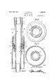
- Figure 1 is an elevational view of the device for setting the additional sectionof well casing.
- Figure 2 is a transverse sectional view taken substantially on the line 2-2 of Fig- ,BOl ure 3
- Figure 3 is a vertical longitudinal sectional view taken through the structure shown in Figure 1.
- Figure 4 is a transverse sectional view taken substantially on the line 4 4of Figure 3.
- Figure 5 is a similar View takensubstantially on the line 5'5 of Figure 3.
- Figure 6 is a perspective view of a key member forming part of the invention.
- my device for setting an additional section of casing in the bottom -of the well for increasing the length of the original well casing consists in the provision of an open ended cylindrical casing collar 5 provided intermediate its ends with internal threads 5a to facilitate coupling of the col- 0. lar 5 on the upperend of the casing section to be lowered into the "well.
- the threads 5a are right hand threads.
- the threads 5a are located below an'annular internal flange 7 adapted to provide a seat for a bearing vstructure which include's 58',
- a tube or pipe section 8 extends through the col1ar:5, and intermediate its ends the tube '8 is provided with an annular external shoul der 12 adapted to rest on the upper bearing race 9,- the lower end of the tube 8 preferably terminating substantially flush with the cor responding end of the collar 5.
- the shoulder 12 cooperates with a nut 14 threadedly engaged with'the tube 8 as at 13 for rotatably retaining on the tube or vpipe section 8 the bearing structure including the parts 9, 10
- an externally threaded bushing 15 provided'with akeyway 16 cooperating with a'keyway 17 provided on the periphery of the pipe 'sectionor tube 8for accommodating a key 18 to lockthe bushingl5 on the tube or pipe section 8 against rotation relative to said tubeor pipe section.
- V V y In actual operation-nut 14 vis first screwed on the-section 8 subsequent to the positioning of the bearing structure on the pipe'or tube 8, nut 14 thus servingas before mentioned, in conjunction with shoulder 12 for rotatably supporting the bearing structure on the pipe section 8.
- bushing "15- is then placed on the tube or'pipe section 81and keyed thereto in the manner before explained, and the tube '8 is then inserted through the collar 5'and by rotating the tube, it 1 will be apparent that bushing 15 will be screwed intoengag'ement with the upper internallyjthreaded portion 6 of the collar 5 with; thebearing structure arrangedbetween.
- Pipe section 8 is also provided at its upper end with external threads for cooperation with internal threads provided on the lower end of a conventional well drilling tool string, a portion of which is designated by the reference character P.
- the section of casing to be lowered into the well (said section not being shown) is as before mentioned at its upper end threadedly engaged with the threaded portion 5a of the collar 5 so that as is apparent, the lower section a of the tubing will extend through this casing section (not shown) and will, as is conventional, project at its lower end beyond the corresponding end of such casing section.
- the string of tubing including the sections a, a, and the pipe section 8 can then be removed by rotating the tool string P in the manner well known in. the art thus unscrewing the nut 15 from the collar 5 so that the tubing string referred to may be drawn upwardly leaving the collar 5 and the casing section secured thereto cemented in the bottom of the well.
- the bearing structure together with the nut 14 will also be removed upon the removal of said tubing string.
- casing collar comprising a substantially cylindrical open ended body provided with internal oppositely threaded portions, a pipe section extending through said collar, means for preventing said pipe section from passing entirely through the collar in one direction, said collar having one threaded portion thereof adapted to be engaged with a correspond ingly threaded portion of a casing section, an externally threaded bushing keyed to said pipe section and engaged with the other threaded portion of said collar to thereby releasably retain said pipe section in operative position with respect to said collar.
- Means for setting and cementing well casing sections comprising an open end ed cylindrical collar provided with an internal annular seat, tubing for jconducting a cementitious material through the collar and casing section connected therewith and in cluding a pipe section concentric of the collar, a bearing rotatable on the pipe section and adapted to engage said seat, means for rotatably retaining the bearing on said pipe section, an externally threaded bushing disposed about said pipe section and having threaded connection with said collar, and means for keying said bushing to said pipe section.
- a device for setting well casings comprising in combination a collar provided with means for coupling to the casing to be set, an internal annular shoulder formed on the peripheral wall of said collar, a bearing structure adapted to rest on said shoulder and adapted to have suspended therethrough a section of well tubing, an externally threaded bushing screwed within the collar above said bearing structure, and means for keying the bushing to said section of well tubing.
Landscapes
- Engineering & Computer Science (AREA)
- Life Sciences & Earth Sciences (AREA)
- Geology (AREA)
- Mining & Mineral Resources (AREA)
- Mechanical Engineering (AREA)
- Physics & Mathematics (AREA)
- Environmental & Geological Engineering (AREA)
- Fluid Mechanics (AREA)
- General Life Sciences & Earth Sciences (AREA)
- Geochemistry & Mineralogy (AREA)
- Earth Drilling (AREA)
Description
2 Sheets-Sheet 1 Filed Feb 25, 1930 Inventor A iiorney LINER SETTER HEAD Filed Feb. 25, 1930 2 Sheets-Sheet 2 i/ gfaiziz Wflzifez; 20
A tiorney ,4; v W By T Patented Mar. 22, 1932 PATENT OFFICE.
3.01m w. BITTER, or DUNCAN, OKLAHOMA LINER BETTER HEAD Application filed February 25, 1930. Serial No. 431,143. 8
' The object of this invention is to provide means for lowering a section of well casing orliner into the well to increase the length of the casing as may be required by an in crease in depth of the well.
7 As is well known in the art, the well casingis usually cemented in the hole or bore of the well, and during drilling operation the depth of the bore'is often increased beyond the lower end of the well casing with the result that it is necessary to insert an additional section of well casing tocompensate for the increased depth ofthe well and as before intimated it is therefore a primary object of this invention to provide means'to facilitate adding the required casing section to the lower end of the well casing and subsequentlycementing" the additional section in position in the bottom of the well.
The nature of the invention, as well as its many objects and advantages will be apparent' from a study of the following description taken in connection with the accompanying drawings wherein Figure 1 is an elevational view of the device for setting the additional sectionof well casing.
Figure 2 ,is a transverse sectional view taken substantially on the line 2-2 of Fig- ,BOl ure 3 V Figure 3 is a vertical longitudinal sectional view taken through the structure shown in Figure 1. V
Figure 4 is a transverse sectional view taken substantially on the line 4 4of Figure 3.
Figure 5 is a similar View takensubstantially on the line 5'5 of Figure 3.
Figure 6 is a perspective view of a key member forming part of the invention.
lVith reference more in detail to the drawings, it will be seen that my device for setting an additional section of casing in the bottom -of the well for increasing the length of the original well casing, consists in the provision of an open ended cylindrical casing collar 5 provided intermediate its ends with internal threads 5a to facilitate coupling of the col- 0. lar 5 on the upperend of the casing section to be lowered into the "well. Preferably the threads 5a are right hand threads.
The threads 5a are located below an'annular internal flange 7 adapted to provide a seat for a bearing vstructure which include's 58',
upper and lower bearing races 9 and/l0 and ball bearings 11 interposed between said races. v
A tube or pipe section 8 extends through the col1ar:5, and intermediate its ends the tube '8 is provided with an annular external shoul der 12 adapted to rest on the upper bearing race 9,- the lower end of the tube 8 preferably terminating substantially flush with the cor responding end of the collar 5. The shoulder 12 cooperates with a nut 14 threadedly engaged with'the tube 8 as at 13 for rotatably retaining on the tube or vpipe section 8 the bearing structure including the parts 9, 10
and 11.
Disposed about the tube or pipe section 8 above said bearing structure is an externally threaded bushing 15 provided'with akeyway 16 cooperating with a'keyway 17 provided on the periphery of the pipe 'sectionor tube 8for accommodating a key 18 to lockthe bushingl5 on the tube or pipe section 8 against rotation relative to said tubeor pipe section. V V y In actual operation-nut 14 vis first screwed on the-section 8 subsequent to the positioning of the bearing structure on the pipe'or tube 8, nut 14 thus servingas before mentioned, in conjunction with shoulder 12 for rotatably supporting the bearing structure on the pipe section 8. The bushing "15- is then placed on the tube or'pipe section 81and keyed thereto in the manner before explained, and the tube '8 is then inserted through the collar 5'and by rotating the tube, it 1 will be apparent that bushing 15 will be screwed intoengag'ement with the upper internallyjthreaded portion 6 of the collar 5 with; thebearing structure arrangedbetween. the bushing 15 and-theseat The pipe section Sisadapted to be arranged between two sections a, a: of a'conventionfal typeof tubing, the pipev section 8(at its-upper end being provided with internal threads for cooperationw-ith the external threads on one 1 end of the tubing section a as at 19, and at its lower end the pipe section 8 is provided with internal threads for cooperation with the external threads on the upper end of the section a of the tubing as at 20.
Pipe section 8 is also provided at its upper end with external threads for cooperation with internal threads provided on the lower end of a conventional well drilling tool string, a portion of which is designated by the reference character P.
The section of casing to be lowered into the well, (said section not being shown) is as before mentioned at its upper end threadedly engaged with the threaded portion 5a of the collar 5 so that as is apparent, the lower section a of the tubing will extend through this casing section (not shown) and will, as is conventional, project at its lower end beyond the corresponding end of such casing section.
All the parts being assembled as above i11- dicated, the assembly is then lowered into the Well passing through the original casing in the well for positioning said casing section (not shown) at the bottom of the well to form an extension of the original well casing. Cement is then, in the usual manner pumped through the tubing now including the section a, pipe 8 and section a, the ce ment passing outwardly through the lower end of the section a to be forced upwardly about the said casing section connected with the collar 5 for cementing or freezing said casing section in proper position at the bottom of the well to form a continuation of the original casing.
When this operation has been completed, the string of tubing including the sections a, a, and the pipe section 8 can then be removed by rotating the tool string P in the manner well known in. the art thus unscrewing the nut 15 from the collar 5 so that the tubing string referred to may be drawn upwardly leaving the collar 5 and the casing section secured thereto cemented in the bottom of the well. Of course, and as is thought apparent, the bearing structure together with the nut 14 will also be removed upon the removal of said tubing string.
It is thought that from the foregoing description, taken in connection with the accompanying drawings, a clear understanding, of the operation and construction is shown in the advantages of a device of this character and will be had by those skilled in the art without a more detailed description.
Even though I have herein shown and described thepreferred form of my invention, it is to be understood that the same is susceptible of changes fully comprehended by the spirit of the invention as herein described, within the scope of the appended claims.
Having thus described my invention, what I claimas new is 1. In a device of the character described, a
casing collar comprising a substantially cylindrical open ended body provided with internal oppositely threaded portions, a pipe section extending through said collar, means for preventing said pipe section from passing entirely through the collar in one direction, said collar having one threaded portion thereof adapted to be engaged with a correspond ingly threaded portion of a casing section, an externally threaded bushing keyed to said pipe section and engaged with the other threaded portion of said collar to thereby releasably retain said pipe section in operative position with respect to said collar.
2. Means for setting and cementing well casing sections, and comprising an open end ed cylindrical collar provided with an internal annular seat, tubing for jconducting a cementitious material through the collar and casing section connected therewith and in cluding a pipe section concentric of the collar, a bearing rotatable on the pipe section and adapted to engage said seat, means for rotatably retaining the bearing on said pipe section, an externally threaded bushing disposed about said pipe section and having threaded connection with said collar, and means for keying said bushing to said pipe section.
3. A device for setting well casings comprising in combination a collar provided with means for coupling to the casing to be set, an internal annular shoulder formed on the peripheral wall of said collar, a bearing structure adapted to rest on said shoulder and adapted to have suspended therethrough a section of well tubing, an externally threaded bushing screwed within the collar above said bearing structure, and means for keying the bushing to said section of well tubing.
In testimony whereof I affix my signature.
JOHN W. BITTER.
Priority Applications (1)
| Application Number | Priority Date | Filing Date | Title |
|---|---|---|---|
| US431143A US1850157A (en) | 1930-02-25 | 1930-02-25 | Liner setter head |
Applications Claiming Priority (1)
| Application Number | Priority Date | Filing Date | Title |
|---|---|---|---|
| US431143A US1850157A (en) | 1930-02-25 | 1930-02-25 | Liner setter head |
Publications (1)
| Publication Number | Publication Date |
|---|---|
| US1850157A true US1850157A (en) | 1932-03-22 |
Family
ID=23710661
Family Applications (1)
| Application Number | Title | Priority Date | Filing Date |
|---|---|---|---|
| US431143A Expired - Lifetime US1850157A (en) | 1930-02-25 | 1930-02-25 | Liner setter head |
Country Status (1)
| Country | Link |
|---|---|
| US (1) | US1850157A (en) |
-
1930
- 1930-02-25 US US431143A patent/US1850157A/en not_active Expired - Lifetime
Similar Documents
| Publication | Publication Date | Title |
|---|---|---|
| US3006415A (en) | Cementing apparatus | |
| US2150228A (en) | Packer | |
| US1560763A (en) | Packing head and blow-out preventer for rotary-type well-drilling apparatus | |
| US2624549A (en) | Method and means of rotary drilling | |
| US2316402A (en) | Cementing wells | |
| US1636032A (en) | Milling tool | |
| US2553874A (en) | Directional drilling apparatus | |
| US3136367A (en) | Liner releasing tool | |
| US2139983A (en) | Back pressure plug valve | |
| US2913052A (en) | Liner set tool | |
| US1850157A (en) | Liner setter head | |
| US2142859A (en) | Well-bore deflecting tool | |
| US2859826A (en) | Cementing collar for drilling with casing | |
| US2551995A (en) | Rotary core drill with jar mechanism | |
| US2249732A (en) | Off center reamer | |
| US3033290A (en) | Screw-set non-retrievable packer | |
| US2092048A (en) | Packer setting device | |
| US2097755A (en) | Liner setting tool | |
| US1079836A (en) | Apparatus for boring wells. | |
| US2101640A (en) | Method and apparatus for cementing wells | |
| US1651537A (en) | Controlling apparatus for oil wells | |
| US1750143A (en) | Cementing head | |
| US2929452A (en) | Well pipe wash-over and clean-out tool | |
| US2218496A (en) | Take-off tool for wells | |
| US2075293A (en) | Well casing attachment |