US185011A - Improvement in water-motors - Google Patents
Improvement in water-motors Download PDFInfo
- Publication number
- US185011A US185011A US185011DA US185011A US 185011 A US185011 A US 185011A US 185011D A US185011D A US 185011DA US 185011 A US185011 A US 185011A
- Authority
- US
- United States
- Prior art keywords
- water
- piston
- chambers
- crank
- shaft
- Prior art date
- Legal status (The legal status is an assumption and is not a legal conclusion. Google has not performed a legal analysis and makes no representation as to the accuracy of the status listed.)
- Expired - Lifetime
Links
- XLYOFNOQVPJJNP-UHFFFAOYSA-N water Substances O XLYOFNOQVPJJNP-UHFFFAOYSA-N 0.000 description 21
- 238000012856 packing Methods 0.000 description 9
- 230000006698 induction Effects 0.000 description 5
- 238000005192 partition Methods 0.000 description 5
- 238000005266 casting Methods 0.000 description 4
- 238000010276 construction Methods 0.000 description 3
- 210000004907 gland Anatomy 0.000 description 2
- 229910001018 Cast iron Inorganic materials 0.000 description 1
- 235000013382 Morus laevigata Nutrition 0.000 description 1
- 244000278455 Morus laevigata Species 0.000 description 1
- 210000005069 ears Anatomy 0.000 description 1
- 238000003780 insertion Methods 0.000 description 1
- 230000037431 insertion Effects 0.000 description 1
- 239000000314 lubricant Substances 0.000 description 1
- 238000004519 manufacturing process Methods 0.000 description 1
- 239000002184 metal Substances 0.000 description 1
- 239000004576 sand Substances 0.000 description 1
- 239000007787 solid Substances 0.000 description 1
- 230000002459 sustained effect Effects 0.000 description 1
Images


Classifications
-
- F—MECHANICAL ENGINEERING; LIGHTING; HEATING; WEAPONS; BLASTING
- F04—POSITIVE - DISPLACEMENT MACHINES FOR LIQUIDS; PUMPS FOR LIQUIDS OR ELASTIC FLUIDS
- F04B—POSITIVE-DISPLACEMENT MACHINES FOR LIQUIDS; PUMPS
- F04B1/00—Multi-cylinder machines or pumps characterised by number or arrangement of cylinders
Definitions
- My said improvements relate to piston-motors, and to such as embody two cylinders and pistons,which are coupled together by a crankshaft, and slide-valves, which are actuated by eccentrics.
- Such motors are well adapted for light service, and, to meet a general demand, they should be as inexpensive as possible, capable of yielding a maximum of power to the quantity of water employed, durablein all their parts, and so simple in their construction as to ⁇ be easily repaired, if necessary.
- One feature of my invention consists in a novel shell or casing, which incloses all the moving parts of my motor.
- Said shell is composed of five separate sections, which, when placed in position endwise, are secured together by longitudinal bolts.
- the main sections, containing the induction and eduction water-passages, the valve chambers or seats, and the piston-cylinders, are two counterparts, cast from one pattern and united by nuts, as described and claimed in my aforesaid application for patent.
- the rear-end section or head of the shell contains two separate cylindrical chambers for the reception of guidingrods for the pistons.
- the front head is composed of two sections, each of which contains a part of three chambers. All the joints between the sections are transverse to the line of the piston-cylinders.
- each of' the piston-cylinders communicates with one of the chambers in the rear head, and also with one of the chambersl of the front head, the three constituting, in fact, one chamber,which packing is required about the mechanism which connects the pistons and cranks, and also whereby the water contained in the crankchambers is guarded against disturbance by the water passing into and from the cylinders with which said chambers communicate.
- Another feature of my invention consists in the combination, with a piston-cylinder, of a piston and crank, connected by a pitman, a guiding-rod on the opposite side of the piston, and a guide-rod bearing, whereby the piston is made to operate as a cross-head for its pitman and crank.
- the guiding-rod of the piston has its bearing extended beyond the rear end of the cylinder; and another feature of my invention consists in the combination, with a piston arranged to operate asa cross-head, and having a guiding-rod and a guide-rod bearing, of a chamber communicating with, but extendedv beyond, the cylinder and the guide-rod bearing, for the reception of the guidingrod,where by, although the bearing and the guiding-rod are sufficiently well tted to each other to secure good operative service, no water-tight packing around said rod is requisite.
- each crank occupies a separate chamber, be built up in lengths, in amanner well known.
- lhe eccentrics also occupya separate chamber located between the crank-chambers, and are mounted upon a short length of the crankshaft, and therefore the two eccentrics are placed in the chamber with their holes coincident, and the section of shaft is inserted from one of the crank-chambers through the dividing-wall.
- Economy in space being desirable,
- a', Fig. 3, and the ...transverse sectional a novel means-for securing the eccentrics on the shaft; and one feature ofimy invention consist-s in the combination, with the eccentrics, of a secton of shaft which is tubular and threaded internally throughout its length, two screws with pointed ends within the shaft, and two radial studs in the shaft, each beneath the seat oi' an eccentric, (whereby, on turning both studs lnay be advanced and made to engage with the eccentrics, and thereby secure them on the shaft and admit of their ready adjustment.
- FIG. 1 Sheet 1 represents one of my motors in perspective.
- Figs. 2 and 3 represent the same, respectively, in longitudinal and transverse vertical section.
- Fig. '2 contains sectional views both on ⁇ lines w a.' and y latter igure ⁇ contains a view on line w Fig. 2.
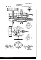
- Fig. 4 Sheet 2, represents the saine in longi. tudinal horizontal section on a liiiewith the crank-shaft.
- Fig. 5 represents the same in end View, with the front head of the shell detached, as indicated at linee, Fig. 2.
- Fig. 1 represents one of my motors in perspective.
- Figs. 2 and 3 represent the same, respectively, in longitudinal and transverse vertical section.
- Fig. '2 contains sectional views both on ⁇ lines w a.' and y latter igure ⁇ contains a view on line w Fig. 2.
- Fig. 4 represents the saine in long
- Fig. 6 represents, in longitudinal section, the portion of the crank-shaft whichcarries the valve- 'operating eccentrics, and Yexhibits the means whereby they are secured on the shaft.
- Fig. 7 represents the rear head of the motor in end view, and reduced in size.
- Fig. 8 represents, in end view, the inside section ot' the front head ofthe shell.
- Fig. 9 represents, in end view, one of the parts of the shell at its point of junction with its counterpart.
- the shell .of the motor is constructed in five sections, and, as before stated, the main body thereof is constructed in accordance with an invention described and .claimed by me in another application for Letters Patent.
- the rear head a2 is of peculiar construction, and contains two separate chambers, each of which is opposite the rear end of a pistoncylinder, and extends to the rear thereof a distance equal to the length of stroke made by the piston.
- Section a3 is square in transverse section, and divided by vertical partitions in three separatechambers, which are open at each end of nthe ⁇ section.
- the two outside chambers communicate with the piston-cylinders, and contain ⁇ the cranks. These crank-chambers are separated from the cylinders, ⁇ as shown, by a partition, which Vis slotted for the pitmen.
- the intermediate ⁇ chamber contains the eccentrics ⁇ and commu nicates with the valve-chambers.
- This section ai is united to the main body of the shell by four long bolts, d. Their heads engage against an in terior iiange ofthe section a3, and they extend rearward through the center ofthe water-passages A and B, and through holes in the flange of the rear head-section a2, at which point their nuts are applied, thus firmly uniting these four sections.
- This sectionl a3 is also provided at each front corner with a lateral bolt-ear.
- the front headsec tion a4 is box-like in form, with two vertical partitions coincident with those in section a3, which divide it into three chambers, so that when the head is in position they communicate with and constitute extension of the two cranlrchambers and the eccentric chamber.
- ⁇ Sections a and a4 are united by the bolts d at each corner.
- any suitable packing may be employed.
- gum packing cut in a form ⁇ to correspond with the coincident metallic surfaces is desirable.
- the joint between sections a and al is essential for cheap and convenient casting and finishing, and that between al and a2, and also between a and' a3, are both essential, because of the radical dii'erence in the form of the sections (to be considered in connectionwith casting) ⁇ and the necessity of access to the internal portions of' the main body of the shell.
- the joint between a3 and a* is essential for the location, insertion, and adjustment of the crank-shaft.
- the motor is mounted upon a suitable standard or block, as shown, wherei by it may be secured to a lproper foundation.
- the pistons C and C are so constructed that they serve as their own cross-heads. They have an extensive longitudinal bearing with their cylinders, and are directly connected to their pitmen e b v means of ears on the front of the piston-head, and a transverse pin, e', which is entered through a hole in the barrel of the piston.
- Each has a guiding-rod, as at f, projecting ⁇ from the opposite side of the head.
- This rod has a good longitudinal bearing or seat in thecylindrical hub g, which is sustained by arms and a ring secured in position at the rear end of the cylinder by being confined between the shoulder ot' an annular recess in the cylinder and the inner face of the rear head.
- Each of the piston-cylinders therefore, cornmunicates with one lof the guidingrod chainbers, and also with one of the crank-chambers, the three, as a' whole, constitutingvone chamber, whichis divided into two chambers by the head of the piston. For this reason all of the moving parts contained therein are surrounded by water, and no packing is required around the crank-connections with the piston, or around its guiding-rod.
- D and D denote the two slide-valves. They are tubular in form, and have a head or piston at each end, as at t', which alternately pass the ports t" at each end of the piston-cylinders.
- the annular Vspace between the heads of the valve when in its chamber constitutes a water-waywhich may be employed for eduction or induction; but this space at each valve is described herein as an eduction-passage.
- These valves are connected with the crankshaft E by means of the eccentrics ll and.
- eccentric rods 70k' and arranged with relation to the piston-cranks much the sameI as slide-valves are in double-cylinder steamengines, with the exception that there is, of course, no lap or lead with these valves, because of the radical difference between water under pressure and steam.
- the eccentric rods are connected with the valves by means of a transverse pin, which is'located at one end of the valve, and does not materially obstruct the water-way.
- the valves being tubular, but little power is requisite for their operation.
- the live water is supplied to each end of the valve-chambers from the water-passages A by means of the recesses m in each head of the shell.
- Each recess m in the rear head connects directly an induction-passage, A, with the' adjacent valve-chamber; but the recesses in the front head connect both with the central chamber, which contains the eccentrics, and with the valve-chambers 5 in other words, the eccentric chamber contains live water, from which both valves are supplied, the live water in both valves entering the ports t" to the pistoncylinders over the ends of the valves.
- the exhaust water leaves the piston-cylinders by the same ports i', but enters the valve-chambers between the heads of thevalves, and
- the crank-shaft E is preferably built up of short lengths, united by complex cranks in a manner well known. This mode of construction enables me to provide solid bearings in the walls and partit-ions of the front head.
- the two outer ends of the crank-shaft are provided with long bearings cast with the headyand with glands or stuffing-boxes, which constitute the Aonly packing required in my motor, except that which is requisite for-securing tight joints between the sections composing the shell.
- the piston being long and operated by water, requires no special packing, although annular recesses therein may be prolitably employed, in a manner well known.
- the sectiono of the main shaft is shown in Fig. 6. It is tubular, threaded internally throughout its length, and contains two screws, p, entered from opposite ends of the section. These screws have pointed tips, which engage their tapering surfaces against the inner ends of radial pins q in the shaft, and force these latter outward into holes therein, or in frictional contact with the eccentrics at their seats, and thereby secure them in position on the shaft.
- One end of thecrank-shaft may be provided with a belt-pulley, or other gearing for communicating power.
- the other end ofthe shaft may be provided with a belt-pulley, or other gearing for communicating power.
- cranks are set with relation to each other in such a manner as to secure the easy passage of centers.
- the eccentrics are set as in ordinary slide-valves, due consideration being given, however, to the fact that one valve is above, and the other below, the crank-shaft. rlhe operation of my motor will be readily understood. Water being turned on, it will enter the cylinders at whatever ports are open thereto, and move the pistons; the opposite ports being also open, it will exhaust through the valve-chambers between the heads until the position of the valves is so far changed as to reverse the movements of the piston, and,
- the drawings represent a motor composed, in part, of a shell which has the requisite proportions for a meter but itwill be readily obvious that the water-ways outside of the cylinders should, for maximum results, be in largelyincreased proportions, and approximate in sectional area much more closely to the area of the pistons than is shown. With the proportions exhibited, however, a truly valuable light motor may be attained.
- crank-chambers are separated from the cylinders by partitions, which are slotted sufiicicntly for the pitmen, ⁇ and, therefore, the water contained within the chambers is practically guarded against the inuence of currents due to the induction and eduction of Water to and from the cylinders with which they communicate.
- valve-chambers and piston-cylinders may be simultaneously finished by a special tool; that the water-tight joints are all straight lines, except the glands of the crank-shaft, which are of the simplest character.
- the main body of the motor will, preferably, be of fine steam metal; but the rear head and the front headl may be of castiron, and so, also, may the section which contains the crank-shaft, if suitable bushings be provided.
Landscapes
- Engineering & Computer Science (AREA)
- Mechanical Engineering (AREA)
- General Engineering & Computer Science (AREA)
- Hydraulic Motors (AREA)
Description
2 Sheets-Sheet 1.
H. L. ARNOLD. WATER MOTOR.
Patented Dec. 5,'1876.
THEsRAPmc caux 2 Sheets-Sheet 2v.
H. L. ARNOLD.
WATER MOTOR.
Patented Dec.
"Imm 4.
l E f4 @t THE GRAPHIC C0.N.Y
UNITED STATES PATENT" OF HORACE L. ARNOLD, OF GRAND RAPIDS, MICHIGAN, AssIGNOR OF ONE-HALF -HIS RIGHT TO WM. H. POWERS, OF SAME PLACE.
IMPROVEMENT IN WATER-MOTORS.
Specification forming part of Letters Patent No. 185,0ll, dated December 5, 1876; application filed October 2, 1876.
To all whom it may concern:
Be itknown that I, HORACE L. ARNOLD,
. of Grand Rapids, in the-county of Kent and drawings furnished and forming a part of' the same, is a clear, true, and complete description thereof.
My said improvements relate to piston-motors, and to such as embody two cylinders and pistons,which are coupled together by a crankshaft, and slide-valves, which are actuated by eccentrics.
Such motors are well adapted for light service, and, to meet a general demand, they should be as inexpensive as possible, capable of yielding a maximum of power to the quantity of water employed, durablein all their parts, and so simple in their construction as to` be easily repaired, if necessary.
Motors of this class are closely analogous to piston water-meters', and I am enabled to attain muchy economy in their manufacture by employing certain novel features of my own invention, which are described and claimed by me in .a separate application for Letters Patent for improvements in water-meters.
One feature of my invention consists in a novel shell or casing, which incloses all the moving parts of my motor. Said shell is composed of five separate sections, which, when placed in position endwise, are secured together by longitudinal bolts. The main sections, containing the induction and eduction water-passages, the valve chambers or seats, and the piston-cylinders, are two counterparts, cast from one pattern and united by nuts, as described and claimed in my aforesaid application for patent. The rear-end section or head of the shell contains two separate cylindrical chambers for the reception of guidingrods for the pistons. The front head is composed of two sections, each of which contains a part of three chambers. All the joints between the sections are transverse to the line of the piston-cylinders. When united, each of' the piston-cylinders communicates with one of the chambers in the rear head, and also with one of the chambersl of the front head, the three constituting, in fact, one chamber,which packing is required about the mechanism which connects the pistons and cranks, and also whereby the water contained in the crankchambers is guarded against disturbance by the water passing into and from the cylinders with which said chambers communicate.
Another feature of my invention consists in the combination, with a piston-cylinder, of a piston and crank, connected by a pitman, a guiding-rod on the opposite side of the piston, and a guide-rod bearing, whereby the piston is made to operate as a cross-head for its pitman and crank.
. The guiding-rod of the piston has its bearing extended beyond the rear end of the cylinder; and another feature of my invention consists in the combination, with a piston arranged to operate asa cross-head, and having a guiding-rod and a guide-rod bearing, of a chamber communicating with, but extendedv beyond, the cylinder and the guide-rod bearing, for the reception of the guidingrod,where by, although the bearing and the guiding-rod are sufficiently well tted to each other to secure good operative service, no water-tight packing around said rod is requisite.
In my motor each crank occupies a separate chamber, be built up in lengths, in amanner well known. lhe eccentrics also occupya separate chamber located between the crank-chambers, and are mounted upon a short length of the crankshaft, and therefore the two eccentrics are placed in the chamber with their holes coincident, and the section of shaft is inserted from one of the crank-chambers through the dividing-wall. Economy in space being desirable,
there is no space for a hub and set-screw, or for driving-keys,and thereforeI have devised" and therefore thev crank-shaft mustV the screws,
a', Fig. 3, and the ...transverse sectional a novel means-for securing the eccentrics on the shaft; and one feature ofimy invention consist-s in the combination, with the eccentrics, of a secton of shaft which is tubular and threaded internally throughout its length, two screws with pointed ends within the shaft, and two radial studs in the shaft, each beneath the seat oi' an eccentric, (whereby, on turning both studs lnay be advanced and made to engage with the eccentrics, and thereby secure them on the shaft and admit of their ready adjustment.
Certain other minor features of my invention are hereinafter specified.
To` more particularly describe my inventionlwill-refer to the accompanying drawings, of which there are'two sheets.
Figure 1, Sheet 1, represents one of my motors in perspective. Figs. 2 and 3 represent the same, respectively, in longitudinal and transverse vertical section. Fig. '2 contains sectional views both on `lines w a.' and y latter igure `contains a view on line w Fig. 2. Fig. 4, Sheet 2, represents the saine in longi. tudinal horizontal section on a liiiewith the crank-shaft. Fig. 5 represents the same in end View, with the front head of the shell detached, as indicated at linee, Fig. 2. Fig. 6 represents, in longitudinal section, the portion of the crank-shaft whichcarries the valve- 'operating eccentrics, and Yexhibits the means whereby they are secured on the shaft. Fig. 7 represents the rear head of the motor in end view, and reduced in size. Fig. 8 represents, in end view, the inside section ot' the front head ofthe shell. Fig. 9 represents, in end view, one of the parts of the shell at its point of junction with its counterpart.
The shell .of the motor is constructed in five sections, and, as before stated, the main body thereof is constructed in accordance with an invention described and .claimed by me in another application for Letters Patent.
For the purposes of this specification it is only necessary to explain that it is composed of the two sections orl and al, that they are counterparts cast from one pattern, and contain two piston-cylinders, two valve seats or chambers, two induction-passages, A, communicating .with each other by a peripherical duct, b, and two eduction-passages, B, communicating with each other by the` duct c. The rear head a2 is of peculiar construction, and contains two separate chambers, each of which is opposite the rear end of a pistoncylinder, and extends to the rear thereof a distance equal to the length of stroke made by the piston. ,As these chambers are for the reception of the guiding-rod of the piston they are tubular in form, and, for convenient casting Vin green sand,'they are tapered, as shown. The fronthead of the shell is also cast in two sections, a3 and a4. Section a3 is square in transverse section, and divided by vertical partitions in three separatechambers, which are open at each end of nthe` section.
The two outside chambers communicate with the piston-cylinders, and contain `the cranks. These crank-chambers are separated from the cylinders,` as shown, by a partition, which Vis slotted for the pitmen. The intermediate` chamber contains the eccentrics` and commu nicates with the valve-chambers. This section ai is united to the main body of the shell by four long bolts, d. Their heads engage against an in terior iiange ofthe section a3, and they extend rearward through the center ofthe water-passages A and B, and through holes in the flange of the rear head-section a2, at which point their nuts are applied, thus firmly uniting these four sections. This sectionl a3 is also provided at each front corner witha lateral bolt-ear. The front headsec tion a4 is box-like in form, with two vertical partitions coincident with those in section a3, which divide it into three chambers, so that when the head is in position they communicate with and constitute extension of the two cranlrchambers and the eccentric chamber. `Sections a and a4 are united by the bolts d at each corner.
For closing the transverse joints of the shell any suitable packing may be employed. In some cases gum packing cut in a form` to correspond with the coincident metallic surfaces is desirable. Thejoint between sections a and al'is leaded or sot'tsoldered, the two sections heilig united independently of the long bolts by means of the nuts on each side ofthe shell at the induction and eduction passages.
While the shell could, ot' course, be made in a greater number of sectionsit cannot be done without the sacrifice of practical economy. The joint between sections a and al is essential for cheap and convenient casting and finishing, and that between al and a2, and also between a and' a3, are both essential, because of the radical dii'erence in the form of the sections (to be considered in connectionwith casting)` and the necessity of access to the internal portions of' the main body of the shell. The joint between a3 and a* is essential for the location, insertion, and adjustment of the crank-shaft. The motor is mounted upon a suitable standard or block, as shown, wherei by it may be secured to a lproper foundation.
The pistons C and C are so constructed that they serve as their own cross-heads. They have an extensive longitudinal bearing with their cylinders, and are directly connected to their pitmen e b v means of ears on the front of the piston-head, and a transverse pin, e', which is entered through a hole in the barrel of the piston. Each has a guiding-rod, as at f, projecting` from the opposite side of the head. This rod has a good longitudinal bearing or seat in thecylindrical hub g, which is sustained by arms and a ring secured in position at the rear end of the cylinder by being confined between the shoulder ot' an annular recess in the cylinder and the inner face of the rear head.
i It will be seen that this hub or seat must A lbe accurately concentric with the cylinder;
tutes a minor f'eature of my invention.
Each of the piston-cylinders, therefore, cornmunicates with one lof the guidingrod chainbers, and also with one of the crank-chambers, the three, as a' whole, constitutingvone chamber, whichis divided into two chambers by the head of the piston. For this reason all of the moving parts contained therein are surrounded by water, and no packing is required around the crank-connections with the piston, or around its guiding-rod.
D and D denote the two slide-valves. They are tubular in form, and have a head or piston at each end, as at t', which alternately pass the ports t" at each end of the piston-cylinders. The annular Vspace between the heads of the valve when in its chamber constitutes a water-waywhich may be employed for eduction or induction; but this space at each valve is described herein as an eduction-passage. These valves are connected with the crankshaft E by means of the eccentrics ll and. curved eccentric rods 70k', and arranged with relation to the piston-cranks much the sameI as slide-valves are in double-cylinder steamengines, with the exception that there is, of course, no lap or lead with these valves, because of the radical difference between water under pressure and steam. The eccentric rods are connected with the valves by means of a transverse pin, which is'located at one end of the valve, and does not materially obstruct the water-way.
The valves being tubular, but little power is requisite for their operation. The live water is supplied to each end of the valve-chambers from the water-passages A by means of the recesses m in each head of the shell. Each recess m in the rear head connects directly an induction-passage, A, with the' adjacent valve-chamber; but the recesses in the front head connect both with the central chamber, which contains the eccentrics, and with the valve-chambers 5 in other words, the eccentric chamber contains live water, from which both valves are supplied, the live water in both valves entering the ports t" to the pistoncylinders over the ends of the valves. The exhaust water leaves the piston-cylinders by the same ports i', but enters the valve-chambers between the heads of thevalves, and
` passes thence, by way of the central ports n,
Fig. 9, into the eduction-passages B, and thence from the motor.
The crank-shaft E is preferably built up of short lengths, united by complex cranks in a manner well known. This mode of construction enables me to provide solid bearings in the walls and partit-ions of the front head. The two outer ends of the crank-shaft are provided with long bearings cast with the headyand with glands or stuffing-boxes, which constitute the Aonly packing required in my motor, except that which is requisite for-securing tight joints between the sections composing the shell. The piston, being long and operated by water, requires no special packing, although annular recesses therein may be prolitably employed, in a manner well known.
In mounting the eccentrics on the central section o of the crank-shaft, it will be seen that this section of the shaft must be inserted from one or the other of th'e crank-chambers,
the eccentrics meantime being held with their A holes coincident with each other. The limited space and the short length of shaft precludes the employment of hubs and set-screws for the eccentrics, or keys and slots in the shaft, so I have devised a novel means for securing the eccentrics on the shaft and permitting their ready adjustment. The sectiono of the main shaft is shown in Fig. 6. It is tubular, threaded internally throughout its length, and contains two screws, p, entered from opposite ends of the section. These screws have pointed tips, which engage their tapering surfaces against the inner ends of radial pins q in the shaft, and force these latter outward into holes therein, or in frictional contact with the eccentrics at their seats, and thereby secure them in position on the shaft.
rlhe mode of building up such cranks is too well known' to require special description.
One end of thecrank-shaft may be provided with a belt-pulley, or other gearing for communicating power. The other end ofthe shaft,
under some circumstances, can carry a bal- A ance-wheel, or a register showing amount of water used. l
The cranks are set with relation to each other in such a manner as to secure the easy passage of centers. The eccentrics are set as in ordinary slide-valves, due consideration being given, however, to the fact that one valve is above, and the other below, the crank-shaft. rlhe operation of my motor will be readily understood. Water being turned on, it will enter the cylinders at whatever ports are open thereto, and move the pistons; the opposite ports being also open, it will exhaust through the valve-chambers between the heads until the position of the valves is so far changed as to reverse the movements of the piston, and,
-so on as long as water is supplied.
The drawings represent a motor composed, in part, of a shell which has the requisite proportions for a meter but itwill be readily obvious that the water-ways outside of the cylinders should, for maximum results, be in largelyincreased proportions, and approximate in sectional area much more closely to the area of the pistons than is shown. With the proportions exhibited, however, a truly valuable light motor may be attained.
It will beseen that the live water contained in the crank-chambers and guiding-rod chambers results in no disadvantage. rlhe matter of clearance 7 does not enter here, as in steam-engineering, as no discharge of water from one side of the piston can Vpossibly occur, save that which is due to the entrance of water on the opposite side. The guide-rod bearing and the crank-bearings are immersed in water, and this, if as pure as is usually available, serves as a lubricant. The water in the crank-chambers is caused to revolve with the crank, and to that extent operates as a balance-wheel. l
The crank-chambers are separated from the cylinders by partitions, which are slotted sufiicicntly for the pitmen,`and, therefore, the water contained within the chambers is practically guarded against the inuence of currents due to the induction and eduction of Water to and from the cylinders with which they communicate.
It will be seen that all castings are simple and inexpensive; that the valve-chambers and piston-cylinders may be simultaneously finished by a special tool; that the water-tight joints are all straight lines, except the glands of the crank-shaft, which are of the simplest character. The main body of the motor will, preferably, be of fine steam metal; but the rear head and the front headl may be of castiron, and so, also, may the section which contains the crank-shaft, if suitable bushings be provided.
Although I have specially designated certain water-passages as induction and eduction, it is to be understood that they are susceptible of operating either Way.
For convenience of access to the Working parts, it will be seen that by detaching the front head the cranks -are exposed, and that without detaching that head the nuts on bolts d may be removed, which will release the rear l. An inclosing'castlmetal shell'for apiston' water-motor, having the portion containing the cylinders, valve-chambers, and water-passages constructed in two` sections, which are coun-u` chambers for cranks and eccentrics, substantially as described.
2. The combination, with the two cylinders, their pistons, pitmen, cranks, and cran k-sh aft, of the two crank-chambers, separated from the cylinders by partitions slotted for the pitmen,substantially as described,whereby packing of the mechanism which connects thcpis! tons with their cranks is obviated, andthe water contained within the crank-chambers guarded against disturbance by the `Water passing through thecylinder, as set forth. n
3. The combination, with a piston-cylinder, a tubular piston fitted to the cylinder, and a crank connected with the piston by means of a pitman, ofa guidingrod and a bearing therefor, substantially as described, whereby the piston is guided, and operates as a crosshead, as set forth.
4. The combination, with a piston-cylinder,
a tubular piston fitted to the cylinder,con-` nected with a crank by a pitman, a piston-guiding rod, and its bearing, of a rear head to the cylinder, which has a chamber communicating with the cylinder for receiving the guidingrod, substantially as described, whereby packing of said rod is obviated, as set forth.
5. The combination, in the crank-shaft of a water-motor, of the threaded tubular section of shaft, the ecceutrics mounted on said section, the interior longitudinal screws, and the radial pins, substantially as described.
6. The combination, with the piston of a Water-meter, its pitman, and guiding-rod, of the cylindrical hub g, fitted to an annular recess in the end of the cylinder, and secured in position by the rear head, substantially as described.
HORACE L. ARNOLD.
Witnesses SnvrEoN HUNT, F. L. CARPENTER.
Publications (1)
| Publication Number | Publication Date |
|---|---|
| US185011A true US185011A (en) | 1876-12-05 |
Family
ID=2254416
Family Applications (1)
| Application Number | Title | Priority Date | Filing Date |
|---|---|---|---|
| US185011D Expired - Lifetime US185011A (en) | Improvement in water-motors |
Country Status (1)
| Country | Link |
|---|---|
| US (1) | US185011A (en) |
Cited By (1)
| Publication number | Priority date | Publication date | Assignee | Title |
|---|---|---|---|---|
| US20110132190A1 (en) * | 2009-12-04 | 2011-06-09 | Maquet Gmbh & Co. Kg | Piston machine for use as a vacuum pump for medical purposes |
-
0
- US US185011D patent/US185011A/en not_active Expired - Lifetime
Cited By (1)
| Publication number | Priority date | Publication date | Assignee | Title |
|---|---|---|---|---|
| US20110132190A1 (en) * | 2009-12-04 | 2011-06-09 | Maquet Gmbh & Co. Kg | Piston machine for use as a vacuum pump for medical purposes |
Similar Documents
| Publication | Publication Date | Title |
|---|---|---|
| US400401A (en) | Piston water-meter | |
| US822700A (en) | Rotary engine. | |
| US185011A (en) | Improvement in water-motors | |
| US398143A (en) | Steam-engine | |
| US399524A (en) | earl w | |
| US1067705A (en) | Engine. | |
| US444901A (en) | Multiple cylinder engine | |
| US426003A (en) | farmer | |
| US483014A (en) | Steam-engine | |
| US757532A (en) | Multicylinder expansion-engine. | |
| US621916A (en) | Patrick gately | |
| US280974A (en) | Oscillating piston-engine | |
| US194549A (en) | Improvement in piston water-meters | |
| US427231A (en) | graft-on | |
| US352089A (en) | Rotary engine | |
| US199961A (en) | Improvement in steam-engines | |
| US388059A (en) | Steam-engine | |
| US1144276A (en) | Engine. | |
| US402622A (en) | Steam-engine | |
| US679437A (en) | Fluid-pressure engine. | |
| US409284A (en) | Steam-engine | |
| US702601A (en) | Fluid-pressure engine. | |
| US639644A (en) | Steam-engine. | |
| US185010A (en) | Improvement in water-meters | |
| US437353A (en) | Steam-engine |