US1850112A - Frame aerial - Google Patents
Frame aerial Download PDFInfo
- Publication number
- US1850112A US1850112A US404980A US40498029A US1850112A US 1850112 A US1850112 A US 1850112A US 404980 A US404980 A US 404980A US 40498029 A US40498029 A US 40498029A US 1850112 A US1850112 A US 1850112A
- Authority
- US
- United States
- Prior art keywords
- aerial
- frame
- shaft
- bearing
- wheel
- Prior art date
- Legal status (The legal status is an assumption and is not a legal conclusion. Google has not performed a legal analysis and makes no representation as to the accuracy of the status listed.)
- Expired - Lifetime
Links
- 239000004020 conductor Substances 0.000 description 3
- 238000010276 construction Methods 0.000 description 3
- 238000004804 winding Methods 0.000 description 3
- 230000002349 favourable effect Effects 0.000 description 2
- 230000001681 protective effect Effects 0.000 description 2
- 101150057833 THEG gene Proteins 0.000 description 1
- 239000011810 insulating material Substances 0.000 description 1
- 239000002184 metal Substances 0.000 description 1
- 239000007787 solid Substances 0.000 description 1
Images
Classifications
-
- H—ELECTRICITY
- H01—ELECTRIC ELEMENTS
- H01Q—ANTENNAS, i.e. RADIO AERIALS
- H01Q7/00—Loop antennas with a substantially uniform current distribution around the loop and having a directional radiation pattern in a plane perpendicular to the plane of the loop
Definitions
- a direction finder aerial Consists as known, of a number of windings in a vertical plane attached to a frame in such a way that they I may be rotated together with the frame about 5 ⁇ a vertical axis.
- the invention proposes to mprove this, frame aerial by .providing'a possibility oftilting it aboutza horizontal axis.
- This ar-" 0 rangement has the advantage that the aerial may be laid down, if desired, during thenon' reception mum the a1r resistance (which is particularly important in airplanes) and ofiering a very small target.
- l I j A particularly favorable and compact construction is secured in applying this principle to the well known frame aerial, located inside of a protective tube, when'the lower N part of the latter is made to function as the ,7 20. tilting shaft; With'this scheme a very favorable arrangement of the parts of the aeri als tilting mechanism is 'made possible, requlrmg but'a' restricted space.
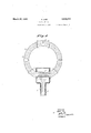
- Figure 1 shows awell known weatherproof direction finder aerial the windings w of y which (represented in dotted lines) are consists of the metal parts 6 and d and of a connecting piece 0 made of some insulating material.
- the ends f of the windings are connected to the receiver by way of the leads it running inside of the shaft 9.
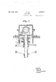
- FIG. 2 An example of an operating mechanism for tilting the frameaerial is depictedl in Figure 2; Only the lower part dof the? frame fingappearsoh the drawings which 5 represents a ivertical sectionof the tilting period, thus reducing to aminiplaced inside of a'frame tube.
- the latter a mechanism taken "in a plane at rightangles to' the-plane ofFi'gure I
- the tilting or re-erecting offthe frame are guided in "a vertical slot between twol strips fy' provided on the n'ecli gwhich forms,
- the'fr'ame aerial is iior'mally down'and the'shaf-t g,;'con- I handle being in ,its'upperposition.- 1
- the tostart'receptiontheaerialiframe iserected by operating; the'wheel 1".
- ln'turninggtheg wheelr ina'eertain direction one nut,'for in- V stancei 'ismoved downward, while the other the" shaft (Z in ia counterclockwise; direction and the; framerises'.
- theg'hanjdlet' is A turned down mafia engagesfthefstopmwhich isjjrdirefctly under it, hereby'shaftflq'isremay leased while the tilting mechanism is locked and the whole aerial may be turned as one solid unit around its vertical axis by operating the bearing wheel 8.
- I claimz v V 1.
- turewhen vin'use and to an unexposedposition when not 111 use includingy-a bearingrotatably V mounted on said structure, ashaftcarried by said bearing, a closure member rotatably mounted in said bearing, said closure-member in said bearing member, saidclosure member being adapted to enclose the conductors of said aerial system, means for rotating said closure member including differential Sgearl ng means, and'meansfo'r rotating said shaft.
- Anaerial system to be mounted on a structure and adapted to be moved ilnto an exposed position with reference to said structurewhen in use andto anunex-posed position when not inuse ncluding, a' bearing rot atably mounted onsai'd structu-re,.a shaft carried by a said bearing, a closure member rotatably mounted in saidbearingsaid closure member i being adapted to enclose the conductors of said aeri-al system, a hand wheel for rotating said shaft, ahand wheel tor rotating said closure member, said hand wheels being coaxially mountedadj-acenteach other;
- An aerial system to be mounted on a structure andmoved' into an exposed position with reference to sard'structure when in use t and to.anunexposed-position when not in use, a rotatable waterproof bearing member mounted in said structure and supported thereby, a hollow sh'aft fixedto said bearing member and adapted to be rotated-therewith,
Landscapes
- Pivots And Pivotal Connections (AREA)
Description
A. LEIB FRAME AERIAL March 22, 1932.
Filed Nov., 1929 2 Sheets-Sheet l INVENTOR AUGUST LEJB ATTORN EY v Patented Mar. 22,i:
A GUST umor iammmcmimnnrrassrenon r TELEFUNKENI.GESEIaLSCHAF'i'ilFU'RUt DRAHTLQSEVVTELEGRAPHIE, or BERLIN, GERMANY, "A CORPORATION or GERMANY" I Applicationflled November 5, 1929, Serial m: '4 d4.980',and in Ga a -music; 1929.
A direction finder aerial Consists, as known, of a number of windings in a vertical plane attached to a frame in such a way that they I may be rotated together with the frame about 5} a vertical axis.
The invention proposes to mprove this, frame aerial by .providing'a possibility oftilting it aboutza horizontal axis. This ar-" 0 rangement has the advantage that the aerial may be laid down, if desired, during thenon' reception mum the a1r resistance (which is particularly important in airplanes) and ofiering a very small target. l I j A particularly favorable and compact construction is secured in applying this principle to the well known frame aerial, located inside of a protective tube, when'the lower N part of the latter is made to function as the ,7 20. tilting shaft; With'this scheme a very favorable arrangement of the parts of the aeri als tilting mechanism is 'made possible, requlrmg but'a' restricted space. I
An example of such an arrangement inv accordance with the invention is illustrated on the drawings;
Figure 1 shows awell known weatherproof direction finder aerial the windings w of y which (represented in dotted lines) are consists of the metal parts 6 and d and of a connecting piece 0 made of some insulating material. The ends f of the windings are connected to the receiver by way of the leads it running inside of the shaft 9.
With the usual construction of the weather proof direction-finder aerial the shaft gis rigidly attached to the lower part of the pro tective tube. Accordingto the invention this construction is replaced by one in which the upper end of .shaftgserves as abearing e on which the lower part (i of-the frame ring is pivoted. j This arrangement affords the possibility of tilting the frame aerial at will about the axis d. I
An example of an operating mechanism for tilting the frameaerial is depictedl in Figure 2; Only the lower part dof the? frame fingappearsoh the drawings which 5 represents a ivertical sectionof the tilting period, thus reducing to aminiplaced inside of a'frame tube. The latter a mechanism taken "in a plane at rightangles to' the-plane ofFi'gure I The tilting or re-erecting offthe frame are guided in "a vertical slot between twol strips fy' provided on the n'ecli gwhich forms,
apart of bearing (3' Thus it 1s possible to {changethe vertical distance between" the nuts igand i by' turningthe'wheel'4 and thescrew attached to the wheel and equipped with two kinds of threads, one left-hand and'one a i 701 fastened toa base p which is stationary rela- I 'itive'tothedirection finder frame. 1 It is,how-
ever;ifpos'sible,to prevent the :shaft from turning byloperati'ng ahandle t attached to he neck g so thatit will engage acorrespond-v sing -stop a 'on'thebearing- 0;
In jadditiom'there 1s. another stop; "a at-' tached tothe wheel 1" which controls the tilt.
ing and re-erecting of the; aerial. This stop "offis solocated that ina certain position of the wheel, corresponding to the fully erected position of the aerial, it will come to lie; dl'.
r'ectly-underltherhandle'tl' Turning'thelatr V ter down releases the shaft 9, making-it free ito turn, whereas the, tilting mechanisirii of the aerial is now fixed, in regard to 'thefsh'aft.
During the non-reception periodthe'fr'ame aerial is iior'mally down'and the'shaf-t g,;'con- I handle being in ,its'upperposition.- 1 In order trolle'd bythe bearing wheels is fixedby fthe tostart'receptiontheaerialiframe iserected by operating; the'wheel 1". ln'turninggtheg wheelr ina'eertain direction one nut,'for in- V stancei 'ismoved downward, while the other the" shaft (Z in ia counterclockwise; direction and the; framerises'. theg'hanjdlet' is A turned down mafia engagesfthefstopmwhich isjjrdirefctly under it, hereby'shaftflq'isremay leased while the tilting mechanism is locked and the whole aerial may be turned as one solid unit around its vertical axis by operating the bearing wheel 8.
To lower the aerial upon termination of the reception the bearing wheel-sis turned until the handle 15 comes to lie directly under" u.
' Thereupon the handle is turnedup so that it engages u. Shaft g is now locked and the tilting me'chanism releasedi Turning the wheel r baclzward causes the nut it to mo've up and i to move down. The rope k engaging the projection Z turns the shaft d in a; clockwise directionand the aerial frameis turned down. V Y
I claimz v V 1. An aerial system t-o'be mounted ona structure and adapt-ed to be moved into an exposed position with reference to saidlstruomounted for rotation about its periphery in said bearing member, said closed member being adapted to enclose the conductors of said aerial system, means for rotating said closure member including a tensioned member fastoned at a point intermediateitslengthto said closed member, a sleeverha vingeoppo'sed pitch threads, a pair of threaded members on said sleeve, said threaded members being fastened to opposite ends of saidtensioned member,
and meansifor rotating said sleeve.
6. An arrangement, as claimed 1n claim 2,
in wliich said rotating means is coaxial with said shaft. 7
AUGUST LEIB.
turewhen vin'use and to an unexposedposition when not 111 use includingy-a bearingrotatably V mounted on said structure, ashaftcarried by said bearing, a closure member rotatably mounted in said bearing, said closure-member in said bearing member, saidclosure member being adapted to enclose the conductors of said aerial system, means for rotating said closure member including differential Sgearl ng means, and'meansfo'r rotating said shaft.
3. An arrangement, as claimed claim 2, in wh ch-rsaldrotat'mg means are co axia-l.
4. Anaerial system to be mounted on a structure and adapted to be moved ilnto an exposed position with reference to said structurewhen in use andto anunex-posed position when not inuse ncluding, a' bearing rot atably mounted onsai'd structu-re,.a shaft carried by a said bearing, a closure member rotatably mounted in saidbearingsaid closure member i being adapted to enclose the conductors of said aeri-al system, a hand wheel for rotating said shaft, ahand wheel tor rotating said closure member, said hand wheels being coaxially mountedadj-acenteach other;
I 5. An aerial system to be mounted on a structure andmoved' into an exposed position with reference to sard'structure when in use t and to.anunexposed-position when not in use, a rotatable waterproof bearing member mounted in said structure and supported thereby, a hollow sh'aft fixedto said bearing member and adapted to be rotated-therewith,
a weatherproof closed cylindrical member
Applications Claiming Priority (1)
| Application Number | Priority Date | Filing Date | Title |
|---|---|---|---|
| DE1850112X | 1929-01-16 |
Publications (1)
| Publication Number | Publication Date |
|---|---|
| US1850112A true US1850112A (en) | 1932-03-22 |
Family
ID=7745962
Family Applications (1)
| Application Number | Title | Priority Date | Filing Date |
|---|---|---|---|
| US404980A Expired - Lifetime US1850112A (en) | 1929-01-16 | 1929-11-05 | Frame aerial |
Country Status (1)
| Country | Link |
|---|---|
| US (1) | US1850112A (en) |
-
1929
- 1929-11-05 US US404980A patent/US1850112A/en not_active Expired - Lifetime
Similar Documents
| Publication | Publication Date | Title |
|---|---|---|
| US2027393A (en) | Cathode ray device | |
| US1747664A (en) | Apparatus for automatically training guns, etc., on moving objects | |
| US2476469A (en) | Adjustable antenna | |
| US2583210A (en) | Manually rotatable directional antenna | |
| US1957240A (en) | Control system | |
| US4093937A (en) | Automatic runway traffic direction control | |
| US2323064A (en) | Floating automatic signaling apparatus | |
| US1850112A (en) | Frame aerial | |
| US2542975A (en) | Erecting mechanism for reducing turn errors in vertical gyroscopes | |
| US2272213A (en) | Antenna reeling system | |
| US1525783A (en) | Teledynamic system for guide lights | |
| US2939335A (en) | Antenna rotating apparatus | |
| US2378563A (en) | Protecting apparatus | |
| US1952326A (en) | Short wave signaling apparatus | |
| US2251418A (en) | Aircraft antenna | |
| US3008140A (en) | Means for independent orientation of antennas on a mast | |
| US2095208A (en) | Landing indicator for airports | |
| US2711527A (en) | Directional control mechanism for antennas | |
| US2249836A (en) | Remote control mechanism | |
| GB216578A (en) | Improvements in frame aerials | |
| GB1042828A (en) | Antenna assembly | |
| US3722840A (en) | Spin stabilized vehicle and solar cell arrangement therefor | |
| US1892758A (en) | Direction finder | |
| US1912928A (en) | Direction indicating beacon | |
| US1856223A (en) | Antenna reel |