US1846292A - Hot air heating plant - Google Patents
Hot air heating plant Download PDFInfo
- Publication number
- US1846292A US1846292A US261775A US26177528A US1846292A US 1846292 A US1846292 A US 1846292A US 261775 A US261775 A US 261775A US 26177528 A US26177528 A US 26177528A US 1846292 A US1846292 A US 1846292A
- Authority
- US
- United States
- Prior art keywords
- air
- chamber
- heat
- heat chamber
- pipes
- Prior art date
- Legal status (The legal status is an assumption and is not a legal conclusion. Google has not performed a legal analysis and makes no representation as to the accuracy of the status listed.)
- Expired - Lifetime
Links
- 238000010438 heat treatment Methods 0.000 title description 55
- 239000007789 gas Substances 0.000 description 50
- 241000196324 Embryophyta Species 0.000 description 39
- 238000002485 combustion reaction Methods 0.000 description 34
- 239000000446 fuel Substances 0.000 description 24
- 238000004140 cleaning Methods 0.000 description 19
- 239000012530 fluid Substances 0.000 description 16
- XLYOFNOQVPJJNP-UHFFFAOYSA-N water Substances O XLYOFNOQVPJJNP-UHFFFAOYSA-N 0.000 description 16
- 238000005192 partition Methods 0.000 description 13
- 239000000567 combustion gas Substances 0.000 description 6
- 238000007599 discharging Methods 0.000 description 6
- 229920002892 amber Polymers 0.000 description 5
- 206010022000 influenza Diseases 0.000 description 4
- 239000000463 material Substances 0.000 description 3
- 230000004048 modification Effects 0.000 description 3
- 238000012986 modification Methods 0.000 description 3
- 239000000779 smoke Substances 0.000 description 3
- 102100035683 Axin-2 Human genes 0.000 description 2
- 101700047552 Axin-2 Proteins 0.000 description 2
- 238000010276 construction Methods 0.000 description 2
- 238000007598 dipping method Methods 0.000 description 2
- 239000000428 dust Substances 0.000 description 2
- 230000001965 increasing effect Effects 0.000 description 2
- 230000033001 locomotion Effects 0.000 description 2
- 239000007787 solid Substances 0.000 description 2
- 239000002699 waste material Substances 0.000 description 2
- 241000218652 Larix Species 0.000 description 1
- 235000005590 Larix decidua Nutrition 0.000 description 1
- 241001618237 Peltophorum africanum Species 0.000 description 1
- 235000017276 Salvia Nutrition 0.000 description 1
- 241001072909 Salvia Species 0.000 description 1
- 230000035508 accumulation Effects 0.000 description 1
- 238000009825 accumulation Methods 0.000 description 1
- 239000002253 acid Substances 0.000 description 1
- 238000007664 blowing Methods 0.000 description 1
- 239000011449 brick Substances 0.000 description 1
- 239000003245 coal Substances 0.000 description 1
- 239000000571 coke Substances 0.000 description 1
- 230000000694 effects Effects 0.000 description 1
- 230000003028 elevating effect Effects 0.000 description 1
- VKYKSIONXSXAKP-UHFFFAOYSA-N hexamethylenetetramine Chemical compound C1N(C2)CN3CN1CN2C3 VKYKSIONXSXAKP-UHFFFAOYSA-N 0.000 description 1
- 239000012535 impurity Substances 0.000 description 1
- 238000009434 installation Methods 0.000 description 1
- 230000001788 irregular Effects 0.000 description 1
- 239000007788 liquid Substances 0.000 description 1
- 239000002184 metal Substances 0.000 description 1
- 239000002245 particle Substances 0.000 description 1
- 229920000136 polysorbate Polymers 0.000 description 1
- 238000009877 rendering Methods 0.000 description 1
- 230000000630 rising effect Effects 0.000 description 1
- 239000004449 solid propellant Substances 0.000 description 1
- 210000003462 vein Anatomy 0.000 description 1
- 239000002023 wood Substances 0.000 description 1
Images

Classifications
-
- F—MECHANICAL ENGINEERING; LIGHTING; HEATING; WEAPONS; BLASTING
- F24—HEATING; RANGES; VENTILATING
- F24H—FLUID HEATERS, e.g. WATER OR AIR HEATERS, HAVING HEAT-GENERATING MEANS, e.g. HEAT PUMPS, IN GENERAL
- F24H3/00—Air heaters
- F24H3/02—Air heaters with forced circulation
- F24H3/06—Air heaters with forced circulation the air being kept separate from the heating medium, e.g. using forced circulation of air over radiators
- F24H3/08—Air heaters with forced circulation the air being kept separate from the heating medium, e.g. using forced circulation of air over radiators by tubes
- F24H3/087—Air heaters with forced circulation the air being kept separate from the heating medium, e.g. using forced circulation of air over radiators by tubes using fluid fuel
-
- Y—GENERAL TAGGING OF NEW TECHNOLOGICAL DEVELOPMENTS; GENERAL TAGGING OF CROSS-SECTIONAL TECHNOLOGIES SPANNING OVER SEVERAL SECTIONS OF THE IPC; TECHNICAL SUBJECTS COVERED BY FORMER USPC CROSS-REFERENCE ART COLLECTIONS [XRACs] AND DIGESTS
- Y10—TECHNICAL SUBJECTS COVERED BY FORMER USPC
- Y10S—TECHNICAL SUBJECTS COVERED BY FORMER USPC CROSS-REFERENCE ART COLLECTIONS [XRACs] AND DIGESTS
- Y10S261/00—Gas and liquid contact apparatus
- Y10S261/34—Automatic humidity regulation
Definitions
- My invention relates to furnaces for hot air heating plants and has for its object to provide a novel arrangement of heat chamber, combustion discharge passageways and air passageways such that the heat generated by fluid fuel burners (oil burners, gas burners and the like) will practically all of it be taken up by the air passing through the furnace before the combustion gases finally leave the same.
- fluid fuel burners oil burners, gas burners and the like
- This arrangement is such that the gases of combustion circulating in these passages ust prior to withdrawal from the furnace to the stack are at their lowest temperatures, so that the outer surfaces of these pipes or passages are contacted with the cold air coming to the furnace, the relative difference in the temperatures between incoming air and combustion gas discharge pipes being such that heat units are here abstracted even though the furnace gases have been reduced to a comparatively low temperature.
- ther objects of my invention are to provide a hot-air furnace of small size in proportion to its heat transferring capacity which shall be rectangular in cross section in planes parallel to all of its walls; to construct this furnace of sheet metal welded or otherwise secured together to be gas-tight and to be made at moderate cost; .to control the operation of the fluid fuel burner and the fan by means of a thermostat, and to synchronize the operation of fuel burner and fan so that the fuel burner will begin to operate ahead of the fan and the fan will continue to operate'a desired period after termination of operation of the fuel burner; to provide simple closures rendering easy of access for cleaning or other purposes all parts of the interior of the furnace which may need to be got at; to provide means for mamtaining a supply of water in the moistenfuel burners, i. e., furnaces burning coal,
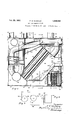
- Fig. 1 is a longitudial section through the oenter'of the furnace.
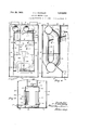
- Fig. 2 is a sectional plan on line 2-2 of Fig. 1 viewed in the direction of the arrows.
- Fig. 3 is a corresponding sectional plan on line 3-3 of Fig. 1 viewed in the direction of the arrows.
- Fig. 4 is a fragmentary sectional plan view on line 4-4 of Fig. 1 viewed in the direction of the arrows
- Fig. 5 is a transverse sectional elevation taken on line 5-5 of Fig. 1 viewed in the direction of thearrows.
- Fig. 6 is a part of the longitudinal sectional elevation similar to the part shown taken on line 6-6 of Fig. 2 and viewed in the direction of the arrows with the fan omitted.
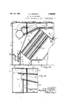
- Fig. 7 is a transverse sectional elevation view of part anism.
- Fig. 11 is a to plan sectional view of a portion of the Fig. 10.
- the outer parts of my furnace comprise a casing having top and bottom walls 10 and 11, side walls 12 and 13 and end walls 14 and 15. It will be noted that this outer casin embodies sixrectan lar walls connects together so that the ody of the furnace is rectangular in cross section along its horizontal, and itstransverse and longitudinal vertical planes, a matter of great utility in the shipping, handling and installation of such furnaces.
- a transverse partition 16 extends from top to bottom along one end of this outer casin and from side to side forming a closed inta e chamber 17 which is adaptto receive the air to be heated from pipes 18 which constitute the cold air return pipes urnace as shown in leading down from the difierent rooms to be heated.
- a transverse horizontal partition 19 divides this intake chamber into ,two parts and is provided with a central aperture 20 over which is a fan andfan casing 21 operated by an electric motor 22.
- a heat chamber 23, roughly. hexagonal in longitudinal vertical cross section, as clearly shown in Figs. 1 and 10, has its rear wall formed by the partition 16, upper walls by partitions 24 and 25, lower walls by partitions 26 and 27, front burner opening wall by partition 28 and side walls by partitions 29 and 30.
- the heat chamber top wall 2 1 extends beyond the wall 25, as indicated at 31 in Fig. 1, parallel with and spaced from the outside top wall 10, forming an upper air delivery chamber 32.
- the side walls 29, 30 of the heat chamber are spaced from the outside walls 12, 13 forming vertical passageways 33, 34
- the air is thus given a gyratory or cyclonic motion withinthe chamber 45 and it leaves the chamber through an opening 50, discharging into the chamber 35 which extends below the heat chamber 23 and connects with the side passageways 33 and 34 which lead to the hot air discharge chamber 32.
- Extending from the lower part of the intake chamber 17 and from the lower part of the heat chamber 23 are a multiplicity of pipes 51 which conduct the air across the heat chamber from the lower part thereof to the upper part, said pipes discharging into the air-receiving chamber 39, all as clearly shown in Fig. 1.
- the air is caused to rotate in the chamber 45.
- Water is automatically fed into the bottom of chamber 45 through a pipe 52, which keeps the water in the bottom of the chamher at a constant level as indicated at 53.
- a burner 61 for 011 or gas'of any desirable and known type is supported with feed of air and fuel extendin through the door 38, as indicated at 62.
- T e burner is provided with a downwardly-turned nozzle 63 of a well-known type whereby a flame indicated at 64 is directed' downwardly substantially parallel with the angularly-dispose'd bottom wall 26 and is blown against a plate 65 of fire brick or other refractoryv material.
- Fig. 1 and at 71 and 72 of Fig. 2 into substantially horizontal smoke pipes 73 and 74.
- Said pipes 73 and 74 extend through the front casing wall 15 and are provided with removable closures 75 and 76 by which ready access to said pipes is had for cleaning them should that at any time become necessary.
- Thepipe 7 3 passes throughthe wall 16 into the air intake chamber 17 and makes a T- connection at 77 with a vertical pipe 78 located close to the wall 16, which pipe connects with an-enlarged horizontal pipe 79 extending across the lower part of the airintake chamber 17, as clearly shown in Figs. 1 and 6.
- Pipe 74 is carried downwardly and curved over to make a union with a vertical pipe 80 in the air-intake chamber 17 and adjacent the other wall 14 thereof, which pipe 80 is united with ipe 79 as clearly shown in Figs. 1 and3, t e pipes 78 and 80 being at one end of the air-intake chamber 17 adjacent the wall 12.
- the pipe 83 extends through the outer wall 12, as indicated at 84, going from there to the stack. Pipes 83 and 79 each extend through the wall 13 and are provided with closures 85 and 86, to permit access for cleaning.
- heating means in the air-receiving chamber 39 consisting of the pipes 68 and 69
- heating means in the air delivery chamber 32 consisting of the pipes 73 and 74 and connections from 68 and 69
- a very lar amount of heating'means in the air-inta e chamber 17 consisting of arts of pipes 73 and 74 and all of pipes 8, 80, 79, 81, 82 and 84.
- the ases of combustion in the air-intake cham r have been progressively cooled so that as they travel through pipes 79, 81, 82
- e operation of the burner 61 and the fan 21 or its motor 22 is automatically controlled by a thermostat in a well-known way.
- I provide means, however, for synchronizing the starting and stopping of the burner and the fan respectively so that the burner will start a deslred time ahead of the fan and the fan will continue to run after the burner becomes inoperative for the same length of time:
- This is accomplished by means of a motor 87 indicated in Fig. 8 of common construction which is operated by a thermostat in the well-known way.
- This motor is provided with a pair of cam members 88 and 89 which are shown in detail in Fig. 9. They are oppositely disposed, although rotating in the same direction.
- Switch operators 990 and 91 engage the cam surfaces and are shown in the position where the switches are open and both instrumentalities inoperative.
- the burner circuit is indicated by the reference numeral 92 and the fan circuit by reference numeral 93.
- the motor is set to turn the cams one complete half turn for each actuation, and the time of making this half turn may, of course,-be determined in a well-known way, from one to three minutes being a suitable time for the purpose desired. Taking the cams as they are shown set in Fig. 1 it will be apparent that immediately upon operation contact will be made to set the burner apparatus in operation, but that contact to set the fan in operation will not take place until the cams have completed their half turn. The reverse result will follow the next actuation.
- the wall 16 is bent as indicated at 110 and again at 111, to be carried forward across the flush ends of the pipes 51 which, in this modification, may conveniently be made more numerous.
- no central horizontal partition across chamber 17, such as artition 19, is emplo ed.
- a vortica partition 112 exten s in arallel relation to the rear wall 14 to the casing and is united at 111 with partition 16.
- a central opening 113 is provided in the partition 112 throughwhich air is blown from a fan 114, having its drive shaft 115 horizontal instead of vertical as is true of the drive shaft of fan 21.
- thermoelectric heating plant comprising a casing iorming a central heat chamber, an air intake chamber, an air receiving chamber,
- each of said chem hers having part-oi its walls termed of heat chamber walls, and means for conducting air hnm the intake chamber across the heat chamber and through each oi said other chambers in succession,
- hot air heating plant comprising a casin forming a heat chamber, an air intake cham her, an air receiving chamber and an air delivery chamber, a fluid incl burner for directing a flame into said heat chamber, and pipes extending through the air receiving chamber, the air delivery chamber and the air intake chamber, said pipes being arranged to convey the products of combustion successively through said chambers in the order stated.
- a hot air heating plant comprising a casing iorming a heat chamber, an air intake chamber, and an air delivery chamber, a fluid fuel burner for directing a flame into said heat chamber, and a multiplicity of pipes extending from said heat chamber throu h the air delivery chamber and the air inta e chamber for conducting away gases of. combustion. 4
- a hot air heating plant comprising a casing forming a heat chamber and air passagcways, including an air intake passageway, a fluid fuel burner for directing a flame into said heat chamber, and means including a pipe in said air intake chamber for conducting away the gases of combustion.
- a hot air heating plant comprising a casing forming a heat chamber and air passageways including an intake passageway and air pipes extending across the heat chamber, a fluid fuel burner for directing a. flame into said heat chamber, means for conductin the gases of combustion from said heat c amber and through said air passagecessively to pass along one end of theheat chamber, across the heat chamber, along another end of the heat chamber, under the heat chamber, along its sides and above its top.
- a hot air heating plant comprising a casing forming a heat chamber and air passageways, arranged so as to conduct air through said passageways to cause the air successively to pass along one end of the heat chamber, across the heat chamber. along another end of the heat chamber, under the heat chamber, along its sides and aboveits top, and a fan for forcing the air through said pas sages and discharging it above the heat chamber.
- a hot air heating plant comprising a casing forming a central heat chamber and air-conducting passageways including passageways extending within and across the upper portion of the heat chamber and other passageways along the outside of all the walls oi the heat chamber, and means 'for causing an to travel successively through all said passageways.
- a hot air heating plant comprising a casing forming an interior heat chamber and air passages surrounding the same for conducting the air, said heat chamber being roughly hexagonal in shape, a fluid fuel Wit burner, and means for directing the flame each other and to the casing so as to cause said gases of combustion to form a Whirl in the heat chamber.
- a casing forming it heat chamber an passages for causing the air to pass around said heat chamber, means for forcing said air through said passa eways, a cleanin and moistening cham er forming part 0 said passages comprising means for causing the air. to whirl therein, and a wick for moisteningthe air.
- a hot air heating plant comprising a casing forming a central heat chamber, an air intake chamber, an air receiving chamber and an air delivery chamber, each of said chambers having part of its walls formed by walls of the heat chamber for heating air therein, and additional means for conducting gases of combustion through each of said air chambers for additionally heating said air.
- a hot'air heating plant comprising a casing forming a central heat chamber, an air intake chamber, an air receiving chamber and an air delivery chamber, each of said chambers having part of its walls formed b walls of the heat chamber for heating air t erein additional means for conductmg ases combustion through each of said air 0 ambers for additionally heating said air and a battery of pipes extending across said heat chamber for conducting an from the air intake chamber to the air delivery chamber.
- a hot air heating plant comprising a casing forming a central heat chamber, an air intake chamber, an air receiving chamber and an air delivery chamber, each of said chambers having part of its walls formed by walls of the heat chamber for heating air therein, additional means for conducting gases of combustion through each of said air chambers for additionally heating said air, and a fan in said intake chamber for causing a forced draft of air through each of said chambers inssuccession.
- a hot air heating plant comprising a casing forming a central heat chamber, an air intake chamber, an air receiving chamber and an air delivery chamber, each of said chambers having part of its walls formed by walls of the heat chamber for heating air therein, additional means for conducting gases of combustion through each of said air chambers for additionally heating said air, a battery of pipes extending across said heat chamber for conducting air from the air intake chamber to the air delivery chamber, and a fan in said intake chamber for causing a forced draft of air from said intake chamber through said pipes and through each of said other chambers in succession.
- a hot air heatin plant comprising a casing forming a heat 0 amber and an air intake chamber, said air intake chamber having part of its walls formed by walls of the heat chamber, and means for conducting gases of combustion through said intake chamber for.
- a hot air heating plant comprising a casing forming a central heat chamber, an air intake chamber, an air receiving chamber and an air delivery chamber, each of said chambers having part of its walls formed by walls of the heat chamber for heating air therein, additional means for conducting gases of combustion through each of said air chambers for additionally heating said air, and a fluid fuel burner for applying flame and heat into said heat chamber under forced draft to cause the same to im in upon and wipe all walls of said heat 0 am er.
- a hot air heating plant comprising an outer rectangular casing and an inner casing forming a heat chamber, all of whose walls are spaced from the walls of the outer casing to form chambers and passages for heating air, said chambers and passages being con- 18.
- a hot air heating plant comprising an outer rectangular casing and an inner casing forming a heat chamber, all of whose Walls are spaced from the walls of the outer casing to form chambers and passages for heating air, said chambers and passages being connected to cause the air to travel about all walls of said heat chamber, andsmoke flues extending within the chambers above and at each end of said heat chamber.
- a hot air heating plant comprising a casing, formin a central heat chamber, an air intake cham er, an air receiving chamber, and an air delivery chamber, and a fluid fuel burner for applying flame and heat into said heat chamber under forced draft so as to cause the same to impinge upon and wipe all walls of said heat chamber.
- a casing forming a heat chamber and passages for conducting the air around said heat chamber, means for, forcing the air through said passageways, andan air cleaning chamber forming part of said passageways comprising means for causing the air to whirl therein.
- a casing forming a heat chamber and passages for conducting the air around said heat chamber, means for forcing the air through said passagewa s, an
- said sageways comprising means for causing the air to whirl therein, a water pan in said air cleamng chamber, means for maintaining water at a fixed level therein, and a wick in the air-cleaning chamber having an end dipping into the water in the pan.
- a casing forming a heat chamber and passages for conductin air around said heat chamber to a point 0 dischar e therefrom, part of said passages being ormed into a circular air-cleaning chamber, having walls formed with tangential vanes for causing air moved through the air-cleaning chamber to rotate therein, and a fan for moving the air.
- a casing forming a heat chamber and passages for conducting air around said heat chamber to a point of discharge therefrom, part of said passages being formed into a circular air-cleaning chamber, having walls formed with tangential vanes tor causing air moved through the air-cleaning chamber to rotate therein, a fan tor moving the air, a water an in the bottom of the air-cleaning cham er, and means tor maintaining water in the pan at a constant level.
- a casing in a heating plant, a casing forming heat chamber and passages tor conducting air around said heat chamber to a point oi discharge therefrom, part of said passages being formed into a circular air-cleaning chamber, having walls termed with tangential vanes for causing air moved through the uincleaning chamber to rotate'therein, a tan tor moving the air, a water pan in the bottom of the air-cleanin chamber, and a wick positioned vertically a ovc and dipping into the water of the pan.
- a casing in a heating plant, forming a heat chamber and passages for conducting air about said heat chamber from the inlet point in said passages to the point of dis, charge therefrom, means to move said air therethrough in a continuous stream, said air being progressively heated as it is moved, and means in the passages located toward the discharge point therefrom for moistening said moving stream of air after it has been substantially heated.
- a casing forming a heat chamber and passages for conducting air about said heat chamber, including a multiplicity of pipes extending across a part of the heat chamber, and a moistening device located in said first-named passages beyond the point where the air is discharged from said pipes, in the path of movement of all air moving through said passages.
- a hot air heating plant comprising a casing forming. a heat chamber and passages for conducting air around said heat chamber to a point of discharge from the casing, a fan for moving the air, a fluid fuel burner, means including electric circuits and switch controls for operating the fan and the burner,-and thermostat-controlled means for operating the respective switch controls at predeterminedly separated times.
- a hot air heating plant comprising a casing forming a heat chamberand passa es for conducting air around said heat chain 1 to a point of discharge from the casing, a fan for moving the air, a fluid fuel burner, means including electric circuits and switch controls for operating the fan and the bumer, thermostat-contro led means for operating the burner switch control first and thereafter operating the fan switch control at a predetermined later interval of time.
- a hot-airheating plant comprising a casing torming an interior heat chamber and.
- a hot-air heating plant comprising a casing forming an interior heat chamber and air-conducting passages surrounding the same, the heat chamber havin parallel side walls and a multiplicity of en top and bottom walls angularl disposed so as to form a heat chamber 0 irregular longitudinalvertical cross-section, a battery of pi s extending across said heat chamber to orm a connection between twoof said passages, a
- fluid fuel burner positioned to direct the flame and combustion gases therefrom into said chamber and across and over said ipes, and means for dischar ing the gases 0 combustion from the chamber positioned so as to cause said gases of combustion to move back across and over said pipes and along said parallel side walls.
- a hot-air heating plant comprising a casing forming an interior heat chamber and air-conducting passages surrounding the same, said heat chamber being of extensive longitudinal-vertical cross-section, a fluid fuel burner positioned to direct the flame and combustion gases therefrom'in one direction within the chamber, and means for discharging the gases of combustion positioned to cause said ases to move in another direction, said directing and discharging means being positioned relatively to each other and to the casing so as to cause said gases of combustion to reverberate and form a whirl in the heat chamber and wipe the heat-chamber walls of said surrounding passages.
- a hot-air heating plant comprising a casing forming an interiorheat chamber and air-conducting passages at the ends thereof, a battery of pipes extending across said heat 1 chamber to form a connection between said passa e leaving substantial portions of said heat 0 amber on each side of the pipes, a fluid fuel burner positioned to direct flame and gases of combustion against the undersides of i said pipes and to cause it to pass across and over thebatter and into the space at the other sides of t e pi es, and means for discharging the gases 0 combustion positioned to cause the same to move from said space back across and over the ipes.
- a hot-air heating plant comprising a 2 casing forming a heat chamber and air passageways including an air intake passageway, a uid fuel burner for directing a flame into said heat chamber, means including a pipe in said air intake chamber for conducting 80 away the gases of combustion, and a fan in said air intake chamber for drawing intake air over said pipe and forcing it through the other air passageways.
- a casing forming a 35 heat chamber and passages for conducting the air around said heat chamber, means for forcing the air through said passageways, an air cleaning chamber forming a part of said passageways, means for maintaining a '40 Water surface at a fixed level to form the bottom of said air cleaning chamber, and means in the air cleaning chamber for causing the air to whirl therein and to impinge while whirling upon said water surface.
Landscapes
- Engineering & Computer Science (AREA)
- Physics & Mathematics (AREA)
- Thermal Sciences (AREA)
- Chemical & Material Sciences (AREA)
- Combustion & Propulsion (AREA)
- Mechanical Engineering (AREA)
- General Engineering & Computer Science (AREA)
- Combustion Of Fluid Fuel (AREA)
Description
Feb. 23, 1932. A, WHITELE; 1,846,292
HOT AIR HEATING PLANT Original Filed March 15, 1928 4 Sheets-Sheet l Hy' 9 so I In van for- F4 W/u'teie 39w aka/Ml; Kttorneys.
Feb. 23, 1932. wHlTELEY 1,846,292
HOT AIR HEATING PLANT Original Filed March 15, 1928 4 Sheets-Sheet 2 I 6 I I n ven for:
- Whiteley Feb. 23, 1932. F. A. WHITELEY HOT AIR HEATING PLANT Original Filed March 15, 1928 4 Sheets-Sheet 3 In van for: f. '4 Whiteley 9 a a,
flitorn egs.
Feb. 23, 1932. A, wHn- 1,846,292
HOT AIR HEATING PLANT Original Filed March 15, 1928 4 Sheets-Sheet 4 Inventor-.- 2 /1 Whiteley.
, /{l"i'qrneys.
Patented m. 23,1932
UNITED STATES PATENT OFFICE FRANK A; WHITELEY, OI MINNEAPOLIS, IINIENTL HOT HEATING PLAN! Application filed larch 15, 188 8 Serial Io. 281,775. Renewed Kay 14, 1981.
My invention relates to furnaces for hot air heating plants and has for its object to provide a novel arrangement of heat chamber, combustion discharge passageways and air passageways such that the heat generated by fluid fuel burners (oil burners, gas burners and the like) will practically all of it be taken up by the air passing through the furnace before the combustion gases finally leave the same.
I accomplish this object by providing a relatively long travel for the air being heated as it passes from the intake chamber to the discharge chamber and at the same time providing an excessively large area of heated surfaces over which said air is caused to pass whereby all of said heat is abstracted and delivered to the hot air pipes leading from the discharge chamber. It is an object of my invention to provide means for drawing the air under negative pressure into the intake chamber and for forcing it therefrom through the various passage-ways and chambers to the hot air pipes from the discharge cham' her and thence to the rooms to be heated. lit is a further object of my invention to form the intake chamber as a part of the furnace proper adjacent one wall thereof and to form in said intake chamber a system of flues or pipes for final discharge of the gases of combustio'n. This arrangement is such that the gases of combustion circulating in these passages ust prior to withdrawal from the furnace to the stack are at their lowest temperatures, so that the outer surfaces of these pipes or passages are contacted with the cold air coming to the furnace, the relative difference in the temperatures between incoming air and combustion gas discharge pipes being such that heat units are here abstracted even though the furnace gases have been reduced to a comparatively low temperature.
It is a further object of my invention to provide a central heat chamber roughly circular or hexagonal in its longitudinal cross section in combination with a fluid fuel burner adapted to direct a flame downwardly in the heat chamber, and with means for withdrawing the furnace gases at points above the burner on both sides of the heat chamber so that the gases in the heat chamber will be caused to whirl or rotate in planes oneach side of the burner; and to provide a multiplicity of air passages extending across said rotating whirls of furnace gases. It is a further ob'ect of myinvention to provide, in connectlon with this central heat chamberand crossing air passageways, an air intake chamber delivering to said passagewaysnear the bottom of the furnace, an air-recelving chamber receiving the air from said passageways near the top of the furnace, an aumoistening and purifying chamber at the front and lower part of the furnace, and an air-delivery chamber at the top of the furnace together with passageways connecting all of said chambers, all of said chambers and all of said passageways having walls or part of their walls exposed to-the gases in the heat chamber. It is a further ob ect of my invention to discharge the furnace gases through a multiplicity of flues extending through the air-receiving chamber, the air-discharge chamber and the air-intake chamber. It is a further object of my invention to provide air-moistening and cleaning means whereby the air as it passes through the air-moistenin and cleaning-chamber is freed from dust and solid impurities and is impregnated with a re uisite amount of moisture.
ther objects of my invention are to provide a hot-air furnace of small size in proportion to its heat transferring capacity which shall be rectangular in cross section in planes parallel to all of its walls; to construct this furnace of sheet metal welded or otherwise secured together to be gas-tight and to be made at moderate cost; .to control the operation of the fluid fuel burner and the fan by means of a thermostat, and to synchronize the operation of fuel burner and fan so that the fuel burner will begin to operate ahead of the fan and the fan will continue to operate'a desired period after termination of operation of the fuel burner; to provide simple closures rendering easy of access for cleaning or other purposes all parts of the interior of the furnace which may need to be got at; to provide means for mamtaining a supply of water in the moistenfuel burners, i. e., furnaces burning coal,
coke or wood, in that the heat is all generated in a gas as combustion takes place and there is no residual heat-radiating'mass in the heat chamber. Building regulations require that the furnace gas passageways from oil burners or gas burners must not be obstructed by dampers or similar means to restrict the escape passageways. As a result, in furnaces of the type ordinarily employed for burning solid fuel, the gases of combustion of oil burners and gas burners have a comparatively short travel from the flame to the stack pipe; and that short distance is traversed with increased speed because nearly all burners of this type operate under forced draft, blowing the combustion air in with the fuel and gas. The result is that in furnaces as now generally used with oil burners and gas'burners, the gases of combustion leave the furnace at a high temperature and so ragidly that there is very great waste of heat. 0 much so, that they are markedly uneconomical in fuel consumption and, hence, operating cost. This, notwithstanding the manifold advantages of oil burners and gas burners, has greatly limited their use. It is the purpose of my 1nvention to so increase the length of travel of the gases of combustion, without in any way restricting their free egress to the stack pipe, and correspondingly increasing the gas heated surfaces exposed to the circulating air, as to withdraw nearly all the heat units from the burning gas or oil and thereby cut out the waste of heat accompanying the use of oil burners and gas burners so as to make them economically usable in a high degree.
In the drawings, illustrating a form of my invention,-
Fig. 1 is a longitudial section through the oenter'of the furnace. Fig. 2 is a sectional plan on line 2-2 of Fig. 1 viewed in the direction of the arrows. Fig. 3 is a corresponding sectional plan on line 3-3 of Fig. 1 viewed in the direction of the arrows. Fig. 4 is a fragmentary sectional plan view on line 4-4 of Fig. 1 viewed in the direction of the arrows Fig. 5 is a transverse sectional elevation taken on line 5-5 of Fig. 1 viewed in the direction of thearrows. Fig. 6 is a part of the longitudinal sectional elevation similar to the part shown taken on line 6-6 of Fig. 2 and viewed in the direction of the arrows with the fan omitted. Fig. 7 is a transverse sectional elevation view of part anism. Fig. 11 is a to plan sectional view of a portion of the Fig. 10.
The outer parts of my furnace comprise a casing having top and bottom walls 10 and 11, side walls 12 and 13 and end walls 14 and 15. It will be noted that this outer casin embodies sixrectan lar walls connects together so that the ody of the furnace is rectangular in cross section along its horizontal, and itstransverse and longitudinal vertical planes, a matter of great utility in the shipping, handling and installation of such furnaces. A transverse partition 16 extends from top to bottom along one end of this outer casin and from side to side forming a closed inta e chamber 17 which is adaptto receive the air to be heated from pipes 18 which constitute the cold air return pipes urnace as shown in leading down from the difierent rooms to be heated. A transverse horizontal partition 19 divides this intake chamber into ,two parts and is provided with a central aperture 20 over which is a fan andfan casing 21 operated by an electric motor 22. A heat chamber 23, roughly. hexagonal in longitudinal vertical cross section, as clearly shown in Figs. 1 and 10, has its rear wall formed by the partition 16, upper walls by partitions 24 and 25, lower walls by partitions 26 and 27, front burner opening wall by partition 28 and side walls by partitions 29 and 30. The heat chamber top wall 2 1 extends beyond the wall 25, as indicated at 31 in Fig. 1, parallel with and spaced from the outside top wall 10, forming an upper air delivery chamber 32. The side walls 29, 30 of the heat chamber are spaced from the outside walls 12, 13 forming vertical passageways 33, 34
extending along said side walls and opening at their tops into the air delivery chamber 32 41 is provided under the encased opening 36 so that downwardly extendinggair trunks 42, 43 are formed on either side of said circular casing. These air trunks are shut oil from the lower passageway 35 and the side assageways 33, 34 by a partition 44 which ulges around the circular casing 40, as clearly shown in Fig. 3. Air from trunk 42 enters the chamber 45 within the circular casing through a boxing 46, and air from trun 43 enters the chamber through the boxin 47. The bcxings 46 and 47 are provide with veins 48 tangentially disposed toward the casing 40 so as to provide a multiplicity of longitudinal openings 49 extending in opposite directions in the respective boxings. The air is thus given a gyratory or cyclonic motion withinthe chamber 45 and it leaves the chamber through an opening 50, discharging into the chamber 35 which extends below the heat chamber 23 and connects with the side passageways 33 and 34 which lead to the hot air discharge chamber 32. Extending from the lower part of the intake chamber 17 and from the lower part of the heat chamber 23 are a multiplicity of pipes 51 which conduct the air across the heat chamber from the lower part thereof to the upper part, said pipes discharging into the air-receiving chamber 39, all as clearly shown in Fig. 1.
The air is caused to rotate in the chamber 45. Water is automatically fed into the bottom of chamber 45 through a pipe 52, which keeps the water in the bottom of the chamher at a constant level as indicated at 53.
Any well-known means of controlling the.
'* up the body of water in chamber 45 so as to prevent its rotation. Suspended from a bar 56 toward the upper part of chamber 45 is a circular wicking 57, the lower part of which is held by a weighted ring 58 upon the disc 54 so that the lower art of said circular wicking will always e immersed in the Water in the chamber 45. In this manner the heated air will be caused to circulate rapidly in chamber 45 before it is discharged through opening 50 and will at the same time deposit in the water particles of dust, dirt and solid matter which it may carry, and will take up a requisite amount of moisture so that the air delivered to the rooms will be suitably moistened. A door 59 in the front casing Wall 15 and a separate door 60 which opens through cylindrical casing 40 and is adapted to be reached through said door 59 admit to the interior of chamber 45 for taking out the wicking so that fresh and clean wicks may be inserted, and for taking out the grid and disc 54 by which accumulations of dirt collected may be withdrawn. 1 1
In the front opening 36 a burner 61 for 011 or gas'of any desirable and known type is supported with feed of air and fuel extendin through the door 38, as indicated at 62. T e burner is provided with a downwardly-turned nozzle 63 of a well-known type whereby a flame indicated at 64 is directed' downwardly substantially parallel with the angularly-dispose'd bottom wall 26 and is blown against a plate 65 of fire brick or other refractoryv material. From this plate 65 the gases of'combustion will s read laterally and rearwardly, rotating in a road cyclone along the side walls of the heat c against the upper walls 24 and 25, leaving the heat chamber through flue openings 66 and 67 symmetrically disposed and positioned above and laterally spaced from said burner nozzle 63, as clearly shown in Fi 5.
a From the flue openings 66 and 67 smoke pipes 68 and 69 lead through the air-receiving chamber 39 and through partition 31, connecting by a T joint, as indicated at 70 of.
Fig. 1 and at 71 and 72 of Fig. 2, into substantially horizontal smoke pipes 73 and 74. Said pipes 73 and 74 extend through the front casing wall 15 and are provided with removable closures 75 and 76 by which ready access to said pipes is had for cleaning them should that at any time become necessary. Thepipe 7 3 passes throughthe wall 16 into the air intake chamber 17 and makes a T- connection at 77 with a vertical pipe 78 located close to the wall 16, which pipe connects with an-enlarged horizontal pipe 79 extending across the lower part of the airintake chamber 17, as clearly shown in Figs. 1 and 6. Pipe 74 is carried downwardly and curved over to make a union with a vertical pipe 80 in the air-intake chamber 17 and adjacent the other wall 14 thereof, which pipe 80 is united with ipe 79 as clearly shown in Figs. 1 and3, t e pipes 78 and 80 being at one end of the air-intake chamber 17 adjacent the wall 12. From the other end of pipe 79 in the intake chamber 17 and adjacent the wall 13 rise vertical pipes 81 and 82 which are connected with the horizontal smoke discharge pipe 83, as clearly shown in Figs. 2, 3 and 6. The pipe 83 extends through the outer wall 12, as indicated at 84, going from there to the stack. Pipes 83 and 79 each extend through the wall 13 and are provided with closures 85 and 86, to permit access for cleaning.-
From the above it will be seen that the gases of combustion after rotating in a great whirl in the roughly hexagonal heat chamber 23 pass in two streams through pipes 67, 73 and 78 and pipes 68, 74 and 80 to the common horizontal pipe 79, and through pipe 79 and duplicate elevating pipes 81, 82 to the stack amber, across and over the pipes 51 and I pipe 81. In all of this travel the walls of Gil the various pipes carrying the gases of combustion are exposed to the air bein heated and delivered from the furnace. here is thus, in addition to the walls of the heat chamber, heating means in the air-receiving chamber 39 consisting of the pipes 68 and 69, heating means in the air delivery chamber 32 consisting of the pipes 73 and 74 and connections from 68 and 69, and a very lar amount of heating'means in the air-inta e chamber 17 consisting of arts of pipes 73 and 74 and all of pipes 8, 80, 79, 81, 82 and 84. It is important to note, also, that the ases of combustion in the air-intake cham r have been progressively cooled so that as they travel through pipes 79, 81, 82
and 83 they are at their minimum temperature. But at this point they are subjected to air in the intake chamber, also at its minimum temperature, so that the difference in temperature between the incoming air and the surface of these pipes will still result in ra id withdrawal of heat units.
e operation of the burner 61 and the fan 21 or its motor 22 is automatically controlled by a thermostat in a well-known way. I provide means, however, for synchronizing the starting and stopping of the burner and the fan respectively so that the burner will start a deslred time ahead of the fan and the fan will continue to run after the burner becomes inoperative for the same length of time: This is accomplished by means of a motor 87 indicated in Fig. 8 of common construction which is operated by a thermostat in the well-known way. This motor is provided with a pair of cam members 88 and 89 which are shown in detail in Fig. 9. They are oppositely disposed, although rotating in the same direction. Switch operators 990 and 91 engage the cam surfaces and are shown in the position where the switches are open and both instrumentalities inoperative. The burner circuit is indicated by the reference numeral 92 and the fan circuit by reference numeral 93. The motor is set to turn the cams one complete half turn for each actuation, and the time of making this half turn may, of course,-be determined in a well-known way, from one to three minutes being a suitable time for the purpose desired. Taking the cams as they are shown set in Fig. 1 it will be apparent that immediately upon operation contact will be made to set the burner apparatus in operation, but that contact to set the fan in operation will not take place until the cams have completed their half turn. The reverse result will follow the next actuation.
In the modification shown in Figs 10 and 11, the wall 16 is bent as indicated at 110 and again at 111, to be carried forward across the flush ends of the pipes 51 which, in this modification, may conveniently be made more numerous. In this form no central horizontal partition across chamber 17, such as artition 19, is emplo ed. Instead a vortica partition 112 exten s in arallel relation to the rear wall 14 to the casing and is united at 111 with partition 16. A central opening 113 is provided in the partition 112 throughwhich air is blown from a fan 114, having its drive shaft 115 horizontal instead of vertical as is true of the drive shaft of fan 21. There are some advantages in usin a fan with a horizontal drive s aft instea of a vertical drive shaft. It will be apparent, however, thatso far as drawing the air from the intake chamber 17 and forcing it through the pipes 51 is concerned, fans 21 and 114 will operate in a similar manner.
In the modified form of Figs. 10 and 11,
While I have described and shown preferred embodiments of my invention in this specification and in the drawings accompanying it, I do not wish to be limited to precise details of construction, kinds of material, or forms or shapes of parts, since the invention may be embodied in structures differing in detail, form and material without departing from the spirit and scope of the invention.
The operation of the furnace will be apparent from the above description. When the cam is actuated power being available the from there through the trunks 42 and 43 into the chamber 45, where it will be freed from dirt and moistened. It will then pass into the passage way 35 and from there upthe side lit till
it'd
perature between the heat-receiving medium and the heating medium 18 relatively great. in some cases it may be desirable not to carry the iurnace gases into the lower part oi the airdntalie chamber '17, in which case connec :tions may be made directlybetween pipes Y3 and, 'l'land stack pipe 83, as indicated in Figs. lb and ill,
claim:
It. it hot air heating plant comprising a casing iorming a central heat chamber, an air intake chamber, an air receiving chamber,
an air moistening and cleaning chamber and an air delivery chamber, each of said chem hers having part-oi its walls termed of heat chamber walls, and means for conducting air hnm the intake chamber across the heat chamber and through each oi said other chambers in succession,
52.. it. hot air heating plant comprising a casin forming a heat chamber, an air intake cham her, an air receiving chamber and an air delivery chamber, a fluid incl burner for directing a flame into said heat chamber, and pipes extending through the air receiving chamber, the air delivery chamber and the air intake chamber, said pipes being arranged to convey the products of combustion successively through said chambers in the order stated.
3. A hot air heating plant comprising a casing iorming a heat chamber, an air intake chamber, and an air delivery chamber, a fluid fuel burner for directing a flame into said heat chamber, and a multiplicity of pipes extending from said heat chamber throu h the air delivery chamber and the air inta e chamber for conducting away gases of. combustion. 4
t. A hot air heating plant comprising a casing forming a heat chamber and air passagcways, including an air intake passageway, a fluid fuel burner for directing a flame into said heat chamber, and means including a pipe in said air intake chamber for conducting away the gases of combustion.
5. A hot air heating plant comprising a casing forming a heat chamber and air passageways including an intake passageway and air pipes extending across the heat chamber, a fluid fuel burner for directing a. flame into said heat chamber, means for conductin the gases of combustion from said heat c amber and through said air passagecessively to pass along one end of theheat chamber, across the heat chamber, along another end of the heat chamber, under the heat chamber, along its sides and above its top.
7: A hot air heating plant comprising a casing forming a heat chamber and air passageways, arranged so as to conduct air through said passageways to cause the air successively to pass along one end of the heat chamber, across the heat chamber. along another end of the heat chamber, under the heat chamber, along its sides and aboveits top, and a fan for forcing the air through said pas sages and discharging it above the heat chamber.
8. A hot air heating plant comprising a casing forming a central heat chamber and air-conducting passageways including passageways extending within and across the upper portion of the heat chamber and other passageways along the outside of all the walls oi the heat chamber, and means 'for causing an to travel successively through all said passageways. w
9 A hot air heating plant comprising a casing forming an interior heat chamber and air passages surrounding the same for conducting the air, said heat chamber being roughly hexagonal in shape, a fluid fuel Wit burner, and means for directing the flame each other and to the casing so as to cause said gases of combustion to form a Whirl in the heat chamber.
10. In a heatin plant, a casing forming it heat chamber an passages for causing the air to pass around said heat chamber, means for forcing said air through said passa eways, a cleanin and moistening cham er forming part 0 said passages comprising means for causing the air. to whirl therein, and a wick for moisteningthe air.
11. A hot air heating plant comprising a casing forming a central heat chamber, an air intake chamber, an air receiving chamber and an air delivery chamber, each of said chambers having part of its walls formed by walls of the heat chamber for heating air therein, and additional means for conducting gases of combustion through each of said air chambers for additionally heating said air.
12. A hot'air heating plant comprising a casing forming a central heat chamber, an air intake chamber, an air receiving chamber and an air delivery chamber, each of said chambers having part of its walls formed b walls of the heat chamber for heating air t erein additional means for conductmg ases combustion through each of said air 0 ambers for additionally heating said air and a battery of pipes extending across said heat chamber for conducting an from the air intake chamber to the air delivery chamber.
13. A hot air heating plant comprising a casing forming a central heat chamber, an air intake chamber, an air receiving chamber and an air delivery chamber, each of said chambers having part of its walls formed by walls of the heat chamber for heating air therein, additional means for conducting gases of combustion through each of said air chambers for additionally heating said air, and a fan in said intake chamber for causing a forced draft of air through each of said chambers inssuccession.
14. A hot air heating plant comprising a casing forming a central heat chamber, an air intake chamber, an air receiving chamber and an air delivery chamber, each of said chambers having part of its walls formed by walls of the heat chamber for heating air therein, additional means for conducting gases of combustion through each of said air chambers for additionally heating said air, a battery of pipes extending across said heat chamber for conducting air from the air intake chamber to the air delivery chamber, and a fan in said intake chamber for causing a forced draft of air from said intake chamber through said pipes and through each of said other chambers in succession.
15. A hot air heatin plant comprising a casing forming a heat 0 amber and an air intake chamber, said air intake chamber having part of its walls formed by walls of the heat chamber, and means for conducting gases of combustion through said intake chamber for.
heating the air therein additionally to the {:eating thereof by the walls of the heat cham- 16. A hot air heating plant comprising a casing forming a central heat chamber, an air intake chamber, an air receiving chamber and an air delivery chamber, each of said chambers having part of its walls formed by walls of the heat chamber for heating air therein, additional means for conducting gases of combustion through each of said air chambers for additionally heating said air, and a fluid fuel burner for applying flame and heat into said heat chamber under forced draft to cause the same to im in upon and wipe all walls of said heat 0 am er. v
17. A hot air heating plant comprising an outer rectangular casing and an inner casing forming a heat chamber, all of whose walls are spaced from the walls of the outer casing to form chambers and passages for heating air, said chambers and passages being con- 18. A hot air heating plant comprising an outer rectangular casing and an inner casing forming a heat chamber, all of whose Walls are spaced from the walls of the outer casing to form chambers and passages for heating air, said chambers and passages being connected to cause the air to travel about all walls of said heat chamber, andsmoke flues extending within the chambers above and at each end of said heat chamber.
19. A hot air heating plant, comprising a casing, formin a central heat chamber, an air intake cham er, an air receiving chamber, and an air delivery chamber, and a fluid fuel burner for applying flame and heat into said heat chamber under forced draft so as to cause the same to impinge upon and wipe all walls of said heat chamber.
20. In a heating plant, a casing forming a heat chamber and passages for conducting the air around said heat chamber, means for, forcing the air through said passageways, andan air cleaning chamber forming part of said passageways comprising means for causing the air to whirl therein.
21-. In a heating plant, a casing forming a heat chamber and passages for conducting the air around said heat chamber, means for forcing the air through said passagewa s, an
air cleaning chamber forming part 0 said sageways comprising means for causing the air to whirl therein, a water pan in said air cleamng chamber, means for maintaining water at a fixed level therein, and a wick in the air-cleaning chamber having an end dipping into the water in the pan.
23.'In a heating plant, a casing forming a heat chamber and passages for conductin air around said heat chamber to a point 0 dischar e therefrom, part of said passages being ormed into a circular air-cleaning chamber, having walls formed with tangential vanes for causing air moved through the air-cleaning chamber to rotate therein, and a fan for moving the air.
24. In a heating plant,- a casing forming a heat chamber and passages for conducting air around said heat chamber to a point of discharge therefrom, part of said passages being formed into a circular air-cleamng chamber, having walls formed with tangential vanes for causing air moved through the means:
air-cleaning chamber to rotate therein, a fan for movin the air, and a removable water pan in the ottom of said air-cleaning cham- 25. In a heating plant, a casing forming a heat chamber and passages for conducting air around said heat chamber to a point of discharge therefrom, part of said passages being formed into a circular air-cleaning chamber, having walls formed with tangential vanes tor causing air moved through the air-cleaning chamber to rotate therein, a fan tor moving the air, a water an in the bottom of the air-cleaning cham er, and means tor maintaining water in the pan at a constant level.
in a heating plant, a casing forming heat chamber and passages tor conducting air around said heat chamber to a point oi discharge therefrom, part of said passages being formed into a circular air-cleaning chamber, having walls termed with tangential vanes for causing air moved through the uincleaning chamber to rotate'therein, a tan tor moving the air, a water pan in the bottom of the air-cleanin chamber, and a wick positioned vertically a ovc and dipping into the water of the pan.
2?. in a heating plant, a casing forming a heat chamber and passages for conducting air about said heat chamber from the inlet point in said passages to the point of dis, charge therefrom, means to move said air therethrough in a continuous stream, said air being progressively heated as it is moved, and means in the passages located toward the discharge point therefrom for moistening said moving stream of air after it has been substantially heated.
28. In a heating plant, a casing forming a heat chamber and passages for conducting air about said heat chamber, including a multiplicity of pipes extending across a part of the heat chamber, and a moistening device located in said first-named passages beyond the point where the air is discharged from said pipes, in the path of movement of all air moving through said passages.
29. A hot air heating plant comprising a casing forming. a heat chamber and passages for conducting air around said heat chamber to a point of discharge from the casing, a fan for moving the air, a fluid fuel burner, means including electric circuits and switch controls for operating the fan and the burner,-and thermostat-controlled means for operating the respective switch controls at predeterminedly separated times.
30. A hot air heating plant comprising a casing forming a heat chamberand passa es for conducting air around said heat chain 1 to a point of discharge from the casing, a fan for moving the air, a fluid fuel burner, means including electric circuits and switch controls for operating the fan and the bumer, thermostat-contro led means for operating the burner switch control first and thereafter operating the fan switch control at a predetermined later interval of time.
31. A hot-airheating plant comprising a casing torming an interior heat chamber and.
air-conducting passages at the ends thereof a multiplicity of pipes extending across said heat chamber to form a connection between said passages, a fluid fuel burner positioned to direct the flame and combustion gases therefrom across and over said pipes and' into the top of the chamber, and means for disdharging the gases of combustion from the chamber positioned so as to cause said gases of combustion to move back across and over said pipes.
33. A hot-air heating plant comprising a casing forming an interior heat chamber and air-conducting passages surrounding the same, the heat chamber havin parallel side walls and a multiplicity of en top and bottom walls angularl disposed so as to form a heat chamber 0 irregular longitudinalvertical cross-section, a battery of pi s extending across said heat chamber to orm a connection between twoof said passages, a
fluid fuel burner positioned to direct the flame and combustion gases therefrom into said chamber and across and over said ipes, and means for dischar ing the gases 0 combustion from the chamber positioned so as to cause said gases of combustion to move back across and over said pipes and along said parallel side walls.
34. A hot-air heating plant comprising a casing forming an interior heat chamber and air-conducting passages surrounding the same, said heat chamber being of extensive longitudinal-vertical cross-section, a fluid fuel burner positioned to direct the flame and combustion gases therefrom'in one direction within the chamber, and means for discharging the gases of combustion positioned to cause said ases to move in another direction, said directing and discharging means being positioned relatively to each other and to the casing so as to cause said gases of combustion to reverberate and form a whirl in the heat chamber and wipe the heat-chamber walls of said surrounding passages.
- 35. A hot-air heating plant comprising a casing forming an interiorheat chamber and air-conducting passages at the ends thereof, a battery of pipes extending across said heat 1 chamber to form a connection between said passa e leaving substantial portions of said heat 0 amber on each side of the pipes, a fluid fuel burner positioned to direct flame and gases of combustion against the undersides of i said pipes and to cause it to pass across and over thebatter and into the space at the other sides of t e pi es, and means for discharging the gases 0 combustion positioned to cause the same to move from said space back across and over the ipes.
36. A hot-air heating p ant com rising a casing forming a heat chamber an air passageways including an air intake passageway, a uid fuel burner for directing a flame into g said heat chamber, and means including a lurality of horizontal pipes and connections tween the same in said air intake chamber for conducting away the gases of combustion. 37. A hot-air heating plant comprising a 2 casing forming a heat chamber and air passageways including an air intake passageway, a uid fuel burner for directing a flame into said heat chamber, means including a pipe in said air intake chamber for conducting 80 away the gases of combustion, and a fan in said air intake chamber for drawing intake air over said pipe and forcing it through the other air passageways.
38. In a heatin plant a casing forming a 35 heat chamber and passages for conducting the air around said heat chamber, means for forcing the air through said passageways, an air cleaning chamber forming a part of said passageways, means for maintaining a '40 Water surface at a fixed level to form the bottom of said air cleaning chamber, and means in the air cleaning chamber for causing the air to whirl therein and to impinge while whirling upon said water surface.
4a In testimony whereof I hereunto ailix my signature.
FRANK A. W'HITELEY.
Priority Applications (1)
| Application Number | Priority Date | Filing Date | Title |
|---|---|---|---|
| US261775A US1846292A (en) | 1928-03-15 | 1928-03-15 | Hot air heating plant |
Applications Claiming Priority (1)
| Application Number | Priority Date | Filing Date | Title |
|---|---|---|---|
| US261775A US1846292A (en) | 1928-03-15 | 1928-03-15 | Hot air heating plant |
Publications (1)
| Publication Number | Publication Date |
|---|---|
| US1846292A true US1846292A (en) | 1932-02-23 |
Family
ID=22994805
Family Applications (1)
| Application Number | Title | Priority Date | Filing Date |
|---|---|---|---|
| US261775A Expired - Lifetime US1846292A (en) | 1928-03-15 | 1928-03-15 | Hot air heating plant |
Country Status (1)
| Country | Link |
|---|---|
| US (1) | US1846292A (en) |
Cited By (2)
| Publication number | Priority date | Publication date | Assignee | Title |
|---|---|---|---|---|
| US2573364A (en) * | 1949-02-04 | 1951-10-30 | John E Scharff | Air-heating furnace with liquid heat transfer means |
| US2786632A (en) * | 1953-11-16 | 1957-03-26 | Honeywell Regulator Co | Control apparatus for forced air furnace |
-
1928
- 1928-03-15 US US261775A patent/US1846292A/en not_active Expired - Lifetime
Cited By (2)
| Publication number | Priority date | Publication date | Assignee | Title |
|---|---|---|---|---|
| US2573364A (en) * | 1949-02-04 | 1951-10-30 | John E Scharff | Air-heating furnace with liquid heat transfer means |
| US2786632A (en) * | 1953-11-16 | 1957-03-26 | Honeywell Regulator Co | Control apparatus for forced air furnace |
Similar Documents
| Publication | Publication Date | Title |
|---|---|---|
| US2363742A (en) | Furnace | |
| US1846292A (en) | Hot air heating plant | |
| US2157643A (en) | Oil-fired furnace | |
| US1334741A (en) | Air-heating structure | |
| US2529574A (en) | Direct fired hot-air heating apparatus | |
| US2130630A (en) | Air conditioning apparatus | |
| US2249554A (en) | All-weather hot air furnace | |
| US2290255A (en) | Furnace | |
| US2259187A (en) | Heating unit | |
| US1877223A (en) | Method of humidifying air | |
| US1371390A (en) | Heater | |
| US2512384A (en) | Direct-fired hot-air heating apparatus | |
| US601590A (en) | Stove or furnace | |
| US2240531A (en) | Furnace | |
| US1837485A (en) | Heating apparatus | |
| US752002A (en) | Heating apparatus | |
| US2311657A (en) | Vertical domestic heating unit | |
| US1788447A (en) | Means for humidifying air | |
| US2083493A (en) | Air heater | |
| US1319654A (en) | Air heating furnace | |
| US1990827A (en) | Furnace | |
| US605517A (en) | Hot-air furnace | |
| US1607691A (en) | Fuel-saving device for furnaces | |
| US9175875B1 (en) | Used oil furnace with vertical flue tubes | |
| US901829A (en) | Heater. |