US1836282A - Gas holder - Google Patents
Gas holder Download PDFInfo
- Publication number
- US1836282A US1836282A US302785A US30278528A US1836282A US 1836282 A US1836282 A US 1836282A US 302785 A US302785 A US 302785A US 30278528 A US30278528 A US 30278528A US 1836282 A US1836282 A US 1836282A
- Authority
- US
- United States
- Prior art keywords
- shell
- gas holder
- scraper
- piston
- holder
- Prior art date
- Legal status (The legal status is an assumption and is not a legal conclusion. Google has not performed a legal analysis and makes no representation as to the accuracy of the status listed.)
- Expired - Lifetime
Links
- 238000012856 packing Methods 0.000 description 9
- 238000007790 scraping Methods 0.000 description 6
- 238000007789 sealing Methods 0.000 description 6
- 230000002745 absorbent Effects 0.000 description 3
- 239000002250 absorbent Substances 0.000 description 3
- 239000007788 liquid Substances 0.000 description 3
- 239000000314 lubricant Substances 0.000 description 2
- 239000002184 metal Substances 0.000 description 2
- 238000012986 modification Methods 0.000 description 2
- 230000004048 modification Effects 0.000 description 2
- 230000002093 peripheral effect Effects 0.000 description 2
- 238000007598 dipping method Methods 0.000 description 1
- 239000010687 lubricating oil Substances 0.000 description 1
- 239000000463 material Substances 0.000 description 1
- 239000003921 oil Substances 0.000 description 1
Images
Classifications
-
- F—MECHANICAL ENGINEERING; LIGHTING; HEATING; WEAPONS; BLASTING
- F17—STORING OR DISTRIBUTING GASES OR LIQUIDS
- F17B—GAS-HOLDERS OF VARIABLE CAPACITY
- F17B1/00—Gas-holders of variable capacity
- F17B1/02—Details
- F17B1/04—Sealing devices for sliding parts
Definitions
- This invention relates to waterless gas holders, and resides particularly in the means used to edect a seal between the vertically movable piston and the shell of the holder.
- FIG. 1 is a fragmentary plan, partly in section.
- Fig. 2 is a perspective showing the parts sectioned on the line 2 2 of Fig. 1.
- the vertical wall or shell Vof the holder is indicated generally by the numeral 6.
- piston consists of a flat plate structure 7 andl a depending peripheral skirt 8 materially smaller in diameter than the shell 6, and a peripheral trough which encircles the lower portion of the skirt 8 and which is made up of a bottom 9 and a side wall 11. This confines a bath 12 of liquid lubricant such as oil, tar, etc.
- an annular metal skirt 13 which is riveted to one flange of a channel-shaped scraper member 14.
- the other flange seats against the shell 6 and serves to remove ice or other obstructions therefrom.
- Extending upward from the channel member 14 are a plurality of spaced brackets 15, which at their upper ends are Y riveted to a reversely arranged channelshaped scraper 16.
- V The group of strips 17 is backed upby a flexible' annulus 18 of sheet metal, towhich are attached' a plurality of angle' brackets 19; There is one bracket 19 foreach member 15 and the two arespaced. apart and bidged by Pin 21 the Y engagement being loose so that the pin can cant when lthe member 19 moves outward ⁇ Each pin 21"is engaged by a corresponding lever 22.
- a waterless gas holder the combination of ashell; a piston movable vertically therein to vary the effective volume of the holder; a liquid retaining trough encircling the piston; a substantially rigid scraper structure encircling the piston and including two spaced annular scraping elements in contact with the shell, the lower scraping element having means to form a dip seal with the liquid in said trough; absorbent sealing elements confined between said scraper elements; and means for supporting the scraper elements on the piston and for exerting yielding pressure on the sealing elements.
Landscapes
- Engineering & Computer Science (AREA)
- Mechanical Engineering (AREA)
- General Engineering & Computer Science (AREA)
- Physical Or Chemical Processes And Apparatus (AREA)
Description
Dec. l5,- 1931. J. R. 1 SANTOS GAS HOLDER Filed Aug. 29, 1928 gri/vanto@ Patented Dec. 15, 1931 UNITED sAras PATENT OFFICET JOHN R. L. SANTOS, on BALTIMORE, MARYLAND,` AssIeNOR To THR RARTLETT'RAY" WARD COMPANY, or BALTIMORE, MARYLANDV,.A CORPORATION OR MARYLAND GAs HOLDER Application led August 29, 1928.V SerialvNo., 302,785.
This invention relates to waterless gas holders, and resides particularly in the means used to edect a seal between the vertically movable piston and the shell of the holder.
5 Generally stated, the present application is subordinate to my prior applications Serial No. 302,783 iiled August 29, 1928, and Serial No. 302,784 filed August 29, 1928, asAto the use of a dip seal and as to the feed of lubricant from this dip seal to the packing element by the pressure of gas in the holder.
Consequently no broad claim is here made to those features.
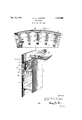
A preferred embodiment of the invention is illustrated in the drawings, inwhichy- Fig. 1 is a fragmentary plan, partly in section.
Fig. 2 is a perspective showing the parts sectioned on the line 2 2 of Fig. 1.
In thedrawings a cylindrical gas holder shell is shown, but shells of polygonal form are in common use and the invention may be adapted to such shells by obvious modifications.
The vertical wall or shell Vof the holder is indicated generally by the numeral 6. The
piston consists of a flat plate structure 7 andl a depending peripheral skirt 8 materially smaller in diameter than the shell 6, and a peripheral trough which encircles the lower portion of the skirt 8 and which is made up of a bottom 9 and a side wall 11. This confines a bath 12 of liquid lubricant such as oil, tar, etc.
Dipping into the bath 12 is an annular metal skirt 13 which is riveted to one flange of a channel-shaped scraper member 14. The other flange seats against the shell 6 and serves to remove ice or other obstructions therefrom. Extending upward from the channel member 14 are a plurality of spaced brackets 15, which at their upper ends are Y riveted to a reversely arranged channelshaped scraper 16.
Confined between the scrapers 14 and 16 are a plurality of annular strips 17 of absorbent packing material, such as felt.V
These annuli can not be made continuous in holders of ordinary size, but the joints in successive strips are staggered relatively toeach relatively to the member 15.
other to prevent leakage. VThe group of strips 17 is backed upby a flexible' annulus 18 of sheet metal, towhich are attached' a plurality of angle' brackets 19; There is one bracket 19 foreach member 15 and the two arespaced. apart and bidged by Pin 21 the Y engagement being loose so that the pin can cant when lthe member 19 moves outward `Each pin 21"is engaged bya corresponding lever 22. These levers `arepivoted at 23 on' brackets 24 and are loaded by weights 25, or any equivalent-means. In this way'the levers `support the entire packing and scraper` structure-and `develop a force reaction between the member 19 and 15. which urges the packing elements 17 and 18 outward relatively to the scrapers 14 and 16. It will be observed that the packing structure while closely confined by the scraper structure is mechanically independent thereof.
It will be observed that the lubricant bath is subject, outside the skirt 13, to the gas pressure in the holder, and hence rises to a high elevation within that skirt. This makes it possible to lubricate the packing strips 17 through ports 26 formed in the annulus 18.
The embodiment shown in the drawings is intended to be illustrative rather than limit-V ing, and possible modifications are contemplated.
What is claimed is,-l
1. Inl a waterless gas holder the combination of ashell; a piston movable vertically therein to vary the effective volume of the holder; a liquid retaining trough encircling the piston; asubstantially rigid scraper structure encircling the piston and including two spaced annular scraping elements in contact with the shell, the lower scraping element having means to form a dip seal with the liquid in said trough; absorbent sealing elements confined between said scraper elements; and means for supporting the scraper elements on the piston and for exerting yielding pressure on the sealing elements.
. 2. In a waterless gas holder, the combinaf Uyl tot
tion of a shell; Va piston movable vertically holder; a liquid retaining trough encircling the piston; a substantially rigid scraper structure encircling the piston and including two spaced annular scraping element-s in contact with the shell, the lower scraping element having means kto form a dip seal with the liqulird :said trough; an absorbent sealing medium confined between said scraper elements; and means comprising a plurality of loaded levers for supporting sai-d scraper structure and for 'developing -atorce reaction between the scraper structure and the sealing medium to force the latter into sealing engagement with the shell.
3. In a waterless gas holder, the combination :erf a shell; a pist-on movable vertically therein to vary lthe effective volume of the helder; -a Ascraper structure encircling the piston and including two vertically spaced annulgar scraping elements; a packing element mounted between said scraping .elements; and means compris-ing a plurality of loaded levers arranged to support said scraper structure and to develop between the latter and the packing element Aa force' reaction which urges the packing element into sea-ling contact with the .shell In testimony 'whereof I have signed my name to this specification.
JOHN R. L. SANTOS.
Priority Applications (1)
| Application Number | Priority Date | Filing Date | Title |
|---|---|---|---|
| US302785A US1836282A (en) | 1928-08-29 | 1928-08-29 | Gas holder |
Applications Claiming Priority (1)
| Application Number | Priority Date | Filing Date | Title |
|---|---|---|---|
| US302785A US1836282A (en) | 1928-08-29 | 1928-08-29 | Gas holder |
Publications (1)
| Publication Number | Publication Date |
|---|---|
| US1836282A true US1836282A (en) | 1931-12-15 |
Family
ID=23169196
Family Applications (1)
| Application Number | Title | Priority Date | Filing Date |
|---|---|---|---|
| US302785A Expired - Lifetime US1836282A (en) | 1928-08-29 | 1928-08-29 | Gas holder |
Country Status (1)
| Country | Link |
|---|---|
| US (1) | US1836282A (en) |
-
1928
- 1928-08-29 US US302785A patent/US1836282A/en not_active Expired - Lifetime
Similar Documents
| Publication | Publication Date | Title |
|---|---|---|
| SU506312A3 (en) | Device for sealing the mouth of oil wells | |
| US2897998A (en) | Floating roof seal arrangement | |
| US1836282A (en) | Gas holder | |
| US2028968A (en) | Lining for vessels | |
| US1870316A (en) | Gas holder | |
| US2846110A (en) | Wear plate for floating roof tank | |
| US1836283A (en) | Gas holder | |
| US1693468A (en) | Sealing piston for reservoirs for the storage of gas, steam, or easilyevaporating liquids | |
| US2080568A (en) | Floating roof construction | |
| US1825185A (en) | Packing for pistons and the like | |
| US4341323A (en) | Seal for floating roof tanks | |
| US1865969A (en) | Sealing means for fluid storing containers | |
| US1865792A (en) | Gas holder | |
| US1651131A (en) | Packing | |
| US1901874A (en) | Floating roof and sealing means therefor | |
| US2287212A (en) | Seals for floating roofs | |
| US2737310A (en) | Floating roof | |
| US1782949A (en) | Gas holder | |
| US1861860A (en) | Hanger for floating roofs | |
| US2260021A (en) | Sealing means for gas holder pistons | |
| US2408539A (en) | Fluid storage apparatus | |
| US2050405A (en) | Gas and liquid storage device | |
| RU2065391C1 (en) | Closure for floating cover of liquid storage reservoir | |
| US1366318A (en) | Air-spring | |
| NO131471B (en) |