US1817841A - Separable fastener - Google Patents
Separable fastener Download PDFInfo
- Publication number
- US1817841A US1817841A US396180A US39618029A US1817841A US 1817841 A US1817841 A US 1817841A US 396180 A US396180 A US 396180A US 39618029 A US39618029 A US 39618029A US 1817841 A US1817841 A US 1817841A
- Authority
- US
- United States
- Prior art keywords
- members
- projection
- series
- recess
- sided
- Prior art date
- Legal status (The legal status is an assumption and is not a legal conclusion. Google has not performed a legal analysis and makes no representation as to the accuracy of the status listed.)
- Expired - Lifetime
Links
- 230000004048 modification Effects 0.000 description 3
- 238000012986 modification Methods 0.000 description 3
- 231100000706 no observed effect level Toxicity 0.000 description 2
- 241000282320 Panthera leo Species 0.000 description 1
- 230000000694 effects Effects 0.000 description 1
Images
Classifications
-
- A—HUMAN NECESSITIES
- A44—HABERDASHERY; JEWELLERY
- A44B—BUTTONS, PINS, BUCKLES, SLIDE FASTENERS, OR THE LIKE
- A44B19/00—Slide fasteners
- A44B19/02—Slide fasteners with a series of separate interlocking members secured to each stringer tape
- A44B19/04—Stringers arranged edge-to-edge when fastened, e.g. abutting stringers
- A44B19/06—Stringers arranged edge-to-edge when fastened, e.g. abutting stringers with substantially rectangular members having interlocking projections and pieces
-
- Y—GENERAL TAGGING OF NEW TECHNOLOGICAL DEVELOPMENTS; GENERAL TAGGING OF CROSS-SECTIONAL TECHNOLOGIES SPANNING OVER SEVERAL SECTIONS OF THE IPC; TECHNICAL SUBJECTS COVERED BY FORMER USPC CROSS-REFERENCE ART COLLECTIONS [XRACs] AND DIGESTS
- Y10—TECHNICAL SUBJECTS COVERED BY FORMER USPC
- Y10T—TECHNICAL SUBJECTS COVERED BY FORMER US CLASSIFICATION
- Y10T24/00—Buckles, buttons, clasps, etc.
- Y10T24/25—Zipper or required component thereof
- Y10T24/2539—Interlocking surface constructed from plural elements in series
- Y10T24/255—Interlocking surface constructed from plural elements in series having interlocking portion with specific shape
- Y10T24/2554—Interlocking surface constructed from plural elements in series having interlocking portion with specific shape including complementary formations on opposite walls for engaging mating elements
Definitions
- Separable fasteners of the type brought into interlocking engagement by swinging the fasteners successively into place are usually insecure if the opposing series are flexed out of the plane of the stringers to which they are attached.
- the present invention is designed to obviate this by limiting the swinging movement of the fastening members relatively to each other.
- FIG. 1 shows an elevation of the fastener.
- Fig. 2 a plan view of one of the fastening members
- Fig. 4 a sectional view taken on the line 4-4 in Fig. 2.
- Fig. 5 a plan view of the reverse side of the member shown in Fig. 2.
- Fig. 6 a reverse side of the member shown in Fig. 3.
- Fig. 7 a plan view of an alternative con-.
- Fig. 8 a plan view of a further modification.
- Fig. 9 a plan view of a modification.
- Fig. 10 an edge elevation of the structure shown in Fig. 9.
- the member 2 has jaws 4 with inturned ends 5 for clamping the ribs along the edges ofthe stringers.
- Each member 2 has a threesided projection 6 on one face of the mem- 5 her. This projection has the inclined side This walls 7, one of the walls 8 being adjacent and parallel to the free end of the member, the other converging side walls meeting at 9 at a point remote from the free end of the member.
- the reverse side ofeach member v has a recess 10 similar in shape and adapted to receive the projections, but with the sides 11 reversed, or out of register with the projection on the opposite face of the same member.
- the side 12 of the recess parallel to the free end of the member is remote from said end, whereas the apex of' the triangle is at 13 adjacent to the free end.
- Fig. 8. a somewhat similar structure is shown, the member 20 having clamping jaws s5 21 and V-shaped projections 22 with the apex remote from the free end of the member.
- Figs. 9 and 10 a modification is shown in which the member 23 has clamping jaws 90 24 and the members are provided with the three-sided projections 25 with three-sided recesses 26 behind the three-sided projections. It will be noted that the recesses and projections are similarly arranged on both 95 faces of each member so that there is adouble locking effect and the. devices are" interchangeable.
- a separable fastener comprising oppos- 10c ing series of interlocking members adapted to swin into interlocking position, each member aving a three-sided projection and a three-sided recess adapted to receive a similar rojection of an opposing series the three si e walls of the projection confronting the three side walls of the recess receiving the projection, said members of the opposing series having their projections and recesses arranged in the same relation to the free ends of the members, the members of both series being interchangeable.
- a separable fastener comprising opposing series of interlocking members adapted. to swing into interlocking position, each member having a three-sided projection on one face of the member and a three-sided recess on the reverse face of the member, the walls of said recess and projection being in reverse relation and the recesses of one series being adapted to receive the projections of the other series, the three side walls of the projection confronting thethree side .Walls of the recess receiving the projection.
- a separable fastener comprising opposing series of interlocking members adapted to swing into interlocking position, each memberhaving a three-sided projection on one face of the member and a three-sided recess son the reverse face of the member, one side only of the projection being parallel with aside of the recess, said parallel sides of the projection and recess being parallel to the free end of the member and the recesses of one series being adapted to re ceive the projections of the other series, the sides of the projections and the recesses of the members of both series having the same relation to the ends of the members, the
- a separable fastener comprising opposing series of interlocking members adapted to swing into interlocking position, each member havingv a three-sided pro'ection on one face of the member and a t ree-sided recess on the reverse side of the member,
- one side only of the projection being parallel with a side of the recess, the parallel side of the projection being adjacent to the free end of the member and the recesses of one series being adapted to receive the projecmy hand.
Landscapes
- Slide Fasteners, Snap Fasteners, And Hook Fasteners (AREA)
Description
-Au .4,19s1. ,PQ X 1,817,841
SEPARABLE FASTENER Filed Sept. 50, 1929 INVENTOR.
F/6.8. fiat 7.
ATTORNEYS. I
Patented Aug. 4, 1931 UNITED STATES PATENT OFFICE NOEL J. POUX, F MEADVILLE, PENNSYLVANIA, ASSIGNOR T0 LION FASTENER ING, OF.MEADVILLE, PENNSYLVANIA, A CORPORATION OF DELAWARE SEPARABLE FASTENER Application filed September 30, 1929. Serial No. 396,180.
Separable fasteners of the type brought into interlocking engagement by swinging the fasteners successively into place are usually insecure if the opposing series are flexed out of the plane of the stringers to which they are attached. The present invention is designed to obviate this by limiting the swinging movement of the fastening members relatively to each other.
limiting of'the fiexure may be accomplished by forming the interlocking projections and recesses with three sides as distinguished from a greater number of sides which more nearly approach the round, or non-locking structure. It is also desirable to form the members of a separable fastener so that all the members will be interchangeable and with the present invention this is accomplished. Features and details of the invention will appear from the specification and claims.
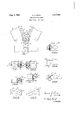
A. preferred embodiment of the invention is illustrated in the accompanying drawings as follows Fig. 1 shows an elevation of the fastener.
Fig. 2 a plan view of one of the fastening members;
3 an opposing fastening member.
Fig. 4 a sectional view taken on the line 4-4 in Fig. 2.
Fig. 5 a plan view of the reverse side of the member shown in Fig. 2.
Fig. 6 a reverse side of the member shown in Fig. 3. Fig. 7 a plan view of an alternative con-.
struction.
Fig. 8 a plan view of a further modification.
Fig. 9 a plan view of a modification. Fig. 10 an edge elevation of the structure shown in Fig. 9.
1 marks the stringers, 1a. ribs along the edges of the stringers, 2 interlocking members, and 3 the slider for closing and separating the members. v
The member 2 has jaws 4 with inturned ends 5 for clamping the ribs along the edges ofthe stringers. Each member 2 has a threesided projection 6 on one face of the mem- 5 her. This projection has the inclined side This walls 7, one of the walls 8 being adjacent and parallel to the free end of the member, the other converging side walls meeting at 9 at a point remote from the free end of the member. The reverse side ofeach member v has a recess 10 similar in shape and adapted to receive the projections, but with the sides 11 reversed, or out of register with the projection on the opposite face of the same member. Thus the side 12 of the recess parallel to the free end of the member is remote from said end, whereas the apex of' the triangle is at 13 adjacent to the free end. In this way it is possible to form the members of exactly the same shape so that they may all be interchangeable and applicable to either series. It will be noted that the projection 6 in either one, as viewed in Figs. 2 and.3 will nest in a recess of the opposing series of members, said recesses being indicated in dotted lines. In this way it is possible to obtain the advantages of the three-sided structure which more securely locks the members against fiexure out of the plane of the stringers and at the same time forms all the members alike.
Themodification shown in F 7 has the interlocking member 17 with jaws l8 and the three-sided interlocking member has one side indented giving a completed V-shaped projection 19 with the apex adjacent to the free end of the member. The recesses jnet. shown) are, of course, reversed.
Fig. 8. a somewhat similar structure is shown, the member 20 having clamping jaws s5 21 and V-shaped projections 22 with the apex remote from the free end of the member.
In Figs. 9 and 10 a modification is shown in which the member 23 has clamping jaws 90 24 and the members are provided with the three-sided projections 25 with three-sided recesses 26 behind the three-sided projections. It will be noted that the recesses and projections are similarly arranged on both 95 faces of each member so that there is adouble locking effect and the. devices are" interchangeable.
What I claim as new is 1. A separable fastener comprising oppos- 10c ing series of interlocking members adapted to swin into interlocking position, each member aving a three-sided projection and a three-sided recess adapted to receive a similar rojection of an opposing series the three si e walls of the projection confronting the three side walls of the recess receiving the projection, said members of the opposing series having their projections and recesses arranged in the same relation to the free ends of the members, the members of both series being interchangeable.
2. A separable fastener comprising opposing series of interlocking members adapted. to swing into interlocking position, each member having a three-sided projection on one face of the member and a three-sided recess on the reverse face of the member, the walls of said recess and projection being in reverse relation and the recesses of one series being adapted to receive the projections of the other series, the three side walls of the projection confronting thethree side .Walls of the recess receiving the projection.
3. A separable fastener comprising opposing series of interlocking members adapted to swing into interlocking position, each memberhaving a three-sided projection on one face of the member and a three-sided recess son the reverse face of the member, one side only of the projection being parallel with aside of the recess, said parallel sides of the projection and recess being parallel to the free end of the member and the recesses of one series being adapted to re ceive the projections of the other series, the sides of the projections and the recesses of the members of both series having the same relation to the ends of the members, the
niembers of both series being interchange= able and the three side walls of the projec-v tion of each member confronting the three side walls of the recess receiving the projection.
4. A separable fastener comprising opposing series of interlocking members adapted to swing into interlocking position, each member havingv a three-sided pro'ection on one face of the member and a t ree-sided recess on the reverse side of the member,
one side only of the projection being parallel with a side of the recess, the parallel side of the projection being adjacent to the free end of the member and the recesses of one series being adapted to receive the projecmy hand.
t NOEL J. POUX.
Priority Applications (1)
| Application Number | Priority Date | Filing Date | Title |
|---|---|---|---|
| US396180A US1817841A (en) | 1929-09-30 | 1929-09-30 | Separable fastener |
Applications Claiming Priority (1)
| Application Number | Priority Date | Filing Date | Title |
|---|---|---|---|
| US396180A US1817841A (en) | 1929-09-30 | 1929-09-30 | Separable fastener |
Publications (1)
| Publication Number | Publication Date |
|---|---|
| US1817841A true US1817841A (en) | 1931-08-04 |
Family
ID=23566187
Family Applications (1)
| Application Number | Title | Priority Date | Filing Date |
|---|---|---|---|
| US396180A Expired - Lifetime US1817841A (en) | 1929-09-30 | 1929-09-30 | Separable fastener |
Country Status (1)
| Country | Link |
|---|---|
| US (1) | US1817841A (en) |
Cited By (2)
| Publication number | Priority date | Publication date | Assignee | Title |
|---|---|---|---|---|
| US2497122A (en) * | 1945-10-01 | 1950-02-14 | North & Judd Mfg Co | Slide fastener scoops or interlocking elements |
| DE1144215B (en) * | 1954-07-16 | 1963-02-28 | Dugald Laird Hair | Zipper with concealed fasteners |
-
1929
- 1929-09-30 US US396180A patent/US1817841A/en not_active Expired - Lifetime
Cited By (2)
| Publication number | Priority date | Publication date | Assignee | Title |
|---|---|---|---|---|
| US2497122A (en) * | 1945-10-01 | 1950-02-14 | North & Judd Mfg Co | Slide fastener scoops or interlocking elements |
| DE1144215B (en) * | 1954-07-16 | 1963-02-28 | Dugald Laird Hair | Zipper with concealed fasteners |
Similar Documents
| Publication | Publication Date | Title |
|---|---|---|
| US2355996A (en) | Offset double-acting scoop | |
| US1817841A (en) | Separable fastener | |
| US1923262A (en) | Fastening device | |
| US2300369A (en) | Separable slide fastener | |
| US2095270A (en) | Slider for covered separable fasteners | |
| US2347428A (en) | Mortise joint separable fastener | |
| US1817840A (en) | Separable fastener | |
| US3577609A (en) | Hook and eye type fastener | |
| US2784473A (en) | One-stringer separable fastener | |
| US2392338A (en) | Slide fastener | |
| US2879573A (en) | Slide fasteners | |
| US1803106A (en) | Flexible closure | |
| US2168598A (en) | Separable fastener | |
| US2876519A (en) | Fastener | |
| US2455178A (en) | Winglock slider for slide fasteners | |
| US1864614A (en) | Separable fastener | |
| US2322537A (en) | Separable fastener | |
| US1659480A (en) | Fastener | |
| US2160879A (en) | Slider | |
| US1906808A (en) | Separable fastener | |
| US1817839A (en) | Separable fastener | |
| US2342418A (en) | End stop for separable fasteners | |
| US1809717A (en) | Fastening device | |
| US3068541A (en) | One-sided separable fastener | |
| US1746237A (en) | Separable fastener |