US1817085A - Tractor plow - Google Patents
Tractor plow Download PDFInfo
- Publication number
- US1817085A US1817085A US366814A US36681429A US1817085A US 1817085 A US1817085 A US 1817085A US 366814 A US366814 A US 366814A US 36681429 A US36681429 A US 36681429A US 1817085 A US1817085 A US 1817085A
- Authority
- US
- United States
- Prior art keywords
- tractor
- frame
- plow
- axle structure
- wheels
- Prior art date
- Legal status (The legal status is an assumption and is not a legal conclusion. Google has not performed a legal analysis and makes no representation as to the accuracy of the status listed.)
- Expired - Lifetime
Links
Images


Classifications
-
- A—HUMAN NECESSITIES
- A01—AGRICULTURE; FORESTRY; ANIMAL HUSBANDRY; HUNTING; TRAPPING; FISHING
- A01B—SOIL WORKING IN AGRICULTURE OR FORESTRY; PARTS, DETAILS, OR ACCESSORIES OF AGRICULTURAL MACHINES OR IMPLEMENTS, IN GENERAL
- A01B59/00—Devices specially adapted for connection between animals or tractors and agricultural machines or implements
- A01B59/04—Devices specially adapted for connection between animals or tractors and agricultural machines or implements for machines pulled or pushed by a tractor
- A01B59/041—Devices specially adapted for connection between animals or tractors and agricultural machines or implements for machines pulled or pushed by a tractor preventing or limiting side-play of implements
-
- A—HUMAN NECESSITIES
- A01—AGRICULTURE; FORESTRY; ANIMAL HUSBANDRY; HUNTING; TRAPPING; FISHING
- A01B—SOIL WORKING IN AGRICULTURE OR FORESTRY; PARTS, DETAILS, OR ACCESSORIES OF AGRICULTURAL MACHINES OR IMPLEMENTS, IN GENERAL
- A01B63/00—Lifting or adjusting devices or arrangements for agricultural machines or implements
- A01B63/02—Lifting or adjusting devices or arrangements for agricultural machines or implements for implements mounted on tractors
- A01B63/06—Lifting or adjusting devices or arrangements for agricultural machines or implements for implements mounted on tractors operated mechanically by tractor motor
Definitions
- the main objects of the invention are to provide a plow attachment for tractors which, when connected, will turn with the tractor as a unit; will serve to position the plows close to the rear axle structure of the tractor and, will provide for free floating movement of the attachment vertically with res set to the tractor during operation.
- t is also an object of the invention to provide a form of flexible draft connection or linkage between the attachment and the tractor that will hold the attachment rigidly in position with respect to the tractor as regards horizontal angularmovements, while permitting the attachment and the plows carried thereby to independently follow undulations in ground surfaces.
- the purpose of the invention is to provide a two-way plow attachment having the characteristics above outlined and which will be particularly adapted for a standard type of wide tread or row crop tractor and designed to be mounted between the widely spaced rear wheels of that tractor with the frame of the attachment occupying most of the space between the wheels and practically all located within the transverse planes enclosing the wheels.
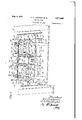
- Figure 1 is a plan view showing the plow of the invention in position on the rear end of a tractor
- Figure 2 is a side elevation of the structure shown 1n Figure 1 with the tractor wheel omitted;
- Figure 3 is a rear elevation of the structure shown in Figure 1 with the plow beams sectioned on the line 3:3 of Figure 1;
- Figure .4 is a transverse vertical section 928- eri l N- 36 .81%-
- Figure 5 is a longitudinal section through said mechanism on the line 5-5 of Figure 4;
- Figure 6 is a detail view of the intermittently rotated member in the clutch mechanism embodied in the structure of Figures 4 and 5;
- Figure 7 is a View of the same part as shown in Figure 6 viewed at right angles.
- the plow attachment is illustrated as connected to a tractor having a transversely extended rear axle structure comprising a horizontal axle housing 10 having depending vertical housings 11 fixed to each end thereof.
- Traction wheels 12 are mounted on the outer sides of the depending housings 11 and are driven through differential shafts and gearing contained within the housings 10 and 11.
- the above construction provides an upwardly arched axle structure having widely spaced rear wheels supporting the same.
- the tractor also comprises a comparatively narrow, forwardly extending, central body portion 1a which supports the power plant (not shown) and which preferably comprises side bars or sills 15.
- a transmission housing 17 which is extended below the level of the sills as a second housing 18, in which there is enclosed gearing for driving, from the transmission, a rearwardly directed power take-off shaft 19.
- the location of the power take-off shaft is accordingly central and below the level of the transverse portion of the axle structure.
- the plow attachment designed for connection to an d cooperation with a tractor having the rear end structure above set forth comprises a substantially upright frame structure composed of an oblong, rectangular frame 20 with its inner diameter extending parallel to the axle structure of the tractor and occupying substantially all of the space between the depending housings 11.
- the frame 20 is of open construction and prefervertical bars 27, which below the sill members.
- the framestructure also includes vertical side members 21 which are centrally secured to the ends of therectangularframe 20.
- the side members 21 extend upwardly above the transverse portion of the axle structure and downwardly below frame 20 and at their low er ends carry bearing bores 22 ( Figure 3) for a transverse axle 23 on which there is journaled a pair of ground wheels 24.
- Links or braces 26 connect the upper ends of the upright members 21 with the upper portions of the end sections of frame 20.
- the sill members 15 clamped to the sills and extend above and Each of these bars is connected to each of the vertical members 21 of the attachment frame by means of a pair of vertically spaced, parallel links 29, 30.
- Eachpair of'links is arranged with one link passing above and the other'below the axle structure ( Figure 2), and the respective links of each pair arepivote'd to one upright bar 27 and to an upright member 21 of the frame 20.
- This arrangement providcsflexible draft connections for the attachment frame, which is thus 'held upright and rigid as against horizontal, angular movement, while being per-- mitt'ed free floating' movement in a vertical direction on rectilinear lines.
- the fact that thecoupling links 29 and 30 at either side diverge rearwardly from their pointsof connection to the upright bars 27 to their connections tothe members 21 addsto theresistance to horizontal angular movement of the attachment frame. 1
- the attachment frame structure above'described isparticularly adapted for support.
- each plow unit comprises a beam structure 35, which may be composed of multiple bars, as illustrated in Figure 1, diverging at therearto afford properly spaced supports for the plow beams or standards 36 carrying theplow bodies 37.
- the members constituting the beam structure 1 preferably include a rearwardly extendingv brace member'38 and at their forward ends one'of the members forming the forward portion of the beam. structure ure "1) to providea forked forward end on the 'beam structure.
- Each plowing unit-and have secured thereto bars are centrally.
- Fig-V beam structure 35 is intermediately supported on the frame in a manner permitting it to be raised and lowered with respect thereto.
- the preferred structure for so supporting the plowing units comprises rearwardly extending bail members'lO, each of which has an outer arm pivoted at 41 to the end piece of frame 20 at the point where end members 21 are secured to frame 20, and an inner arm pivotedat 42 to one ofthearms of a forward-' ly and downwardly extending Ll-shaped section 43 forming the central section of frame 20;
- This U-shap'ed section is rigidly secured centrally of frame 20, as shown in Figure 1 with its arms extending downwardly and supported onaxle 23. 7
- each bail member 40 has pivotally suspended thereon second bailshaped members d'fon which are mounted sleeves 45 to which the beam structures 35 are intermediately clampech Asthe attachment frame is located close behindthe axle structure, the forward ends of thebeam'struo tures 35are positioned under and a little for wardof the axle structure, as seen in Figure 2, the forward forked ends of the beams being bent downwardly to afford a low point of draft connection.
- the transverse portion' l8 of'the drawbar carries clevises 49 to each of which there is pivotally, connected a draft link 50, which is in turn pivotally connected at 51 to the forward end of one fork or member of the plow beam structure.
- each draft link 50 is connected shown in dotted lines on Figure 1, at 51 with the offset member 39 at the front endof the beam structure.
- the link 5l is preferably composed of two members having a turnbuckle connec'tion'as illustrat ed.
- the construction specified affords a vertically flexible. draft connection between each beam and a forward point below. the bodyof the tractor giving the advantage of a low point of draft connection.
- each bail 40 is connected to crankmechanism mounted on the upper transverse member of the frame 20.
- the crank mechanism comprises a.rock shaft .55 journaled in suitablelbearings' on the frame 20 and having oppositely directed crank arms-55 and the crank arm is forwardly directed and is formed to carry a slide block 58 whichis adjustable longitudinally on the arm 57.
- the adjusting mechanism for the slide 58 consists of a screw shaft 59 journaled in a bearing 60 on the shaft 5 and having a crank handle 61 at its uppe end.v A screwthreaded opening in a lug 6 on the slide block 58 receives the screw threaded end of the screw shaft 59. Turning movements of the shaft 59 will, therefore, move the block 58 on the arm 57.
- the block 58 is pivotally connected by a link 63 with the bail 40, and, as the link will be moved with the block 58 during adjustment thereof, a. fixed adjustment of bail and the plowing unit carried thereby may be readily effected to vary the depth of plowing.
- This unit consists For Y of a casing 65, which is supported on rear wardly extending, spaced bars 66 which are clamped or bolted to the sides of the casing at their rear ends and are secured to the arms of the central U-shaped frame member 43 at their front ends.
- Tie bars 6'? connect the bars 66 with the upper portion of the frame member l3 forming a rigid supporting structure for the housing 65. ft will be seen that the housing is thus located centrally on the frame 20 and substantially in alignment with the power take-off shaft 19.
- the casing 65 is a closed structure for the retention of lubricant and is formed with bearings for a longitudinally extending worm shaft 70 (Figure 5), the forward end of which projects from the casing and is connected to the poW- er take-off shaft 19 through an extensible and flexible drive shaft 71 formed of telescopically related sections connected to the power take-off shaft and tot-he wormshaft by universal joints as illustrated.
- the casing 5 is also provided with bearings for a transverse shaft 752, which extends slightly beyond the casing at either side. ⁇ Vithin the casing.
- each driven clutch member has an oppositely notched disk portion 80 fixed on sleeve 77 and positioned adjacent one side and over an open face of the worm wheel '73.
- the disk portion 80 on the side away from the worm wheel has pivoted to it at 81 a trip member 82 formed with opposite arms terminating at the notches in the disk 8 as trip dogs 83.
- the trip member 82 carries a clutch roller (a l which extends through a slot 85 in the disk member 80 and into the hollow space within one side of the worm wheel 73 and ciacent the notched inner surface of the "range T l.
- A. coil spring 85 normally urges u re roller 84 into engagement with the notched surface "5. It will be understood that the clutch elements are duplicated on each end of the shaft 72, but are independent as to actuation.
- the control means for the trip dogs 83 consists of a. trip lever 86 for each clutch mechanism. lhese levers extend upwardly from the upper portion of the casing in convenient position to be reached from the operators station on the tractor. Each leverhas an inwardly bent portion 87 (Fig ure 4:).
- a spring 90 ( Figure 2) connects the lever and casing and acts to swing the lever in a direction to urge the trip roller into the notches of the disk 80, thereby nor mally swinging the trip member 82 against the tension of spring 85 and loci-ring the clutch in released or disconnected position.
- crank pins 79 of each intermittently operable clutch element are connected by link rods 91 to the crank arms 56 of the rockshafts 55.
- the crank elements 78 of the clutches are so related to the actuating mechanism as to be in substantially dead center relation with the links 91 when disconnected from the drive after each half revolution.
- the structure above described accordingly exemplifies a tractor plow organization in which there is-afforded a close coupled plow carrying frame flexibly connected 'to the tractor and supported on carrying Wheels which bearthe entire weight of the attach ment, thereby permitting the plow carrying frame to float or move vertically with respect to the tractor so that the plows follow the contour of the ground without being afieoted by up and down'movements of the tractor.
- the construction also presents a novel mannor of mounting and adjusting plowing units wheels 7 and on the frame and of'connecting same to the tractor by draft elements located below the level of the tractor body and "forwardly of its axle structure;
- a tractor plow comprising a substantially upright frame, a pair of ground wheels on the frame constituting the sole support therefor, a rearwardly extending bail having its arms pivoted to the frame, a plow having a beam intermediately fulcrumed on the bail, adjusting mechanism carried by the frame and connected to the bail, and means on the frame adapted to connect the frame to a tractor in floating relation thereto.
- a tractor plow comprising a frame, a pair of ground wheels on the frame constituting the sole support thereof, a rearwardly extending bail having its arms pivoted to the frame, a second bail pivotally suspended from the cross member of the first bail, a plow having a beam intermediately mounted on the second bail, adjusting mechanism carried by the frame and connected to the first bail, and means on the frame adapted to connect the frame to a tractor in floating relation thereto.
- a tractor plow comprising a substantially upright laterally extended frame, a pair of ground wheels on the frame constituting the sole support thereof, a rearwarr ly extending bail on each lateral portion of the frame each bail having its arms pivoted to the frame, a plow beam intermediately fulcrumed on each bail said beams carrying opposite plows, means on the frame forselectively lifting and lowering either bail and plow, and means on the frame adapted to connect the frame to a tractor in floating relation thereto.
- a tractor comprising rear wheels, an axle structure connee-ting said wheels and a power take-off shaft extending at right angles to the axle structure, of a wheel supported frame, means for connecting the frame to the tractor in floating relation thereto, a plow having a beam connected to the tractor, vertically adjustable supporting means connecting the beam to the frame crank actuated mechanism on the frame for lifting and lowering the supporting means, a flexible drive shaft.
- the combination with a tractor comprising rear wheels, an axle structure connecting the wheels and a centrally positioned.
- power takeoff shaft extending at right angles to the axle andlocated below thesame, of a two-way plow comprising a wheel supported frame positioned in close relation to the rear side of the axlestructure, draft links connecting the frame tov the tractor in vertically floating relation, opposite plows having beams intermediately fulcrumed on the frame at each side of the central longitudinal line of the tractor and connected to the tractor, tripactuated intermittent clutch mechanism carried by the frame between the plows, lifting and lowering mechanismconnecting said mechanism with each plow beam, and aflexible drive shaft connecting the power take-off shaft with the clutch mechanism.
- a tractor comprising rear wheels, an axle structure connecting the wheels and a centrally positioned power take-off shaft extend at right angles to the axle and located below the same, of a two-way plow comprising a wheel supported frame positioned in close relation to the rear side of the axle structure, draft links connecting the frame to the tractor in vertically floating relation, opposite plows having beams intermediately fulcrumed on the frame at each side of the central longitudinal line of the tractor and connected to the tractor, a pair of intermittent clutch mechanisms carried by the frame between the plows, a common driving element engageable with either clutch mechanism, trip members for controlling the actuation of each clutch, lifting and lowering connections connecting the respective plows and clutches, and a flexible shaft connecting the power take-off shat with the common driving element for the clutches.
Landscapes
- Life Sciences & Earth Sciences (AREA)
- Engineering & Computer Science (AREA)
- Mechanical Engineering (AREA)
- Soil Sciences (AREA)
- Environmental Sciences (AREA)
- Zoology (AREA)
- Agricultural Machines (AREA)
- Soil Working Implements (AREA)
- Handcart (AREA)
Priority Applications (3)
| Application Number | Priority Date | Filing Date | Title |
|---|---|---|---|
| US366814A US1817085A (en) | 1929-05-29 | 1929-05-29 | Tractor plow |
| GB22368/29A GB336943A (en) | 1929-05-29 | 1929-07-20 | Improvements in tractor plows |
| DEI38756D DE534751C (de) | 1929-05-29 | 1929-07-23 | Anhaengepflug fuer Zugmaschinen |
Applications Claiming Priority (1)
| Application Number | Priority Date | Filing Date | Title |
|---|---|---|---|
| US366814A US1817085A (en) | 1929-05-29 | 1929-05-29 | Tractor plow |
Publications (1)
| Publication Number | Publication Date |
|---|---|
| US1817085A true US1817085A (en) | 1931-08-04 |
Family
ID=23444642
Family Applications (1)
| Application Number | Title | Priority Date | Filing Date |
|---|---|---|---|
| US366814A Expired - Lifetime US1817085A (en) | 1929-05-29 | 1929-05-29 | Tractor plow |
Country Status (3)
| Country | Link |
|---|---|
| US (1) | US1817085A (de) |
| DE (1) | DE534751C (de) |
| GB (1) | GB336943A (de) |
Cited By (5)
| Publication number | Priority date | Publication date | Assignee | Title |
|---|---|---|---|---|
| US2469996A (en) * | 1944-11-08 | 1949-05-10 | Deere & Co | Tractor mounted plow and gauge wheel |
| US2567736A (en) * | 1945-02-16 | 1951-09-11 | Deere & Co | Quicly attachable implement |
| US2575527A (en) * | 1944-08-02 | 1951-11-20 | Deere & Co | Two-way plow |
| US2619016A (en) * | 1947-12-15 | 1952-11-25 | James E Dooley | Two-way plow |
| US2676525A (en) * | 1949-08-15 | 1954-04-27 | Deere & Co | Power lift mechanism for two-way plows |
-
1929
- 1929-05-29 US US366814A patent/US1817085A/en not_active Expired - Lifetime
- 1929-07-20 GB GB22368/29A patent/GB336943A/en not_active Expired
- 1929-07-23 DE DEI38756D patent/DE534751C/de not_active Expired
Cited By (5)
| Publication number | Priority date | Publication date | Assignee | Title |
|---|---|---|---|---|
| US2575527A (en) * | 1944-08-02 | 1951-11-20 | Deere & Co | Two-way plow |
| US2469996A (en) * | 1944-11-08 | 1949-05-10 | Deere & Co | Tractor mounted plow and gauge wheel |
| US2567736A (en) * | 1945-02-16 | 1951-09-11 | Deere & Co | Quicly attachable implement |
| US2619016A (en) * | 1947-12-15 | 1952-11-25 | James E Dooley | Two-way plow |
| US2676525A (en) * | 1949-08-15 | 1954-04-27 | Deere & Co | Power lift mechanism for two-way plows |
Also Published As
| Publication number | Publication date |
|---|---|
| GB336943A (en) | 1930-10-20 |
| DE534751C (de) | 1931-10-03 |
Similar Documents
| Publication | Publication Date | Title |
|---|---|---|
| US3777823A (en) | Agricultural impelement trailers | |
| US1637811A (en) | Agricultural implement | |
| US3193023A (en) | Disc harrow | |
| US3305025A (en) | Two-way moldboard plow | |
| US1817085A (en) | Tractor plow | |
| US2437879A (en) | Two-way plow | |
| US2919754A (en) | Tractor implement connection | |
| US1831997A (en) | Plow | |
| US2619016A (en) | Two-way plow | |
| US2505609A (en) | Direct-coupled automatic release tractor plow | |
| US2098472A (en) | Plow | |
| US2306814A (en) | Tractor plow | |
| US2769384A (en) | Plow | |
| US1885955A (en) | Agricultural implement | |
| USRE21989E (en) | Tractor dttlkmknt | |
| US3321029A (en) | Hydraulically controlled plow | |
| US2012458A (en) | Plow | |
| US2613491A (en) | Horizontally hinged wheeled disk harrow | |
| US1222299A (en) | Traction-plow. | |
| US2109677A (en) | Tractor implement | |
| US1902846A (en) | Plow attachment for tractors | |
| US2440782A (en) | Two-way plow | |
| US2127347A (en) | Cultivator plow | |
| US1960269A (en) | Implement attachment for tractors | |
| US1653677A (en) | Draft device |