US1815692A - Sound recording mechanism - Google Patents
Sound recording mechanism Download PDFInfo
- Publication number
- US1815692A US1815692A US91483A US9148326A US1815692A US 1815692 A US1815692 A US 1815692A US 91483 A US91483 A US 91483A US 9148326 A US9148326 A US 9148326A US 1815692 A US1815692 A US 1815692A
- Authority
- US
- United States
- Prior art keywords
- recording
- strip
- sound
- film
- support
- Prior art date
- Legal status (The legal status is an assumption and is not a legal conclusion. Google has not performed a legal analysis and makes no representation as to the accuracy of the status listed.)
- Expired - Lifetime
Links
Images

Classifications
-
- G—PHYSICS
- G11—INFORMATION STORAGE
- G11B—INFORMATION STORAGE BASED ON RELATIVE MOVEMENT BETWEEN RECORD CARRIER AND TRANSDUCER
- G11B3/00—Recording by mechanical cutting, deforming or pressing, e.g. of grooves or pits; Reproducing by mechanical sensing; Record carriers therefor
Definitions
- This invention relates to improvements in sound recording mechanism, and to a mechanism of this character more particularly adapted for use in recording sounds directly on standard motion picture strips in a cold state during the movement of the film strip through the mechanism.
- an objectof this invention is to provide a mechanism adapted :to efliciently record' sound on a standard motion picture Celluloid film strip in a cold state during the movement of the film strip through the mechanism, and which utilizes the small space between the opening for the sprocket teeth and the edge -of the picture surface of the film for the sound record groove.
- Another object of the invention is to provide a mechanism for recording the sound on a standard motion picture film strip in the cold state in which in the movement of the film through the mechanism the recording needle is operated in a uniform manner by the sound vibrations to be recorded in the strip and provided with suitable controlling mechanism to force the needle'nto the strip during the recording operation and prevent the same from scratching the film and being vibrated for recording undesirable vibrations of the mechanical structure of the recording mechanism.
- the invention further comprehends the efficient recording of sound on a standard motion picture film strip in al cold state by impressing the sound record in the strip with the provision of suitable means for producing a uniform operation of the strip under the sound recording needle by providing mechanism to rigidly hold and guide the film strip in a predetermined manner under said recording needle.
- This invention further provides for the construction of a l recording mechanism adapted to uniformly feed a film strip therethrough, preferably a standard motion picture film strip for receiving a sound recordy from the recording-mechanism forming part ofthe device which is especially constructed and adapted for operation with sound amplifying mechanism and sound recording mechanisms of any desired type, preferably electrically operated mechanism by means of which the sound transmitted is efficiently recorded in the film strip without appreciable mechanical noise or the recordation of undesirable sounds.
- the invention comprehends numerous other objects resulting from the details of construction and operation of the parts in the production of eiiicient and clear sound records on the motion picture strip which are 'more particularly pointed out in the following detailed description and claims, directed to the preferred construction of the invention, it being understood however, that various changes may be made in the construction and relation of the parts without departing from the spirit and scope of the invention as herein set forth.
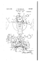
- Figure l is a side elevation of one side of the improved recording mechanism with parts in operative position.
- Fig. 2 is a side elevation of the opposite side of the recording mechanism from that shown in Fig. l.
- Fig. 3 is an enlarged vertical sectional view taken on the line 3--3 of Fig. 1, illustrating particularly the manner of mounting and operating the recording stylus in carrying out this invention.
- Fig. 4 is a vertical sectional view taken approximately on the line 4 4 of Fig. 3, and particularly illustrating the recording stylus structure and mounting in side elevation.
- Fig. 5 is a detail view of the section of film with a sound record thereon.
- a pair of supporting standards forming part of the base structure of the mechanism are indicated at 1 which extend upwardly in spaced parallel relation and support the entire mechanism in operative relation.
- a main drive shaft 2 is rotatably mounted in the standards'l and provided with a shoulder at 3 having bearing contact with the inside face of one of the standards 1 as shown in Fig. 3 and against which it is held through the medium of thrust plate 4 engaging the reduced end 5 of the shaft having bearing contact therein in order to prevent end play of the shaft and consequent lateral motion of the film passing over the sprocket roller I v construction indicated generally, by the nu-J r the pivoted end thereof carries a horizontal.
- This sprocket drive roller 6 for the film includes a pair of cooperating end sections 7 and 8 respectively which are formed with sprocket teeth 9 adapted to engage in the opening of the film 10 and drive/the same lduring the rotation of the shaft 2.
- a hardened steel disk 11 is assembled between the drive roll sections 7 and 8, the entire assembly forming the drive roll being held in assembled relation by suitable screw threaded rods 12. The purpose of the hardened steel disk will be presently pointed out.
- the standards 1 are provided with upwardly extending detachable arms as indicated at 13 from one side thereof in the upper end of which is pivotally supported a roller carrying plate 14 which is recessed throughout the central portion of one 'edge to provide a pairrof arms, and which receive the idling roller structure formed by a pair of cooperating roller sections 16 and 17 respectively independently and rotatably mounted on the shaftsection 18 in a predetermined spaced relation.
- the roller sections 16 and 17 are of hollow construction as shown to provide an internal chamber indicated at 19 while shoulders ⁇ 2O formed on the shaft 18 determine Athe position of the roller sections against which they are held to prevent endwise movement.
- suitable thrust washers 21 are positioned between the ends of the roller sections and the arms of the plate 14.
- the shaft 18 ex tends through openings formed in the ends of the arms o f said plate and is held in position' by suitable set screws 22.
- An upright projection 23 mounted on the plate adjacent arm 24 adjustably mounting theweight 25 normally applying a downward pressure on the plate 14 to move the same about its pivot and hold the roller sections 16 and 17 firm down in engagement with the film for holding the same in a true and flat relation on the surface of the drive roller structure 6.
- One end of the shaft 18 is provided with a ⁇ bore' 26 and at the 'l1-nner end of the bore an' opening extends. radially through the shaft at 27 for a purpose which will presently appear.
- roller sections 16 and 17 are provided with an lar grooves 28 adapted to receive the sprgclik drive roller assembly 6 in t e operation of the device, while the section 7 is of reduced diameter at 29 to receive the annular flange 30 on the roller assembly 6 extending from the peripheral edge of the section 8 of said roller assembly.
- the carrier plate 14 is provided with depending hangers 31 in which one end of-the recorder supporting member 32 is pivotally mounted as indicated at 32.
- the supporter recording member 32 is formed with an enlarged central opening 38 which receives the shaft 18y and within the chamber 19 the said member is formed on one side thereof with a pair of spaced projections 39 arranged in a substantially and normally horizontal plane forming bearings supports for the .recorder carrying member 40 having the spaced pin, bearing 41 so that the as of conoidal shape.
- a supporting spring 45 of curved construction has a threaded end receiving the nut 46 adapted to engage the projection 47 on the recorder supporting member 32 so that the tension applied to the recorder carrying member 40 maybe adjusted to a desired degree to produce a uniform and efficient sound record groove in a ilm strip without distortion or the recordation of mechanical sounds resulting from the operation of the recording apparatus.
- the recorder carrying member 40 is provided with an upwardly extending arm 48 projecting through the opening27 in the shaft 18 and provided with a laterally extending end portion 49 projecting outwardly junction with the recording of sound on astrip' or disk record.
- the operating rod 48 for the recorder member together Aw-ith thelate'ral extension 49 is formed of substantially resilient material so as to permit of an axial movement of the portion 49 without necessitating a pivotal connection between the rod and the recorder member, but at the same time efficiently transmitting sound vibrations applied thereto for the purpose of oscillating the recorder member on the pin bearings 41 and thereby producing an oscillation of the diamond point 44 to impress a wavering groove in the celluloid film strip in which the sound record is being made and wherein the sound record will be produced hy the horizontal undulation in the groove formed by the diamond point in said film strip.
- This lever structure 53 with the weight 55 has a substantially different period of vibration than that of the recorder mounting member 32 and in being engaged with the pin 51 on the free end portion of said plate 32, the vihation tendencies of the recorder plate will be transmitted to the lever 53 and in view of the different period of vibration of said lever, the vibrations of the recorder member 32 will be absorbed by the lever. In this way, the recorder member will be prevented from vibrating in response to the variations in consistency of the film strip and practice has shown that the recording needle or stylus will be moved over the film strip for forming a sound record groove and recording sound in said groove in a uniform even manner and thereby produce a clear and undistorted record of the sounds applied thereto.
- a suitable guide for the film is illustrated at 56 for guiding said film onto the guide sprocket rolls 6 from the reel housing 57 while suitable idler rollers 58 and 59 serve to guide the film as it leaves the recording lmechanism and to retain the same on the periphery of the drive roll for a sufficient distance to maintain the sprocket teeth in driving engagement with the film.
- the film is wound in any suitable manner on a suitable reel contained within the housing 60.
- An L-shaped arm 61 is attached to one edge of the plate 14 as shown in Fig. 2 and extends forwardly and downwardly and terminates in close proximity to the upper end of one side of one of the standards 1.
- the lower end of the L-shaped arm 61 carries a manually operable hand lever 62 having a cam hook 63 thereon which is adapted for engagement with the upper end of the standard l so that in the position shown in dotted lines in Fig. 2, the cam will operate the arm 61 and move the carrier plate 14 on its pivot to raise the roller structure.
- the other elements carried by said arm include the recording stylus carried above the drive roller assembly 6 and the film thereon so that the film may be fed into the machine in a convenient manner and also to prevent the recorder from engaging and forming the sound groove in the film.
- a standard moving picture film is used as shown in Fig. 5 which includes a series of picture squares 65 positioned in the central portion throughout the length of the film 66 while the edge portion is formed with the vusual series of openings 67 for receiving the sprocket teeth for the driving sprocket for the film.
- the picture squares 65 are always substantially larger than the actual projected'portion of the picture in view of the fact that the opening in the film gate is always smaller in size than the size of the picture squares.
- the film is held in contact with the surface of the drive roll 6 until it passes under the idler 58.
- the fil'm then extends over the idler roller 59y and is drawn into the casing 60 for winding on a suitable reel.
- thelever 62 isithen operated to permit the f roller sections 16 and 17 to be lowered into engagement with the film as indicated at 10 in Fig. 3 which will also permit the recording point 44 to engage the film in a free manner for recording sound waves therein.
- the Weight of the roller sections 16 and 17 in addition to the weight of the carrier plate 14 v and the force applied thereto through the Weight on the arm 24 will serve to force the lm down into intimate contact with the for receiving the record of the sound waves during the operation of the recorder member'thereby.
- the -driver roller 6 as well as the roll secy tions 16 and 17 in assembled relation are of such construction that the faces thereof engaging the film' are of a width slightly less than that of the film so that in the passage of said film between the said rollers, one edge portion thereof will project beyond the ends of each of the roller structures.
- a bracket 69 is mounted on one of the standards 1 as shown in'Figs.
- the construction of the recording mechanism is of such acharacter that the point of engagement of the diamond point 44: with the motion picture film will be in the same transverse alinement with the point of engagement of the roller sections 16- and 17 with the film and the point at which the film is held in intimate contact with the surface of the drive roll 6, so that it may not warp, twist, or have any lateral movement under the recording stylus. rlhe construction therefore, guides the film at the point of engagement of the recorder therewith in a predetermined mannerso that an efficient and clear sound record may be made in the film.
- a hardened steel disk 11 is mounted between the drive roll sections 6 and 8 and the peripheral surface thereof coincides with the surface of the roll section 7. Itwill be noted that in Fig. 3 the hardened steel disk is in alignment with the recording stylus, thus providing a very regular and hardened surface beneath v.the ilm during the recording operation.
- the roll sections 7 and 8 are necessarily made of soft material to permit the cutting of the sprocket teeth therein but this material may be subject to warping and twisting such as would interfere with proper recording of sound.
- the roll sections, 6, 7 and 8 were hardened after the teeth were cut -there would be such warping and shrinkage of the sections and sprocket teeth as to interfere with the proper running of the lmthrough the recorder.
- the arrangement provided byapplicant with the hardened steel disk 1'1 overcomes these difficulties.
- a mechanism for recording sound on a strip comprising, in combination, a support for the strip having a supporting surface adapted to 4travel with the strip throughout a predetermined zone, and adapted for enmy invention, what gagement bya recording mechanism operable to engage said strip within said predetermined zone, and means.
- a sound recording mechanism having a needle, adapted for engagement with said strip, and rotatable means for cooperation with said rotatable support adapted to engage the film in the zone of engagement with said support, and to retain said film in intimate bearing contact with said support adjacent the point of engagement of the recording needle with said strip and including a rigid guide carried by said rotatable support forming an abutment for one edge of the strip and a yieldable guide engageable with the opposite edge thereof anism having a recording needle operable to engage said film strip at the point of engagement thereof with said support, and means substantially encircling said recording mechanism for engagement with said strip adapted to retain the same in engagement with said support and said recording mechamsm.
- a mechanism for recording sound on astrip a cylindrical supporting member for the strip mounted for rotative movement, with the strip arranged on a. portion of the surface thereof in traveling movement thereover, whereby to support the strip in sound recording position with a recording mechanism having a recording needle operable to engage said film strip at the point of engagement of said strip with said support, and means encircling said recording mechanism for engagement with said strip adapted to retain the same in predetermined relation with said support and said recording mechanism, and cooperating means adapted to guide said film strip on said supportin its movement thereover for retaining said strip in engagement with said support.
- a mechanism for recording sound on a strip comprising a support for the strip permittingmovement of the strip over said support, whereby to arrange the strip in sound recording position with a recording mechanism having a recording needle adapted for engagement with said strip on said support, and gravity actuated means' attached-'to said recording mechanism operable to substantially eliminate and absorb mechanical vib-rations impressed on said recording mechanism and prevent the recordation thereof onsaid strip.
- a mechanism for recording sound on a strip comprising a support for the strip permitting movement of the strip over said support, whereby to arrange the strip in sound recordingposition with a recording mechanism having a recording needle adapted for engagement with said strip on said support, means attached to said recording mechanism operable to eliminate and absorb mechanical vibrations impressed on said recording mechanism and prevent the recordation thereof on said strip, and means rencircling said recording mechanism for maintaining said strip in uniform engagement with said support in the zone of said recording needle.
- a sound recording mechanism for strip material comprising a support having means for feeding and guiding the material to receive a sound impression, a. recording mechanism supporting member pivotally mounted on said support, means carried thereby for attaching the reI cording mechanism for oscillatory movement thereof t ansversely to the path of travel of the strip and means for retaining the supporting member against transverse movement.
- a mounting for sound recording mechanism for strip material comprising a support having means for feeding and guiding the material to receive the sound impressions, a recording mechanism supporting member pivotally mounted on said support, means carried thereby for attaching the recording mechanism for oscillatory movement thereof transversely to the path of travel of the strip, means for retaining the supporting member against transverse movement and' means arranged at the free end of said member yieldably permitting vertical movement thereof.
- a mounting for a sound recording mechanism for strip material comprising a suppport having means for feeding and guidingthe material to receive the sound impressions, a recording mechanism supporting member pivotally mounted on said support, means carried thereby for attaching the recording mechanism for oscillatory movement thereof transversely to the path of travel of the strip, guide means engaging the free end of said member preventing transverse movement thereof and an adjustable weightcarried by said free end of the member yieldably restraining the same against upward move- ⁇ ment.
- Mechanism for impressing a sound record in celluloid or like substance comprising, in combination, a support for the celluloid record, a recording member adapted to be actuated from a sound vibrated member, means for moving the celluloid record and recording member relatively, and means for preventing mechanical vibrations other than the sound vibrations from affecting the sound record to an extent that will impair the sound record.
- Mechanism for impressing a sound rec- Ordin celluloid comprising, in combination, a support for the celluloid record, a recording member adapted to be actuated from a sound vibrator-yV member, means for moving the celluloid record and recording member relatively,.and means for automatically compensating for variations in the consistency of uniformity of the celluloid record.
- Mechanism for impressing a sound record in celluloid comprising, in combination, a support for the celluloid record, a recording member adapted to be actuated from a sound vibratory member, means for moving the celluloid record and recording member relatively, a support for the recording member permitting movement thereof transverse to l the path of relative movement between record and recording member, and a resilient colinction between the sound Vibrated membe a d the recording member.
- a mechanlsm for recording sound on strip ⁇ s of material said mechanism com'prising a support, means carried thereby for feeding and guiding a strip of material, a recording mechanism, a member pivotally mounted on said support and carrying the recording mechanism, the recording mechanism bein mounted to oscillate in a direction transverse y to the path of travel of the strip, and-sound vibrated means for actuating the recording mechanism.
Landscapes
- Registering, Tensioning, Guiding Webs, And Rollers Therefor (AREA)
Description
Filed March 1, 1926 2 sheets-sheet 1 July 21, 1931. F. voN MADALER SOUND `RECORDING MECHANI SM 2 Sheets-Sheet 2 Filed March 1, 1926 @Innung Patented July 21, 1931 FERDINAND VON MADALER, OF HAMPTON BAYS, NEW YORK, ASSIGNOR, BY MESNE ASSIGNMENTS, T VISIONOLA MFG. CORPORATION, OF NEW YORK, N. Y., A CORPO- RATON OF DELAWARE SOUND RECORDING MECHANISM Application filed March 1, 1926. serial No. 91,483.
This invention relates to improvements in sound recording mechanism, and to a mechanism of this character more particularly adapted for use in recording sounds directly on standard motion picture strips in a cold state during the movement of the film strip through the mechanism.
-An objectof this invention is to provide a mechanism adapted :to efliciently record' sound on a standard motion picture Celluloid film strip in a cold state during the movement of the film strip through the mechanism, and which utilizes the small space between the opening for the sprocket teeth and the edge -of the picture surface of the film for the sound record groove.
Another object of the invention is to provide a mechanism for recording the sound on a standard motion picture film strip in the cold state in which in the movement of the film through the mechanism the recording needle is operated in a uniform manner by the sound vibrations to be recorded in the strip and provided with suitable controlling mechanism to force the needle'nto the strip during the recording operation and prevent the same from scratching the film and being vibrated for recording undesirable vibrations of the mechanical structure of the recording mechanism.
The invention further comprehends the efficient recording of sound on a standard motion picture film strip in al cold state by impressing the sound record in the strip with the provision of suitable means for producing a uniform operation of the strip under the sound recording needle by providing mechanism to rigidly hold and guide the film strip in a predetermined manner under said recording needle.
This invention further provides for the construction of a l recording mechanism adapted to uniformly feed a film strip therethrough, preferably a standard motion picture film strip for receiving a sound recordy from the recording-mechanism forming part ofthe device which is especially constructed and adapted for operation with sound amplifying mechanism and sound recording mechanisms of any desired type, preferably electrically operated mechanism by means of which the sound transmitted is efficiently recorded in the film strip without appreciable mechanical noise or the recordation of undesirable sounds.
The invention comprehends numerous other objects resulting from the details of construction and operation of the parts in the production of eiiicient and clear sound records on the motion picture strip which are 'more particularly pointed out in the following detailed description and claims, directed to the preferred construction of the invention, it being understood however, that various changes may be made in the construction and relation of the parts without departing from the spirit and scope of the invention as herein set forth.
In the drawings forming part of this application:
Figure l is a side elevation of one side of the improved recording mechanism with parts in operative position.
Fig. 2 is a side elevation of the opposite side of the recording mechanism from that shown in Fig. l.
Fig. 3 is an enlarged vertical sectional view taken on the line 3--3 of Fig. 1, illustrating particularly the manner of mounting and operating the recording stylus in carrying out this invention.
Fig. 4 is a vertical sectional view taken approximately on the line 4 4 of Fig. 3, and particularly illustrating the recording stylus structure and mounting in side elevation.
Fig. 5 is a detail view of the section of film with a sound record thereon.
A pair of supporting standards forming part of the base structure of the mechanism are indicated at 1 which extend upwardly in spaced parallel relation and support the entire mechanism in operative relation. A main drive shaft 2 is rotatably mounted in the standards'l and provided with a shoulder at 3 having bearing contact with the inside face of one of the standards 1 as shown in Fig. 3 and against which it is held through the medium of thrust plate 4 engaging the reduced end 5 of the shaft having bearing contact therein in order to prevent end play of the shaft and consequent lateral motion of the film passing over the sprocket roller I v construction indicated generally, by the nu-J r the pivoted end thereof carries a horizontal.
meral 6. This sprocket drive roller 6 for the filmincludes a pair of cooperating end sections 7 and 8 respectively which are formed with sprocket teeth 9 adapted to engage in the opening of the film 10 and drive/the same lduring the rotation of the shaft 2.
A hardened steel disk 11 is assembled between the drive roll sections 7 and 8, the entire assembly forming the drive roll being held in assembled relation by suitable screw threaded rods 12. The purpose of the hardened steel disk will be presently pointed out.
The standards 1 are provided with upwardly extending detachable arms as indicated at 13 from one side thereof in the upper end of which is pivotally supported a roller carrying plate 14 which is recessed throughout the central portion of one 'edge to provide a pairrof arms, and which receive the idling roller structure formed by a pair of cooperating roller sections 16 and 17 respectively independently and rotatably mounted on the shaftsection 18 in a predetermined spaced relation. The roller sections 16 and 17 are of hollow construction as shown to provide an internal chamber indicated at 19 while shoulders `2O formed on the shaft 18 determine Athe position of the roller sections against which they are held to prevent endwise movement. For this purpose suitable thrust washers 21 are positioned between the ends of the roller sections and the arms of the plate 14. The shaft 18 ex tends through openings formed in the ends of the arms o f said plate and is held in position' by suitable set screws 22. An upright projection 23 mounted on the plate adjacent arm 24 adjustably mounting theweight 25 normally applying a downward pressure on the plate 14 to move the same about its pivot and hold the roller sections 16 and 17 firm down in engagement with the film for holding the same in a true and flat relation on the surface of the drive roller structure 6. One end of the shaft 18 is provided with a`bore' 26 and at the 'l1-nner end of the bore an' opening extends. radially through the shaft at 27 for a purpose which will presently appear. Each of these roller sections 16 and 17 are provided with an lar grooves 28 adapted to receive the sprgclik drive roller assembly 6 in t e operation of the device, while the section 7 is of reduced diameter at 29 to receive the annular flange 30 on the roller assembly 6 extending from the peripheral edge of the section 8 of said roller assembly.
The carrier plate 14 is provided with depending hangers 31 in which one end of-the recorder supporting member 32 is pivotally mounted as indicated at 32. Thisrecorder et teeth on the the guide plate 36 mounted on the supporting arm 37 secured to one of the standards 1. This provides a mounting for the recorder which will prevent lateral movement thereof as well as vibration which would cause oscillation of the recorder member and the recordation of undesirable sound in the sound record being recorded on the ilm strip.
The supporter recording member 32 is formed with an enlarged central opening 38 which receives the shaft 18y and within the chamber 19 the said member is formed on one side thereof with a pair of spaced projections 39 arranged in a substantially and normally horizontal plane forming bearings supports for the .recorder carrying member 40 having the spaced pin, bearing 41 so that the as of conoidal shape. A supporting spring 45 of curved construction has a threaded end receiving the nut 46 adapted to engage the projection 47 on the recorder supporting member 32 so that the tension applied to the recorder carrying member 40 maybe adjusted to a desired degree to produce a uniform and efficient sound record groove in a ilm strip without distortion or the recordation of mechanical sounds resulting from the operation of the recording apparatus.
The recorder carrying member 40 is provided with an upwardly extending arm 48 projecting through the opening27 in the shaft 18 and provided with a laterally extending end portion 49 projecting outwardly junction with the recording of sound on astrip' or disk record. The operating rod 48 for the recorder member together Aw-ith thelate'ral extension 49 is formed of substantially resilient material so as to permit of an axial movement of the portion 49 without necessitating a pivotal connection between the rod and the recorder member, but at the same time efficiently transmitting sound vibrations applied thereto for the purpose of oscillating the recorder member on the pin bearings 41 and thereby producing an oscillation of the diamond point 44 to impress a wavering groove in the celluloid film strip in which the sound record is being made and wherein the sound record will be produced hy the horizontal undulation in the groove formed by the diamond point in said film strip.
As the character of the celluloid film strip in which the sound record is made by this invention is of substantially tough and varying intensity and as it is sometimes of a rather sticky nature, it has been found necessary to provide means to prevent the vibration of the recorder carrying member 32 and consequently the impression of waves in the record not produced by the sound, but by the oscillation of the plate caused by the unevenness and stickiness of the material of the film strip. For this purpose a pair of pins eX- tend from opposite sides of the projection 34 of the plate 32 as indicated at 51 over which is engaged the bifurcated hook pin of a head 52 to the lower end of which is pivotally connected a lever 53 pivotally mounted in the supporting arm 37 by means of the transverse pin 53 and having a substantially long arm 54 carrying the adjustable weight 55 thereon.
This lever structure 53 with the weight 55 has a substantially different period of vibration than that of the recorder mounting member 32 and in being engaged with the pin 51 on the free end portion of said plate 32, the vihation tendencies of the recorder plate will be transmitted to the lever 53 and in view of the different period of vibration of said lever, the vibrations of the recorder member 32 will be absorbed by the lever. In this way, the recorder member will be prevented from vibrating in response to the variations in consistency of the film strip and practice has shown that the recording needle or stylus will be moved over the film strip for forming a sound record groove and recording sound in said groove in a uniform even manner and thereby produce a clear and undistorted record of the sounds applied thereto.
A suitable guide for the film is illustrated at 56 for guiding said film onto the guide sprocket rolls 6 from the reel housing 57 while suitable idler rollers 58 and 59 serve to guide the film as it leaves the recording lmechanism and to retain the same on the periphery of the drive roll for a sufficient distance to maintain the sprocket teeth in driving engagement with the film. The film is wound in any suitable manner on a suitable reel contained within the housing 60.
An L-shaped arm 61 is attached to one edge of the plate 14 as shown in Fig. 2 and extends forwardly and downwardly and terminates in close proximity to the upper end of one side of one of the standards 1. The lower end of the L-shaped arm 61 carries a manually operable hand lever 62 having a cam hook 63 thereon which is adapted for engagement with the upper end of the standard l so that in the position shown in dotted lines in Fig. 2, the cam will operate the arm 61 and move the carrier plate 14 on its pivot to raise the roller structure. The other elements carried by said arm include the recording stylus carried above the drive roller assembly 6 and the film thereon so that the film may be fed into the machine in a convenient manner and also to prevent the recorder from engaging and forming the sound groove in the film.
In the operation of this recording mechanism, a standard moving picture film is used as shown in Fig. 5 which includes a series of picture squares 65 positioned in the central portion throughout the length of the film 66 while the edge portion is formed with the vusual series of openings 67 for receiving the sprocket teeth for the driving sprocket for the film. The picture squares 65 are always substantially larger than the actual projected'portion of the picture in view of the fact that the opening in the film gate is always smaller in size than the size of the picture squares. In addition, there is aslight ,space between the edges of the picture squares and the edge portion of' the film provided with the openings 67 which does not come in contact with the mechanism for driving and retaining the film in passing through a motion picture projector, and which face is used by the present invention for receiving the sound record on the celluloid side of the film which is the back side, so that it will not be projected through the opening in thefilm gate in the projection of the pictures and also will i be free of engagement with the driving apparatus for the film. In this way a sound record canl be placed on a standard motion picture film which will not be affected or damaged in the use, of the film. The sound groove is indicated in Fig. 5 by the numeral 68. The film is fed from the reel within the housing 57 through the film guide 56 and between the guide roll 6 and the idler roller sections 16 and 17 respectively in the manner as illustrated in Fig. 4.
The film is held in contact with the surface of the drive roll 6 until it passes under the idler 58. The fil'm then extends over the idler roller 59y and is drawn into the casing 60 for winding on a suitable reel.
After the film is fed through the recording i' device as just described, during which time the lever 62 is in the full line position of Fig.
2, thelever 62 isithen operated to permit the f roller sections 16 and 17 to be lowered into engagement with the film as indicated at 10 in Fig. 3 which will also permit the recording point 44 to engage the film in a free manner for recording sound waves therein. The Weight of the roller sections 16 and 17 in addition to the weight of the carrier plate 14 v and the force applied thereto through the Weight on the arm 24 will serve to force the lm down into intimate contact with the for receiving the record of the sound waves during the operation of the recorder member'thereby. I t The -driver roller 6 as well as the roll secy tions 16 and 17 in assembled relation are of such construction that the faces thereof engaging the film' are of a width slightly less than that of the film so that in the passage of said film between the said rollers, one edge portion thereof will project beyond the ends of each of the roller structures. A bracket 69 is mounted on one of the standards 1 as shown in'Figs. 2 and 3, which is provided with a recess 70 slidably receiving the plunger 71 having the disk thereon indicated at 72 which is projected by the spring 73 outwardly frpm the bracket and toward the ends of the rollers 6 and 16 for engagement with the edge of the moving picture film in order to hold the same against lateral motion between the rollers and in engagement with theflange 30 of the drive roll G.
By the construction of the recorder mechanism as above described, it should be clearly understood thatthe rolls 16 and 17 as well as the sprocket roller 6 are held against end movement in the standard 1 as well as relative to each other bythe provision of suitable structural elements to prevent end play in the structure. It will also be clear that the film in beingpassed between 'the rolls is held in a fiat manner and also prevented .from moving laterally relative tothe faces of the rollers in order-that the sound record may be impressed an`d formed -in the moving picture strip in a most efficient manner and without the recording of mechanical or other undesirable vibrations. v
The construction of the recording mechanism is of such acharacter that the point of engagement of the diamond point 44: with the motion picture film will be in the same transverse alinement with the point of engagement of the roller sections 16- and 17 with the film and the point at which the film is held in intimate contact with the surface of the drive roll 6, so that it may not warp, twist, or have any lateral movement under the recording stylus. rlhe construction therefore, guides the film at the point of engagement of the recorder therewith in a predetermined mannerso that an efficient and clear sound record may be made in the film. v
As pointed out above, a hardened steel disk 11 is mounted between the drive roll sections 6 and 8 and the peripheral surface thereof coincides with the surface of the roll section 7. Itwill be noted that in Fig. 3 the hardened steel disk is in alignment with the recording stylus, thus providing a very regular and hardened surface beneath v.the ilm during the recording operation. The roll sections 7 and 8 are necessarily made of soft material to permit the cutting of the sprocket teeth therein but this material may be subject to warping and twisting such as would interfere with proper recording of sound. Certainly if the roll sections, 6, 7 and 8 were hardened after the teeth were cut -there would be such warping and shrinkage of the sections and sprocket teeth as to interfere with the proper running of the lmthrough the recorder. The arrangement provided byapplicant with the hardened steel disk 1'1 overcomes these difficulties.
The particular construction of this mechanism will eliminate the noises caused by vibration of the mechanical parts of the device andit has been found from actual experience, that a very clear sound record is produced in the lIn. i/ l Having thus described I claim as new is 1 A mechanism for recording sound on a strip, comprising, in combination, a support for the strip having a supporting surface adapted to 4travel with the strip throughout a predetermined zone, and adapted for enmy invention, what gagement bya recording mechanism operable to engage said strip within said predetermined zone, and means. cooperating with said support for guiding the strip in a predetermined path, including a guide yieldably engaging one edgeof the strip for retaining with throughout a predetermined Zonev in sound recording position with4 a sound recording mechanism having a needle, adapted for engagement with said strip, and rotatable means for cooperation with said rotatable support adapted to engage the film in the zone of engagement with said support, and to retain said film in intimate bearing contact with said support adjacent the point of engagement of the recording needle with said strip and including a rigid guide carried by said rotatable support forming an abutment for one edge of the strip and a yieldable guide engageable with the opposite edge thereof anism having a recording needle operable to engage said film strip at the point of engagement thereof with said support, and means substantially encircling said recording mechanism for engagement with said strip adapted to retain the same in engagement with said support and said recording mechamsm.
4. A mechanism for recording sound on astrip, a cylindrical supporting member for the strip mounted for rotative movement, with the strip arranged on a. portion of the surface thereof in traveling movement thereover, whereby to support the strip in sound recording position with a recording mechanism having a recording needle operable to engage said film strip at the point of engagement of said strip with said support, and means encircling said recording mechanism for engagement with said strip adapted to retain the same in predetermined relation with said support and said recording mechanism, and cooperating means adapted to guide said film strip on said supportin its movement thereover for retaining said strip in engagement with said support.
5. A mechanism for recording sound on a strip, comprising a support for the strip permittingmovement of the strip over said support, whereby to arrange the strip in sound recording position with a recording mechanism having a recording needle adapted for engagement with said strip on said support, and gravity actuated means' attached-'to said recording mechanism operable to substantially eliminate and absorb mechanical vib-rations impressed on said recording mechanism and prevent the recordation thereof onsaid strip.
6. A mechanism for recording sound on a strip comprising a support for the strip permitting movement of the strip over said support, whereby to arrange the strip in sound recordingposition with a recording mechanism having a recording needle adapted for engagement with said strip on said support, means attached to said recording mechanism operable to eliminate and absorb mechanical vibrations impressed on said recording mechanism and prevent the recordation thereof on said strip, and means rencircling said recording mechanism for maintaining said strip in uniform engagement with said support in the zone of said recording needle.
7. In a mounting for a sound recording mechanism for strip material comprising a support having means for feeding and guiding the material to receive a sound impression, a. recording mechanism supporting member pivotally mounted on said support, means carried thereby for attaching the reI cording mechanism for oscillatory movement thereof t ansversely to the path of travel of the strip and means for retaining the supporting member against transverse movement.
8. In a mounting for sound recording mechanism for strip material comprising a support having means for feeding and guiding the material to receive the sound impressions, a recording mechanism supporting member pivotally mounted on said support, means carried thereby for attaching the recording mechanism for oscillatory movement thereof transversely to the path of travel of the strip, means for retaining the supporting member against transverse movement and' means arranged at the free end of said member yieldably permitting vertical movement thereof.
9. In a mounting for a sound recording mechanism for strip material comprising a suppport having means for feeding and guidingthe material to receive the sound impressions, a recording mechanism supporting member pivotally mounted on said support, means carried thereby for attaching the recording mechanism for oscillatory movement thereof transversely to the path of travel of the strip, guide means engaging the free end of said member preventing transverse movement thereof and an adjustable weightcarried by said free end of the member yieldably restraining the same against upward move-` ment.
l0. Mechanism for impressing a sound record in celluloid or like substance comprising, in combination, a support for the celluloid record, a recording member adapted to be actuated from a sound vibrated member, means for moving the celluloid record and recording member relatively, and means for preventing mechanical vibrations other than the sound vibrations from affecting the sound record to an extent that will impair the sound record.
l1. Mechanism for impressing a sound rec- Ordin celluloid comprising, in combination, a support for the celluloid record, a recording member adapted to be actuated from a sound vibrator-yV member, means for moving the celluloid record and recording member relatively,.and means for automatically compensating for variations in the consistency of uniformity of the celluloid record.
12. Mechanism for impressing a sound record in celluloid comprising, in combination, a support for the celluloid record, a recording member adapted to be actuated from a sound vibratory member, means for moving the celluloid record and recording member relatively, a support for the recording member permitting movement thereof transverse to l the path of relative movement between record and recording member, and a resilient colinction between the sound Vibrated membe a d the recording member.
13. A mechanlsm for recording sound on strip\s of material, said mechanism com'prising a support, means carried thereby for feeding and guiding a strip of material, a recording mechanism, a member pivotally mounted on said support and carrying the recording mechanism, the recording mechanism bein mounted to oscillate in a direction transverse y to the path of travel of the strip, and-sound vibrated means for actuating the recording mechanism.
In testimony whereof I aiix my signature.
FERDINAND voN MADALER.
Priority Applications (1)
| Application Number | Priority Date | Filing Date | Title |
|---|---|---|---|
| US91483A US1815692A (en) | 1926-03-01 | 1926-03-01 | Sound recording mechanism |
Applications Claiming Priority (1)
| Application Number | Priority Date | Filing Date | Title |
|---|---|---|---|
| US91483A US1815692A (en) | 1926-03-01 | 1926-03-01 | Sound recording mechanism |
Publications (1)
| Publication Number | Publication Date |
|---|---|
| US1815692A true US1815692A (en) | 1931-07-21 |
Family
ID=22228017
Family Applications (1)
| Application Number | Title | Priority Date | Filing Date |
|---|---|---|---|
| US91483A Expired - Lifetime US1815692A (en) | 1926-03-01 | 1926-03-01 | Sound recording mechanism |
Country Status (1)
| Country | Link |
|---|---|
| US (1) | US1815692A (en) |
Cited By (3)
| Publication number | Priority date | Publication date | Assignee | Title |
|---|---|---|---|---|
| US2468025A (en) * | 1943-09-27 | 1949-04-26 | Manufacturers Machine & Tool C | Motion-picture film mechanism |
| US2550826A (en) * | 1948-04-05 | 1951-05-01 | Hattie B Kuhlik | Anvil for sound recording and reproducing machines |
| US2867439A (en) * | 1954-03-25 | 1959-01-06 | Heurtier & Cie Ets | Sound reading device for kinematographic projectors |
-
1926
- 1926-03-01 US US91483A patent/US1815692A/en not_active Expired - Lifetime
Cited By (3)
| Publication number | Priority date | Publication date | Assignee | Title |
|---|---|---|---|---|
| US2468025A (en) * | 1943-09-27 | 1949-04-26 | Manufacturers Machine & Tool C | Motion-picture film mechanism |
| US2550826A (en) * | 1948-04-05 | 1951-05-01 | Hattie B Kuhlik | Anvil for sound recording and reproducing machines |
| US2867439A (en) * | 1954-03-25 | 1959-01-06 | Heurtier & Cie Ets | Sound reading device for kinematographic projectors |
Similar Documents
| Publication | Publication Date | Title |
|---|---|---|
| US1815692A (en) | Sound recording mechanism | |
| US2096113A (en) | Sound recording and reproducing | |
| US2115503A (en) | Mechanism for winding endless films | |
| US2323215A (en) | Sound recorder and reproducer | |
| US2173048A (en) | Portable sound recording and sound reproducing machine | |
| US2637561A (en) | Method and means of magnetic recording and reproducing sound | |
| US2701718A (en) | Apparatus for manipulating endless bands | |
| US2482672A (en) | Recording and projecting apparatus | |
| US2586666A (en) | Sound-on-film recording and reproducing machine | |
| US1758559A (en) | Sound recording and reproducing apparatus | |
| US2237738A (en) | Sound translating equipment | |
| US2273391A (en) | Apparatus for reproducing and recording sound | |
| US2248106A (en) | Driving mechanism | |
| US1731235A (en) | Electromagnetic sound recording and reproducing machine | |
| US2261410A (en) | Sound head for motion picture machines | |
| US2032062A (en) | Apparatus for engraving sound vibrations on flexible records | |
| US2676798A (en) | Film drive filter | |
| US2092159A (en) | Roller and flywheel mount | |
| US458916A (en) | Phonograph | |
| US539212A (en) | Apparatus for reproducing phonograms | |
| US2870265A (en) | Magnetic recording device | |
| US2586600A (en) | Interlocked pressure roller and pad roller | |
| US2219731A (en) | Sound film mechanism | |
| US2840380A (en) | Magnetic recorder sound unit | |
| US1864213A (en) | Recording apparatus |