US1805723A - Electric meter protecting cabinet - Google Patents
Electric meter protecting cabinet Download PDFInfo
- Publication number
- US1805723A US1805723A US532449A US53244922A US1805723A US 1805723 A US1805723 A US 1805723A US 532449 A US532449 A US 532449A US 53244922 A US53244922 A US 53244922A US 1805723 A US1805723 A US 1805723A
- Authority
- US
- United States
- Prior art keywords
- cabinet
- shutter
- meter
- wall
- opening
- Prior art date
- Legal status (The legal status is an assumption and is not a legal conclusion. Google has not performed a legal analysis and makes no representation as to the accuracy of the status listed.)
- Expired - Lifetime
Links
- 230000001681 protective effect Effects 0.000 description 14
- 230000000717 retained effect Effects 0.000 description 2
- 230000000694 effects Effects 0.000 description 1
- 238000007373 indentation Methods 0.000 description 1
- 238000009434 installation Methods 0.000 description 1
- 238000004519 manufacturing process Methods 0.000 description 1
- 239000002184 metal Substances 0.000 description 1
- 238000006467 substitution reaction Methods 0.000 description 1
Images
Classifications
-
- G—PHYSICS
- G01—MEASURING; TESTING
- G01R—MEASURING ELECTRIC VARIABLES; MEASURING MAGNETIC VARIABLES
- G01R11/00—Electromechanical arrangements for measuring time integral of electric power or current, e.g. of consumption
- G01R11/02—Constructional details
- G01R11/04—Housings; Supporting racks; Arrangements of terminals
Definitions
- This invention relates to those cabinets or boxes which are adapted to contain switches, fusible cut-outs, meter testing instrumentalities and similar appliances, and which are designed to be protectively associated with the terminal chambers of electric meters in such manner as to conceal and protect a part of the meter and the connections between the meter and the enclosed appliance.
- the various types of meters in general use have terminal chambers of different sizes and shapes and it is frequently desirable to use the cabi nets independently of the meters. Therefore, previously it was proposed to provide the cabinets with interchangeable end walls, which end walls had openings of the correct sizes to approximately fit the respective meters with which the cabinets were to be used or which were without openings for use when the cabinets were to be used without meters associated therewith.
- the principal object of the present invention is to provide an electric appliance enclosing cabinet of the type described having means at or adjacent one of the normally fixed walls thereof, ordinarily one end wall, whereby any one of two or more meters of different sizes or shapes can be protectively associated with the cabinet, this object'being attained without providing complete interchangeable end or other walls as has been'the prior practice.
- Theforegoing object is attained by forniing one of the said normally fixed walls of the box, ordinarily an end wall, With an opening therein extending forward from a plane of the rear wall of the box which opening is at least as large as the terminal chamber portion of the largest of a series of meters, and by providing in association with the said wall a removable shutter having an opening therein extending forward from the rear edge thereof which opening is smaller than the opening in the said wall and adapted to reg ster therewith and is of such size and shape as to approximately fit for protective purposes a art, ordinarily the terminal chamber part, 0 an electric meter.
- the aforesaid wall of the cabinet that is the end wall, and the shut- 1 .ter are separate from and independent of the front cover for the cabinet, the result being that the cover is openable independently of the said wall and shut-ter so as to provide ac cess to the interior of the cabinet without disturbing the protective relationship between the shutter and the meter.
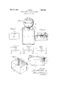
- Fig. 1 is a front view of a cabinet embodying the invention, the cabinet being in protective association with an electric meter and a portion of the front cover being broken away.
- Fig. 2 is a fragmentary View similar to Fig.
- Fig. 3 is a fragmentary perspective view of the upper end of the cabinet and shutter as shown in Fig. 2. In this view the cabinet cover and the meter are omitted.
- Fig. 4 is a Vertical sectional view through the cabinet as shown in Figs. 2 and 3, this view also showing a part of the meter. u
- Figs. 5, 6 and 7 are detail views showing different interchangeable slides or shutters which may be used in association with the cabinet for protective relation with meters of different types.
- Fig. 8 is a view similar to F igs. 5, 6 and 7 but showing a slide orshutter adapted to entirely close the end of the cabinet.
- a cabinet embodying the invention may be made of sheet metal with a back wall 1,
- the said end wall 5 is removable and is retained by the engagement of elongated indented sections 7 in the side walls which enter similarly indented sections 8 of the flanges 9 that project inward from this end wall.
- the end wall may be retained from outward movement by the engagement of indentations 10 in the side walls with perforations 11 in the flanges.
- an opening 12 which is at least sufiiciently large to be directly associated with theterininal chamber part 13 of the largest one of aseries of two or more electric meters of different sizes or shapes, the said meter being designated by M in Fig. 1.
- the said opening 12 is of such a size and shape as to approximately fit the said meter part 13 for protective purposes.
- the said part 13 of the meter 'M projects into the cabinet through the said opening 12 and approximately fits the edges of the said opening.
- the meter and the cabinet may be relatively placed and protectively associated as shown in Fig. 1 without the addition of any parts other than those already described.
- I provide, in conjunction with the wall having an opening such as 12 therein, a removable shutter for more or less restricting the effective size of the said opening.
- a meter which is different from thesaid relatively large meter M and which has a terminal chamber portion smaller than the said opening 12
- I provide in association with the cabinet wall having the said opening, that is, in association with the end wall 5, a removable plate or shutter such as 15 shown in Figs. 2, 3, 4 and 5.
- the said smaller-meter is shown at M in Fig. 2 this meter having a terminal chamber part 13'.
- the said shutter 15 is adapted to be positioned immediately adjacent the said wall 5 at the said opening 12 and preferably at the inner face of the wall.
- the said shutter 15 is provided with an opening 17 therein extending forward from the rear edge thereof which opening is smaller than the said opening 12 in the wall 5 and is in register therewith.
- the said smaller opening 17 in the plate or shutter 15 is of such size and shape as to approximately fit for protective purposes the terminal chamher part 13' of the said smaller electric meter M which is to be associated with the cabinet.
- the plate or shutter 15 is so positioned that the cover, when closed overlaps the shutter and thereby prevents removal thereof, but the shutter 15 is entirely independent of. the cover so as to permit the cover to be opened to provide access to the interior of the cabl net without disturbing the relationship between the shutter and the meter.
- the shutter When the cover is open the shutter is removable from the cabinet preferably in the forward direction at right angles to the rear wall, and pref erably it is removable independently of the cabinet wall with which it is associated.
- shutter engaging'means or plates 14 which have their edges ofi'set so as to form guide Ways for the side edges of the slide or shutters 15.
- any one of two or more meters having their terminal chamber I portions smaller than the opening 12 I provide a series of two or more plates or shutters, the said plate 15 being one of the series.
- the several plates or shutters of the series are preferably identical as to their external dimensions and are adapted to be interchangeably engaged by the aforesaid guide plates 14.
- Figs. 6 and 7 I have shown shutters 15 and 15 similar to the shutter 15 as concerns external dimensions but differing therefrom in the sizes and shapes of the openings therein.
- the shutters 15 and 15 are. provided respectively with openings 18 and 19. It will be seen that by selecting the proper one of the three shutters 15, 15 and 15 the cabinet can be readily adapted for protective association with any one of three different meters.
- depressions in the top of the free end of the cover and the up er edges ofthe shutters are so designed that W en the cover is closed the depression will bear upon the upperedge of the shutter that is in use at that time and prevent it from being lifted topermit access to the meter terminal chamber.
- the upper edges of the shutters at the middle desirably have inset sections 21 which will lie beneath the indented section of the cover.
- TlllS end wall structure comprises the end wall proper, that is, the end wall plate 5 with the guide members thereon, and it also comprises the associated shutter 15 on one of the other shutters. It will be observed that the relationship between the end wall plate and the shutter is such that the shutter is freely removable in the forward direction.
- a cabinet constructed. according to this invention is capable of being used with meters of various types and sizes or used disassociated from the meters, by the mere substitution on the end wall of the slide or closure that will give the desired protection for the electrical connections.
- These slides or closures are light and small, simple and cheap to manufacture, and easily assembled according to the conditions required to effect the necessary protection for the connections.
- Y cabinet body including connected rear and side walls, a cabinet end wall, normally positionedin fixed relationship with the rear and side walls but removable therefrom in the forward direction, the said end wall being provided with an opening therein extending forward from the rear edge thereof, a shutter adapted to be positioned immediately adjacent the end wall at the said opening, the said 1 1 shutter being removablefrom the cabinet in the forward direction and having an opening therein extending forward from the rear edge thereof which openin is smaller than the opening in the end wall and adapted to register therewith and is of such size and of the cabinet and to the said protected part of the meter, the said cover being so constructed that when closed it overlaps both the end wall and the shutter to prevent removal thereof and the said cover being openable independently of the end wall and shutter so as to provide access to the interior of the cabinet with the end and shutter in place and with the latter in protective relationship with the meter.
- An electric appliance enclosing cabinet adapted for protective relationship with an electric meter, comprising in combination, a rear wall, end and side walls positionedin normally fixed relationship with the rear wall and one of them provided with an 0 ening therein extending forward from a p ane of the said rear wall and of such size and shape as to approximately fit for protective purposes a part of a relatively large electric meter, a shutter adapted to be positioned immediately adjacent the inner face of the last said will at the said opening, the said shutter having an openin therein extending forward from the rear edge thereof which opening is smaller than the opening in the said wall and adapted to register therewith and is of such size and shape as to receive and approximately fit for protective purposes a projecting part of a smaller electric meter, means on the inner side of the last said wall for detachably holding the shutter and guiding it for removal from the cabinet in the forward direction independently of the said wall, and a front cover for the cabinet separatefrom the last said wall and from the shutter and serving when closed to prevent access to the interior of the cabinet
Landscapes
- Physics & Mathematics (AREA)
- General Physics & Mathematics (AREA)
- Casings For Electric Apparatus (AREA)
- Measuring Volume Flow (AREA)
Description
May 19, 1931. J. SACHS 1,305,723
ELECTRIC METER PROTECTING CABINET Filed Jan. 28, 1922 Patented May 19, 1931 UNITED STATES JOSEPH SACHS, OF HARTFORD, CONNECTICUT I ELECTRIC METER PROTECTING CABINET Application filed January 28, 1922. Serial No. 532,449.
This invention relates to those cabinets or boxes which are adapted to contain switches, fusible cut-outs, meter testing instrumentalities and similar appliances, and which are designed to be protectively associated with the terminal chambers of electric meters in such manner as to conceal and protect a part of the meter and the connections between the meter and the enclosed appliance. The various types of meters in general use have terminal chambers of different sizes and shapes and it is frequently desirable to use the cabi nets independently of the meters. Therefore, previously it was proposed to provide the cabinets with interchangeable end walls, which end walls had openings of the correct sizes to approximately fit the respective meters with which the cabinets were to be used or which were without openings for use when the cabinets were to be used without meters associated therewith.
The principal object of the present invention is to provide an electric appliance enclosing cabinet of the type described having means at or adjacent one of the normally fixed walls thereof, ordinarily one end wall, whereby any one of two or more meters of different sizes or shapes can be protectively associated with the cabinet, this object'being attained without providing complete interchangeable end or other walls as has been'the prior practice.
Theforegoing object is attained by forniing one of the said normally fixed walls of the box, ordinarily an end wall, With an opening therein extending forward from a plane of the rear wall of the box which opening is at least as large as the terminal chamber portion of the largest of a series of meters, and by providing in association with the said wall a removable shutter having an opening therein extending forward from the rear edge thereof which opening is smaller than the opening in the said wall and adapted to reg ster therewith and is of such size and shape as to approximately fit for protective purposes a art, ordinarily the terminal chamber part, 0 an electric meter. The aforesaid wall of the cabinet, that is the end wall, and the shut- 1 .ter are separate from and independent of the front cover for the cabinet, the result being that the cover is openable independently of the said wall and shut-ter so as to provide ac cess to the interior of the cabinet without disturbing the protective relationship between the shutter and the meter.
In addition to the aforesaid general object of the invention there are other secondary objects incidental to the main object which secondary objects will be apparent from the following specification and claims.
' In the accompanying drawings I have shown one embodiment of the invention but it will be understood that the drawings are intended for illustrative purposes only and is not to be construed as defining or limiting the scope of the invention, the claims forming a part, of this specification being relied upon for that purpose.
Of the drawings:
Fig. 1 is a front view of a cabinet embodying the invention, the cabinet being in protective association with an electric meter and a portion of the front cover being broken away.
Fig. 2 is a fragmentary View similar to Fig.
1, but showing a smaller meter and showing a shutter in place for providing protective relationship with the smaller meter.
Fig. 3 is a fragmentary perspective view of the upper end of the cabinet and shutter as shown in Fig. 2. In this view the cabinet cover and the meter are omitted.
Fig. 4 is a Vertical sectional view through the cabinet as shown in Figs. 2 and 3, this view also showing a part of the meter. u
Figs. 5, 6 and 7 are detail views showing different interchangeable slides or shutters which may be used in association with the cabinet for protective relation with meters of different types.
Fig. 8 is a view similar to F igs. 5, 6 and 7 but showing a slide orshutter adapted to entirely close the end of the cabinet.
A cabinet embodying the invention may be made of sheet metal with a back wall 1,
. side walls 2 and 3, end walls 4 and 5 and a cover 6 which is hinged to the end wall 4 and swings rearward over the end wall 5. The cover 6 is entirely separate from side walls and it may be removable therefrom although this is not essential as concerns the broader phases of the invention. Preferably,
however, and as shown the said end wall 5 is removable and is retained by the engagement of elongated indented sections 7 in the side walls which enter similarly indented sections 8 of the flanges 9 that project inward from this end wall. The end wall may be retained from outward movement by the engagement of indentations 10 in the side walls with perforations 11 in the flanges. In one of the relatively fixed walls of the box other than the said back wall 1 and preferably in the said end wall 5 there is an opening 12 which is at least sufiiciently large to be directly associated with theterininal chamber part 13 of the largest one of aseries of two or more electric meters of different sizes or shapes, the said meter being designated by M in Fig. 1. Preferably the said opening 12 is of such a size and shape as to approximately fit the said meter part 13 for protective purposes. As shown in Fig. 1 the said part 13 of the meter 'M projects into the cabinet through the said opening 12 and approximately fits the edges of the said opening. When the said relatively large meter M is to be used and when the opening 12 is of such size and shape as to approximately fit the terminal chamber part thereof, the meter and the cabinet may be relatively placed and protectively associated as shown in Fig. 1 without the addition of any parts other than those already described.
In accordance with the invention I provide, in conjunction with the wall having an opening such as 12 therein, a removable shutter for more or less restricting the effective size of the said opening. When a meter is to be used which is different from thesaid relatively large meter M and which has a terminal chamber portion smaller than the said opening 12 I provide in association with the cabinet wall having the said opening, that is, in association with the end wall 5, a removable plate or shutter such as 15 shown in Figs. 2, 3, 4 and 5. The said smaller-meter is shown at M in Fig. 2 this meter having a terminal chamber part 13'. The said shutter 15 is adapted to be positioned immediately adjacent the said wall 5 at the said opening 12 and preferably at the inner face of the wall. The said shutter 15 is provided with an opening 17 therein extending forward from the rear edge thereof which opening is smaller than the said opening 12 in the wall 5 and is in register therewith. The said smaller opening 17 in the plate or shutter 15 is of such size and shape as to approximately fit for protective purposes the terminal chamher part 13' of the said smaller electric meter M which is to be associated with the cabinet.
The plate or shutter 15 is so positioned that the cover, when closed overlaps the shutter and thereby prevents removal thereof, but the shutter 15 is entirely independent of. the cover so as to permit the cover to be opened to provide access to the interior of the cabl net without disturbing the relationship between the shutter and the meter. When the cover is open the shutter is removable from the cabinet preferably in the forward direction at right angles to the rear wall, and pref erably it is removable independently of the cabinet wall with which it is associated. As shown there are provided at the inside of the end wall 5 and at each side of the opening 12 shutter engaging'means or plates 14 which have their edges ofi'set so as to form guide Ways for the side edges of the slide or shutters 15.
lVhen it is desired to make provision for the use of any one of two or more meters having their terminal chamber I portions smaller than the opening 12 I provide a series of two or more plates or shutters, the said plate 15 being one of the series. The several plates or shutters of the series are preferably identical as to their external dimensions and are adapted to be interchangeably engaged by the aforesaid guide plates 14. In Figs. 6 and 7 I have shown shutters 15 and 15 similar to the shutter 15 as concerns external dimensions but differing therefrom in the sizes and shapes of the openings therein. The shutters 15 and 15 are. provided respectively with openings 18 and 19. It will be seen that by selecting the proper one of the three shutters 15, 15 and 15 the cabinet can be readily adapted for protective association with any one of three different meters. While I have shown three interchangeable shutters it will beunderstood that I do not so limit myself and that any desired or necessary number can be provided. When the aforesaid opening 12 in the main end wall 5 is of such a size and shape as to approximately fit for protective purposes the terminal chamber part of the said relatively large meter M as already described, the said meter can be directly associated with the end wall without the necessity for using any shutter. Thus I am enabled to provide for one meter in addition to those corresponding to the several shutters. For example, I can provide for four different meters with only three interchangeable shutters.
It is frequently desirable to provide for the complete protection of the parts within the cabinet when the cabinet is used without direct association with a meter. This condition may arise when the cabinet and the en closed appliance are first installed and prior to the installation of the meter or it may arise at some later time when the meter is removed for any reason. In such cases the complete protection of the interior of the cabinet can be obtained by using a shutter such as shown in Fig. 8, in lieu of one of the shutters 15, 15 or 15". The shutter 15 is imperforate and therefore serves-inv conjunction with the end wall to entirely close the corresponding end of the cabinet.
It is common to form depressions in the top of the free end of the cover and the up er edges ofthe shutters are so designed that W en the cover is closed the depression will bear upon the upperedge of the shutter that is in use at that time and prevent it from being lifted topermit access to the meter terminal chamber. The upper edges of the shutters at the middle desirably have inset sections 21 which will lie beneath the indented section of the cover. These inset sections of the shutters besides forming substantial stops to prevent the lifting of the shutters when the cover is closed, provide means which can be conveniently grasped for handling the shutters.
It will be observed that, when the end wall 5 is made separable from the other parts of the cabinet as already described, the said wall together with a shutter associated therewith constitute a separate end wall structure which may if desired be manufactured and sold separately and which may be installed in previously or separately manufactured cabi-' nets. TlllS end wall structure comprises the end wall proper, that is, the end wall plate 5 with the guide members thereon, and it also comprises the associated shutter 15 on one of the other shutters. It will be observed that the relationship between the end wall plate and the shutter is such that the shutter is freely removable in the forward direction.
A cabinet constructed. according to this invention is capable of being used with meters of various types and sizes or used disassociated from the meters, by the mere substitution on the end wall of the slide or closure that will give the desired protection for the electrical connections. These slides or closures are light and small, simple and cheap to manufacture, and easily assembled according to the conditions required to effect the necessary protection for the connections.
The invention claimed is 1-- 1. An electric appliance enclosing cabinet adapted for protective relationship with an electric meter, comprising in combination, a
Y cabinet body including connected rear and side walls, a cabinet end wall, normally positionedin fixed relationship with the rear and side walls but removable therefrom in the forward direction, the said end wall being provided with an opening therein extending forward from the rear edge thereof, a shutter adapted to be positioned immediately adjacent the end wall at the said opening, the said 1 1 shutter being removablefrom the cabinet in the forward direction and having an opening therein extending forward from the rear edge thereof which openin is smaller than the opening in the end wall and adapted to register therewith and is of such size and of the cabinet and to the said protected part of the meter, the said cover being so constructed that when closed it overlaps both the end wall and the shutter to prevent removal thereof and the said cover being openable independently of the end wall and shutter so as to provide access to the interior of the cabinet with the end and shutter in place and with the latter in protective relationship with the meter.
2. An electric appliance enclosing cabinet adapted for protective relationship with an electric meter, comprising in combination, a rear wall, end and side walls positionedin normally fixed relationship with the rear wall and one of them provided with an 0 ening therein extending forward from a p ane of the said rear wall and of such size and shape as to approximately fit for protective purposes a part of a relatively large electric meter, a shutter adapted to be positioned immediately adjacent the inner face of the last said will at the said opening, the said shutter having an openin therein extending forward from the rear edge thereof which opening is smaller than the opening in the said wall and adapted to register therewith and is of such size and shape as to receive and approximately fit for protective purposes a projecting part of a smaller electric meter, means on the inner side of the last said wall for detachably holding the shutter and guiding it for removal from the cabinet in the forward direction independently of the said wall, and a front cover for the cabinet separatefrom the last said wall and from the shutter and serving when closed to prevent access to the interior of the cabinet and to the said protected part of the meter, the sa-id cover being so constructed that when closed it overlaps the shutter to prevent removal thereof and the said cover being openable independently of the said wall and shutter so as CERTIFICATE or oommcrloN.
Patent No. 4,805,723; GrantedMay 19, 1931; to
JOSEPH SACHS;
It is hereby certified that error appears in the -printed specification of the above numliered patent requiring correction as follows: Page 3, line 57, claim 1, strike out the commaa'fter theword "wall", and line 83, after "end" insert the word wall; and that the said Letters Patent should be read with these corrections therein that the same may conform to the record of the case in the Patent Office. 4
Signed and sealed this 7th .day of July, A. D. 1931-. v
M. J. Moore,
(Seal) Acting Commissioner of Patents.
Priority Applications (1)
| Application Number | Priority Date | Filing Date | Title |
|---|---|---|---|
| US532449A US1805723A (en) | 1922-01-28 | 1922-01-28 | Electric meter protecting cabinet |
Applications Claiming Priority (1)
| Application Number | Priority Date | Filing Date | Title |
|---|---|---|---|
| US532449A US1805723A (en) | 1922-01-28 | 1922-01-28 | Electric meter protecting cabinet |
Publications (1)
| Publication Number | Publication Date |
|---|---|
| US1805723A true US1805723A (en) | 1931-05-19 |
Family
ID=24121859
Family Applications (1)
| Application Number | Title | Priority Date | Filing Date |
|---|---|---|---|
| US532449A Expired - Lifetime US1805723A (en) | 1922-01-28 | 1922-01-28 | Electric meter protecting cabinet |
Country Status (1)
| Country | Link |
|---|---|
| US (1) | US1805723A (en) |
-
1922
- 1922-01-28 US US532449A patent/US1805723A/en not_active Expired - Lifetime
Similar Documents
| Publication | Publication Date | Title |
|---|---|---|
| US10276319B1 (en) | Switch cover guard | |
| US3743892A (en) | Closure means for unoccupied circuit breaker opening in a panel board | |
| US2106003A (en) | Terminal box | |
| US3467763A (en) | Safety cover for electrical outlets | |
| US2441643A (en) | Protective electrical outlet receptacle | |
| US1805723A (en) | Electric meter protecting cabinet | |
| GB1580037A (en) | Guard intended to be mounted around and to protect an electrical wall fitting | |
| US2324738A (en) | Hinged cover for electrical apparatus | |
| KR20180006869A (en) | A gap cover for electric and telecommunication embedded box behind back plate of boot rack | |
| US2804902A (en) | Carrying case for a box camera | |
| US2128648A (en) | Fused switch box | |
| US1694702A (en) | Vanity case | |
| US2279165A (en) | Cover for meter enclosures | |
| US1482459A (en) | Mail receptacle | |
| US1668409A (en) | Service door | |
| US2087886A (en) | Switching device | |
| US1843932A (en) | Electric appliance inclosing cabinet | |
| US2128647A (en) | Combination fused switch | |
| US3794205A (en) | Raintight enclosure with multiple covers | |
| US1360374A (en) | cuthbert | |
| US2321868A (en) | Panel or switch box | |
| US1828264A (en) | Display receptacle | |
| US1515413A (en) | Oven-door hinge | |
| US1697180A (en) | Cosmetic box | |
| GB505593A (en) | Improvements relating to filing trays or cabinets |