US1804792A - Die - Google Patents
Die Download PDFInfo
- Publication number
- US1804792A US1804792A US363638A US36363829A US1804792A US 1804792 A US1804792 A US 1804792A US 363638 A US363638 A US 363638A US 36363829 A US36363829 A US 36363829A US 1804792 A US1804792 A US 1804792A
- Authority
- US
- United States
- Prior art keywords
- bar
- die
- section
- base
- sections
- Prior art date
- Legal status (The legal status is an assumption and is not a legal conclusion. Google has not performed a legal analysis and makes no representation as to the accuracy of the status listed.)
- Expired - Lifetime
Links
Images


Classifications
-
- B—PERFORMING OPERATIONS; TRANSPORTING
- B21—MECHANICAL METAL-WORKING WITHOUT ESSENTIALLY REMOVING MATERIAL; PUNCHING METAL
- B21K—MAKING FORGED OR PRESSED METAL PRODUCTS, e.g. HORSE-SHOES, RIVETS, BOLTS OR WHEELS
- B21K9/00—Reconditioning railroad accessories, e.g. rails
Definitions
- This invention relates to dies, and more particularly to dies for use in reformmg rail oint angle bars comprising elements dlsposed closely adjacent in such manner as to necessitate the provision of a relatively thin knife or blade in one of the dies for accu rately forming the fishing surfaces of such elements.
- This base is provided, at the inner portion of its upper face, with a fishing surface which is opposed to the fishing surface of the flange for tightly gripping the rail flange.
- An element or blade 49 9. Serial No. seams.
- a relatively thin element in the form of a blade which is of proper size and shape to fit snugly into the space bctweenthe flange and the base of a continuous bar when the base is in its normal folded or closed position.
- I provide a second die which cooperates with the first die in re forming of the bar, this second die being constructed 1n such manner as to,exert equal pressure on the blade of the first die at opposite-s'ides thereof and'simultaneously so that the pressure in one direction is counteracted by the pressure in, the other direction.
- a further object of my invention is to reforming the provide a die structure comprising separable constructed in accordance with my invention
- Figure 3 is an end view, on an enlarged scale, of the dies, and a bar being reformed thereby, the dies being shown infull closed
- Figure 4 is aview similar to Figure 1, ilgllstrating a modified form of die construc-
- Figure 5 is a plan view of a modified form of lower die
- l Figure 6 is an end view of-a'die structure and abar; therein, illustrating a second modified form of upper and lower dies;
- Figure 7 is an underneath view of the upper I die of Figure 6.
- Figure Si a plan view of the lower die of Fi ure 6.
- I have ila continuousbar ,1 being reformed by a set of dies constructed in accordance with my invention.
- This bar and its relation to the die elements during the reforming operation is illustrated more clearly in Figure 3.
- the bar comprises a web 1", head 2', flange 3, base 4, and a Point 5, which constitutes an extension of'the base.
- the base 4 when in closed or folded posi tion, forms, with flange 3, a restricted space or gap 6 for reception of the rail flange.
- This base is provided with a fishing surface 7-8, which is opposed to a fishing surface 910 on the" under face of flange 3.
- the head 2 of the bar is alsoprovided with a fishing surface'11 12 which, when the bar is applied, fits accurately the corresponding fishing surface of the rail head. It is essential that all of the fishing surfaces of the bar be accurately formed and that the fishing height of the bar be precise in order toobtain the proper fit of the bar to the rail. It is also essential that the fishing surfaces 9-10 and 78 be accurately spaced so as to effectively grip the flange of the rail. It will be noted that the gap 6 is quite narrow and a 'forming element of the die' capable of entering into this gap must also be relatively thin.
- the relatively thin blade 17 which enters into gap 6 of the bar is formed integrally with thedie 18.
- This lower die cooperates with an upper die which comprises a bar section 19 and a base section 20.
- This bar section comprises an extension 21, adapted to enter the cavity of the lower die and having forming surfaces suitabl shaped and disposed to draft the upper ace of flange 3' and the outer face of web 1" of the bar for accurately restoring the'fishing surfaces and fishing height thereof.
- Section19 is provided in the lateral face thereof-adjacent section 20 with a recess 22 of approximately the same shape as point 5 and the upper portion of flange 3, this recess being of proper size to rovide some clearance about the point and t e upper por- V tion of the flange, as shown in Figure 3.
- Section 20 is provided with a depending shoulder 23, the outer lateral face 24 of which is inclined downwardly and inwardly of die 18.
- This shoulder' is adapted to enter into a- .pass 25 in the upper face of die 18, this pass being contiguous to and parallel with the I ing die section inwardly so as to exert forming pressure on base 4, this lock also etl'ectively holding the die section 20 against the upper die, comprising the sections 19 and 20, is movable toward and away from the lower die by a suitable means capable of exerting the desired pressure for accurately reforming the bar.
- the sections 19 and 20 i of the upper die are loosely supported in a suitable manner for relative movement toward and away from each other.
- the bar to be reformed is placed in the lower die 18 in the position illustrated and the upper die is then moved into its full closed position under 1 pressure. As the top die descends, section 19 thereof is shifted slightly toward the left, as considered in Figure 3, by contact of projection 21 with flange 3 of the bar.
- the die lock 31 As the die is moved into full closed position, it is shifted in the opposite direction, that is, toward the right, by thedie lock 31 and reacts so as to exert pressure at 1314 on the upper face of flange 3 of the bar, this pressure being in a diagonal direction as indicated by the arrow, so as to accurately form the fishing surface 9-'l0.-
- the pressure applied at 13-14 is transmitted to the blade 17 by theifishing surface 910 and would tend to bend or break the'blade if proper provision were not made to counteract this pressure.
- section 20 This is accomplished by the base die section 20. This section moves into closed position with section 19 and the two sections of the, upper die are subjected to pressure simultaneously. At the same time that section 19 is shifted toward the right so as to draft the bar at 13-14, section 20 is shifted in the opposite direction by the contacting surfaces 24 and 27 constituting the-die lock 28.
- FIG. 1 and 2 I have illustrated a set of dies constructed in accordance with my invention as used in a pressi
- the press comprises a cross head 32, which operates between uprights 33 and 34.
- An upper die holder 35 is bolted to head 32 and loosely receives sections 19 and 20 of theupperdie structure' Section 19 is not'mall' i-lieldin raised position in the holder-35 by rods 36, which have their '-'lower ends securedlin section 19,- these rods Y passihg through end flanges 37 of the holder,
- Section ' is normally held raised in the holder in a similar manner by rods 40 and springs 41.
- the two sections '19 and 20 are held against endwise movement through the holder35 by collars 42 mounted for turning movement upon cap screws 43, which are screwed into the die sections from the outer lateral faces thereof, the collars 42 constituting rollers, which bear against the ends mits therelative lateral shifting of the secof the die holder 35. h
- the width of the recess of this holder is somewhat greater than the combined widths of the die sections 19 and 20, these sections being spaced a slight distance apart when the tions toward and away from each. other during. the operation of the dies previously referred to;
- a lower bar 44 is secured to the uprights 33 .2 and 34 and extends across the cross head 32 at-theopposite faces thereof.
- Each of these bars receives two stop members 45 which extend vertically through the bar and have their lower ends disposed torcontact the end portions of die section 19 which projects beyond the ends of the holder 35, as illustrated in Figure 2.
- the stop members 45 may conveniently be in the form of bolts which are,
- The'fdie section l9 th en contacts the stops as tojbe held against u ward movement gij-thef remain'der of. t e continued upmovement of the "cross head.
- Thisis'er'vesto strip the bar.- from pins which may 05 to conform bolt holes in the bar accurately to proper size and spacing.
- This stripping of the bar from the pins, combined with the preliminary loosenin of the bar by. the opening of the upper ie structure is usually sufficient to cause the bar to drop of its own accord from the upper die, I prefer, however, to provide positive means for stripping the bar from the upper die.
- pins for conforming the bolt holes in the bar accurately to size and spacing, as well as knock out pins for stripping the bar from either theupper die or the lower die.
- I provide round pins 49 and oval pins 50, which I dis pose in alternate relation for enteringthe holes in bar 1, this bar having four holes, as is the commonpractice.
- the pins 49 and 50 are suitably supported in the die holder 35 and depend therefrom through suitable openings 51, which extendthrough the section 19 of the upper die. These openings 51 are aligned with openings 51 in the lower die 18' as the dies are closed. It will be noted that the openings v51 and 51 are somewhat larger than the pins so as topermit of the shifting of the upper die section 19 previously referred to.
- the pins act to conform the holes in the bar accurately as to form, size, and spacing during the reforming of the bar.
- a stripping bar 52 extends through an beyond the opposite faces thereof. The ends of this bar are dis osed to contact the cross bars 54 and 55, which are securedto the uprights 33 and 34 and extend across theopposite faces of the cross head, as the cross'head approaches the limit of its upward movement.
- This bar carries a knock out pin 56, which extends through aligned openmgs in the cross head and the die holder and die. section 19, the lower end of this pin conta-cting the web of thebar 1 at the center thereof.
- the cross head 32 continues its upward movetherefrom after separation of the sections of /.opening 53 in the cross head 32 and projects If the bah does not drop from the upper die ment slightly beyond this point and, during such movement of the cross head,'the pin 56 acts to positively strip bar 1 front the die section 19. I thus provide positive stripping means for removing the bar from the upper die section 19 in the event it adheres to this section after withdrawal of the pins 49 and 50.
- the lower die 18 is secured in a die holder 57 by a wedge bar 58.
- This die holder is secured to bed 59 of the press in a suitable manner, as by means of cap screws 60 which pass through base flanges 61 of the holder 57 and screw into'the press bed 59.
- the die 18 is closed at veach end by a relatively heavy end wall 63.
- This wall is provided with two pockets or recesses 64' and 65'.'whichopen into the pass 25 at one side of the blade 17 and the flange passat the other side of the blade, respectively.
- These pockets or recesses are f of proper depthand size to accommodate tools for planing or dressing the walls of the passes and the blade 17.
- the passes for the I head of the bar also open into the pocket 65.
- base section 20 thereof remains immovable until after section 19 has been raised off of the bar.
- the base section thus acts to hold the bar in the lower die during the raising of section 19 of the upper die structure.
- base section 20 is raised by bolts 66 into inoperative position, the bar remaining in the lower die from which it is stripped by the knock out pin 62.
- die 67 is provided with end walls 69, which bridge the ends of pass 70 provided for reception of point 5 of the bar flange, these walls having pockets 71 aligned with the ends of the pass and of a depth to accommodate tools for dressing the walls thereof.
- End walls 69 are of less vertical thickness than the body of the die, to *fiiYOid interference with proper closing of the dies;- V
- the lower die 68 of Figure 6, is provided with -end walls 72 the. upper faces of which In this form, section 19 is are inclined downwardly. from the inner edge of shoulder 26--to the inner corners of the Web contacting projection 73 of such die. These walls bridge the pass 25 and the pass 74 for the heel of the bar.
- the end walls-72 are provided with pockets 75 and 76 aligned with the ends of the passes 25 and 74, respectively, and of proper depth to accommodate suitable tools for dressing the'walls of these passes. If desired, the end walls 72 may bridge the ends of the head and web passes of die 68, though ordinarily this isnot necessary. Also, under certain conditions, either of the passes 25 or 7 4 may be continued through the end walls, the remaining pass only being bridged by these walls. I also contemplate omitting either of the end walls in either die 67 or upper die'68, if conditions warrant this being done. This also applies to the die of Figure 5, in which either end wall may be omitted. I
- the ,bar 11, in Figure 6, is inclined at an angle of several degrees to the horizontal so as to be slightly inclined to the direction of' pressure, as above referred to in discussing Figure 3.- This disposes the base 4 of the bar at an inclination, with the right hand face of blade 17 and the cooperating inner face of die 67 similarly inclined.
- the die lock 28 is nearly vertical, being but slightly 9 inclined, compared to the die lock 28 of Figure 3. This prevents the application of excessive pressure to base 4 of the rail and, consequently, to blade 17 of the lower die at one side thereof.
- a press comprising a bed and a cross head
- a lower die fixed to the bed and having a bar receiving cavity and an upwardly projecting blade adapted to enter between the base and the flange of the bar
- an upper die holder carried by the cross head
- an upper die comprising two sections mounted in the holder for relative movement toward and away from each other, means for supporting said sections in the holder for relative vertical movement therein, stops disposed to contactthe sections of the upper die during upward travel thereof with the crosshead, certain of the stops contacting one of the upper die sections in advance of contact of the other steps with the other of said sections, and means for forcing the sections of the upper die toward each in the upward travel thereof with thecross other as the dies are closed under pressure.
- a press comprising a bed and a cross head, a lower die fixed to the bed and having an upwardly projecting element, an upper die holder carried by the cross head, an upper vdie comprising twotsections mounted in the cross head for relative movement toward and away from each other, means for supporting said sections in the holder for relative vertical movement therein, stops disposed to contact the die sections head, certain of the stops being disposed to contact one of said sections in advance of contact of the other stops with the'other section, and means for forcing the sections of the upper die toward each other as the dies are closed under pressure.
- a press comprising a bed and a cross head, a lower die fixed to the bed and having an upwardly projecting element, an upper d'e holder carried by'the' cross head, an upper die comprising two sec- 7 tions mounted in the cross head for relative movement toward and away from each other, means for supporting said sections in the holder for relative vertical movement therein, stops disposed to contact one of the die sections during upwardatravel thereof with the cross head, and means for forcing the sectionslof the upper die toward each other as the dies are closed under pressure.
- a die'holder carried by the'cross head an up, per'die comprising two sections'mounted in' the holder for relative movement" toward-and v away from each other," yielding means norxed to the bed mally holding the die sections in raised posi- I tion in the holder, pins projecting beyondthe lower face of one of said sections 'for conforming the bolt holes in the bar'accurately to size andfspacing, stops disposed to contact the sections of the-upper die during upward travel thereof with the cross head, certain of said stops being disposed to contact theother section of theupper die in advance of contact of the other stops with the pin carrying section, and means for forcing the sections of the upper die te war d each other as the dies are closed under pressure.
- a press comprising a 4, ed in the cross head for relative movement 6 toward,andfaway from each other, one of said sections having free vertical movement I in the holder independently of the other section, and means for forcing the sections of theupper die toward'each other as thedies are closed under pressure.
- a press comprising a bed and a cross head, a lower die fixed to the bed and having an. upwardly projecting. element, a dieholder carried by the cross head, an upper die comprising two sections mounted in the cross head for relative movement toward and away from each other, one of said sections having free-vertical movement? inthe holder independently of the other section, yielding means normally holdingthe other section raised in the holder, pins projecting beyond the lower face of, said other section .forconforming the bolt holes in the bar accurately to size and spacing, stops disposed to contact the pin carrying section .of the upper die during upward travel thereof with the cross head, and means for'forcing the sections of the upper die toward each other as the dies are closed under pressure.
Description
4 Sheets-Sheet 1 G. LANGFORD DIE Filed May 16,1929
Maya/kw, #232 42 May 12, 1931.
y 1931- s. LANGFQRD 1,804,792
DIE
Filed May 16, 1929 4 Sheets-Sheet 2 y G. LANGFORD 1,804,792
DIE
Filed May 16. 1929 4 Sheets-Sheet 4 F Jaw/7m? if a? Z5 fiea geZaigid Patented May 12, 1931 PATENT OFFICE UNITED "STATES enonen LANGFORD, or JoLIET, ILLINOIS, AssIenoIt r mcxmmh :eaoonss COMPANY or ILLINOIS, or JOLIET, ILLINOIS, A CORPORATION on ILLINoIs Application filed May 16,
This invention relates to dies, and more particularly to dies for use in reformmg rail oint angle bars comprising elements dlsposed closely adjacent in such manner as to necessitate the provision of a relatively thin knife or blade in one of the dies for accu rately forming the fishing surfaces of such elements. I
As is well known in the art, rail joint bars .which have been in service for some time become worn away at the central portion of their fishing surfaces to such an extent as to necessitate replacement. A bar-which hasbeen thus worn, if of the angle or I-beain type, can be readily reformed under pressure in dies to accurately restore its fishing surfaces and height. Continuous bars have a base which, when the bar is applied in a joint,
extend inwardly beneath the flange of the,
rail. This base is provided, at the inner portion of its upper face, with a fishing surface which is opposed to the fishing surface of the flange for tightly gripping the rail flange.
After a continuous type of bar hasbeen in service for some time, the fishing surfaces thereof become worn at the center portion of the bar, and the base becomes corroded, to such an extent as to necessitate replacement.
In a continuous bar, the space or gap between the base and the flange is restricted and, for this reason, it is extremely diflicult and, in fact, impossible under present practice, to reform such a bar without first opening the base, that is, spreadingthe base away from the flange. The reason for this is that if it were attempted to reform a continuous type of bar with the base in normal operativerelation to the flange, in dies of known construction, the element of the die which would have to be provided to enter between the base and the flange would be so thin as to be broken under the pressure to which it would unavoidably be subjected in the operation of reforming of the bar. To accurately reform'the fishing surfaces of the bar,
sufficient pressure must be exerted thereon at proper points to displace a certain amount of the metal and redistribute it in such manner as to accurately restore the fishing surfaces and height of the bar. An element or blade 49: 9. Serial No. seams.
of sufficient-thinness to enter the gap of a continuous bar must, necessarily, be quite thin and, if used in dies of present day construction employed for reforming rail joint bars, would inevitably break under the pressure to which it is subjected in the reforming operation. I
While it is impossible to reform continuous bars in dies of present day construction, without spreading or opening the base of the bar, I havefound that it is possible to satisfactorily reform continuous bars in a single operation by-properly constructing the dies.
In accordance with my invention,'I provide one of the dies with. a relatively thin element in the form of a blade which is of proper size and shape to fit snugly into the space bctweenthe flange and the base of a continuous bar when the base is in its normal folded or closed position. I provide a second die which cooperates with the first die in re forming of the bar, this second die being constructed 1n such manner as to,exert equal pressure on the blade of the first die at opposite-s'ides thereof and'simultaneously so that the pressure in one direction is counteracted by the pressure in, the other direction.
This eliminates subjecting the thin blade'to excessive lateral pressure in either direction, and the simultaneous and opposite pressures exerted on" the lateral fa'ces of-the' blade or,
more correctly, on the flan e and the base of position, thus necessitatingthree operations,
as compared to the one operation when dies constructed in accordance with my invention are used. A further objection to the present practice is that the bar is subjected to undesirable stresses when folding the base back into closed position and, as considerable ressure is required-to accomplish this, the ar is fre uentlydistorted and the accuracy of the fis ing surfaces and height of the bar is'destroyed. v
I avoid thisobjection by bar in a single operation.
A further object of my invention is to reforming the provide a die structure comprising separable constructed in accordance with my invention,
' as applied in a press for reforming a continudus bar; x
F igure' 2 1s a vertical sectional v1ew taken substantially on line 2- 2 of Figure 1, parts being shown in elevation;
. posit on;
Figure 3 is an end view, on an enlarged scale, of the dies, and a bar being reformed thereby, the dies being shown infull closed Figure 4 is aview similar to Figure 1, ilgllstrating a modified form of die construc- Figure 5 is a plan view of a modified form of lower die; l Figure 6 is an end view of-a'die structure and abar; therein, illustrating a second modified form of upper and lower dies;
Figure 7 is an underneath view of the upper I die of Figure 6; and
lustrate Figure Sis a plan view of the lower die of Fi ure 6. In Figure 1 of'the. drawings, I have ila continuousbar ,1 being reformed by a set of dies constructed in accordance with my invention. This bar and its relation to the die elements during the reforming operation is illustrated more clearly in Figure 3. The bar comprises a web 1", head 2', flange 3, base 4, and a Point 5, which constitutes an extension of'the base. I k The base 4, when in closed or folded posi tion, forms, with flange 3, a restricted space or gap 6 for reception of the rail flange. This base is provided with a fishing surface 7-8, which is opposed to a fishing surface 910 on the" under face of flange 3. The head 2 of the bar is alsoprovided with a fishing surface'11 12 which, when the bar is applied, fits accurately the corresponding fishing surface of the rail head. It is essential that all of the fishing surfaces of the bar be accurately formed and that the fishing height of the bar be precise in order toobtain the proper fit of the bar to the rail. It is also essential that the fishing surfaces 9-10 and 78 be accurately spaced so as to effectively grip the flange of the rail. It will be noted that the gap 6 is quite narrow and a 'forming element of the die' capable of entering into this gap must also be relatively thin. In thereformingof a continuous bar, it is necessary to subject the bar to pressure ap- -plied to the upper face of the flange 3 at 13 14, and topressure applied to the under face of base 4-at 15 16. The pressure applied on these areas must be comparatively great in order to properly draft the bar so as to accurately reform -t 1e fishing surfaces 9'10 and .78 by the-coacting lateral faces of a forming element, in the shape of the p blade'17, which projects into the gap 6. In dies of present day construction used in the production of rail joint angle bars, the use of an element of suflicient thinness to enter the gap 6 of a continuous bar is impossible since, in such dies,athis-eleinent would be subjectedto relatively great pressure from one side only thereof, and this pressure would inevitably result in breakage of the thin forming element extending into the gap of the bar.
I have found that it is possible, by employing a novel form of die construction, to
accurately. reform a continuous bar in a single operation and while the base 4 thereof is in its closed or folded position. In Figure 3, I have illustrated a lower die 18 provided, in its upper face, with a suitable forming cavity and associated forming surfaces, this cavity receiving the bar 1 disposed therein with the flange 3 directed upwardly. The
relatively thin blade 17 which enters into gap 6 of the bar is formed integrally with thedie 18. This lower die cooperates with an upper die which comprises a bar section 19 and a base section 20. This bar section comprises an extension 21, adapted to enter the cavity of the lower die and having forming surfaces suitabl shaped and disposed to draft the upper ace of flange 3' and the outer face of web 1" of the bar for accurately restoring the'fishing surfaces and fishing height thereof. Section19 is provided in the lateral face thereof-adjacent section 20 with a recess 22 of approximately the same shape as point 5 and the upper portion of flange 3, this recess being of proper size to rovide some clearance about the point and t e upper por- V tion of the flange, as shown in Figure 3.
This is accomplished by the base die section 20. This section moves into closed position with section 19 and the two sections of the, upper die are subjected to pressure simultaneously. At the same time that section 19 is shifted toward the right so as to draft the bar at 13-14, section 20 is shifted in the opposite direction by the contacting surfaces 24 and 27 constituting the-die lock 28.
This serves to apply pressure to base 4 at the under face thereof at 15--.16 and in the direction of the arrow, so as to force the upper face ofthe base against the adjacent later'al face of blade 17 under proper pressure to accurately form the fishing surface 'ifi8. The pressure exerted at the outer side of the blade for forming the fishing surface 78 of the base 4 reacts on the blade so as to counteract the pressure applied for forming the fishing surface 9-10, as indicated by the arrow, and the pressure applied for forming the fishing surface 91O reacts in the opposite direction on the blade to counteract the pressure applied at 78, as indicated by the arrow, it being noted that the lock 28 not only serves to force section 20 toward base 4, but
also to hold this section against movement in a direction away fromthe base. Look 31 also acts to hold the projectionv 21" of die section 19 against movement away from flange 3 of the bar. It will thus be seen that by constructing thedies in the manner illustrated and described, the re quired pressure for accurately reforming the fishing sufaces of the flange and the base ofa' continuous bar are applied simultaneously at the opposite sides, of the thin blade 17 so that these pressures counteract each other,- the blade being subjected to compression from the opposite sides thereof, only,'and not to excessive lateral pressure, such as would be apt to cause bending or breakage of I this blade. In this manner, I render it possible to accurately reform a continuous bar in a single operation and while the base of the bar is in its normal operative relation to the flange thereof. Y
This I believe to be broadly new. While I have described my method as applied to reforming a worn continuous bar, it is also well adapted for use in finally forming continuous bars which have been rolled to approximately final shape. It is also to beunderstood that continuous bars, either new or worn, can be crowned or not, as desired, during the reforming or forming thereof in the dies, this all being accon'iplished in a single operation. While I have illustrated the bar as disposed in the lower die with the flange 3 directed upwardly,this bar can be arranged in the die in various ways and either one or both of the dies can be movable, as desired.
In Figure 3, I have shown the bar 1 disposed perpendicular to the line of pressure. I contemplate, however, disposing the bar at an inclination of several degrees to the line of pressure, inclining it slightly by position- ;ing the flange point 5 somewhat higher than illustrated in Figure 3, with the position of point 11 of the head remaining unchanged. Vith the bar disposed in this manner, the base 4 of the bar, and blade 17, would be inclined slightly and the inner face of section 20 of the upper die, which contacts base 4, would be similarly inclined.
This is advantageous as preventing sticking of the bar at the blade, at the flange point 5 and at the base portion 4, and it also-provides better approach of the top die to'the bar due to the inclined surfaces ofthe dies presenting themselves to inclined surfaces of the bar. With the bar disposed in this manner, the lock 28 may be almost vertical to avoid undue pressure on base 4, as illustrated in Figure 6.
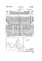
In Figures 1 and 2, I have illustrated a set of dies constructed in accordance with my invention as used in a pressi The press comprises a cross head 32, which operates between uprights 33 and 34. An upper die holder 35 is bolted to head 32 and loosely receives sections 19 and 20 of theupperdie structure' Section 19 is not'mall' i-lieldin raised position in the holder-35 by rods 36, which have their '-'lower ends securedlin section 19,- these rods Y passihg through end flanges 37 of the holder,
which form abutments' forthe lower ends of expansion coilz-springs 38 mounted about the rods and'confined between flanges 37 and zabutment members ingthe form of nuts 39 screwed upon the upper ends of the rods.
Section 'is normally held raised in the holder in a similar manner by rods 40 and springs 41. The two sections '19 and 20 are held against endwise movement through the holder35 by collars 42 mounted for turning movement upon cap screws 43, which are screwed into the die sections from the outer lateral faces thereof, the collars 42 constituting rollers, which bear against the ends mits therelative lateral shifting of the secof the die holder 35. h
. The width of the recess of this holder is somewhat greater than the combined widths of the die sections 19 and 20, these sections being spaced a slight distance apart when the tions toward and away from each. other during. the operation of the dies previously referred to;
A lower bar 44 is secured to the uprights 33 .2 and 34 and extends across the cross head 32 at-theopposite faces thereof. Each of these bars receives two stop members 45 which extend vertically through the bar and have their lower ends disposed torcontact the end portions of die section 19 which projects beyond the ends of the holder 35, as illustrated in Figure 2.- The stop members 45 may conveniently be in the form of bolts which are,
secured in adjustment in the bar 44 by nuts 46 screwing thereon and contacting the upper and lower faces of the bar. Abutment members 47 similar to the members 45 are adjust- 1 ably secured in bars 44, by nuts 48, and are disposed to contact the projecting end portions of die section 20.1 The members 47 extend downwardly a greater distance than the members 45 so that, as the cross head 32 is raised. section 20 contacts the abutment members 47 in advance of contact of section 19 with the members 45. During the continued upward mgvement of the cross head, die section 20 is held against upward movement so as tolbe,i1'1 effect, partially withdrawn from the liolder 35; This serves to open the upper die structure so as to loosen the bar 1 therein.
The'fdie section l9 th en contacts the stops as tojbe held against u ward movement gij-thef remain'der of. t e continued upmovement of the "cross head. Thisis'er'vesto strip the bar.- from pins which may 05 to conform bolt holes in the bar accurately to proper size and spacing. This stripping of the bar from the pins, combined with the preliminary loosenin of the bar by. the opening of the upper ie structure is usually sufficient to cause the bar to drop of its own accord from the upper die, I prefer, however, to provide positive means for stripping the bar from the upper die.
In Figure 2, I have shown the pins for conforming the bolt holes in the bar accurately to size and spacing, as well as knock out pins for stripping the bar from either theupper die or the lower die. I provide round pins 49 and oval pins 50, which I dis pose in alternate relation for enteringthe holes in bar 1, this bar having four holes, as is the commonpractice. The pins 49 and 50 are suitably supported in the die holder 35 and depend therefrom through suitable openings 51, which extendthrough the section 19 of the upper die. These openings 51 are aligned with openings 51 in the lower die 18' as the dies are closed. It will be noted that the openings v51 and 51 are somewhat larger than the pins so as topermit of the shifting of the upper die section 19 previously referred to. The pins act to conform the holes in the bar accurately as to form, size, and spacing during the reforming of the bar.
If the bar adheres to the pins, it is stripped the upper die and during the continued upward movement of the cross head, in the manner previously described. 1
A stripping bar 52 extends through an beyond the opposite faces thereof. The ends of this bar are dis osed to contact the cross bars 54 and 55, which are securedto the uprights 33 and 34 and extend across theopposite faces of the cross head, as the cross'head approaches the limit of its upward movement. This bar carries a knock out pin 56, which extends through aligned openmgs in the cross head and the die holder and die. section 19, the lower end of this pin conta-cting the web of thebar 1 at the center thereof.
- tively stoppin upward movement of bar 52.
The cross head 32 continues its upward movetherefrom after separation of the sections of /.opening 53 in the cross head 32 and projects If the bah does not drop from the upper die ment slightly beyond this point and, during such movement of the cross head,'the pin 56 acts to positively strip bar 1 front the die section 19. I thus provide positive stripping means for removing the bar from the upper die section 19 in the event it adheres to this section after withdrawal of the pins 49 and 50.
The lower die 18 is secured in a die holder 57 by a wedge bar 58. This die holder is secured to bed 59 of the press in a suitable manner, as by means of cap screws 60 which pass through base flanges 61 of the holder 57 and screw into'the press bed 59.
I alsoprovide a knockout pin 62 for the,
'- lower die which operates in a known manner web and the die structure.
to strip the bar there from "when this bar ad- In the modified form of lower die illustrated in Figure5, the die 18 is closed at veach end by a relatively heavy end wall 63.
This wall is provided with two pockets or recesses 64' and 65'.'whichopen into the pass 25 at one side of the blade 17 and the flange passat the other side of the blade, respectively. These pockets or recesses are f of proper depthand size to accommodate tools for planing or dressing the walls of the passes and the blade 17. The passes for the I head of the bar also open into the pocket 65.
In Figure 4, I have illustrated a modified form of mounting the sections of, the upper supported as in Figure 1 and section 20 is supported by bolts 66, which pass loosely through end flanges 37 of the die holder 35. When the holder is in its raised position, section 20 depends from flanges 37 so as to be spaced away from the'base of the holder, as illustrated. As the dies begin to close, the base section 20 is guided into position by the cooperating shoulders 23 and 26 and,
when pressure is applied to the two sections of the upper die structure, these sections act to form the bar, in conjunction with the low er die, in the manner previously described. Upon raising of the upper die structure, the
.By this construction, the base grip of the,
bar is held true until all of the strain of pressure on the bar has been relieved. This is advantageous as assuring accuracy in the base grip of this bar as finally formed.
In Figure 6, I have illustrated a one-piece upper die 67 and a one-piece lowerdie 68. Referring to Figure 7, die 67 is provided with end walls 69, which bridge the ends of pass 70 provided for reception of point 5 of the bar flange, these walls having pockets 71 aligned with the ends of the pass and of a depth to accommodate tools for dressing the walls thereof. End walls 69 are of less vertical thickness than the body of the die, to *fiiYOid interference with proper closing of the dies;- V
The lower die 68, of Figure 6, is provided with -end walls 72 the. upper faces of which In this form, section 19 is are inclined downwardly. from the inner edge of shoulder 26--to the inner corners of the Web contacting projection 73 of such die. These walls bridge the pass 25 and the pass 74 for the heel of the bar. The end walls-72 are provided with pockets 75 and 76 aligned with the ends of the passes 25 and 74, respectively, and of proper depth to accommodate suitable tools for dressing the'walls of these passes. If desired, the end walls 72 may bridge the ends of the head and web passes of die 68, though ordinarily this isnot necessary. Also, under certain conditions, either of the passes 25 or 7 4 may be continued through the end walls, the remaining pass only being bridged by these walls. I also contemplate omitting either of the end walls in either die 67 or upper die'68, if conditions warrant this being done. This also applies to the die of Figure 5, in which either end wall may be omitted. I
The ,bar 11, in Figure 6, is inclined at an angle of several degrees to the horizontal so as to be slightly inclined to the direction of' pressure, as above referred to in discussing Figure 3.- This disposes the base 4 of the bar at an inclination, with the right hand face of blade 17 and the cooperating inner face of die 67 similarly inclined. The die lock 28 is nearly vertical, being but slightly 9 inclined, compared to the die lock 28 of Figure 3. This prevents the application of excessive pressure to base 4 of the rail and, consequently, to blade 17 of the lower die at one side thereof. By boxing the upper die so as to effectively reenforce the thin portion thereof, which is unavoidable due to the necessity of providing a deep pass to accomanodate point 5 of the bar, I am enabled to use a one-piece upper die. When using an upper die of this type, I preferably dispose the bar at an inclination to the horizontal, as in Figure 6, though this is not essential in all cases and the bar may be otherwise disposed to suit special conditions.
I'Vhat I claim is:
rail joint angle bars of the continuous type,
a press comprising a bed and a cross head,
a lower die fixed to the bed and having a bar receiving cavity and an upwardly projecting blade adapted to enter between the base and the flange of the bar, an upper die holder carried by the cross head, an upper die comprising two sections mounted in the holder for relative movement toward and away from each other, means for supporting said sections in the holder for relative vertical movement therein, stops disposed to contactthe sections of the upper die during upward travel thereof with the crosshead, certain of the stops contacting one of the upper die sections in advance of contact of the other steps with the other of said sections, and means for forcing the sections of the upper die toward each in the upward travel thereof with thecross other as the dies are closed under pressure.
' 2. In combination, a press comprising a bed and a cross head, a lower die fixed to the bed and having an upwardly projecting element, an upper die holder carried by the cross head, an upper vdie comprising twotsections mounted in the cross head for relative movement toward and away from each other, means for supporting said sections in the holder for relative vertical movement therein, stops disposed to contact the die sections head, certain of the stops being disposed to contact one of said sections in advance of contact of the other stops with the'other section, and means for forcing the sections of the upper die toward each other as the dies are closed under pressure.
3. In combination, a press comprising a bed and a cross head, a lower die fixed to the bed and having an upwardly projecting element, an upper d'e holder carried by'the' cross head, an upper die comprising two sec- 7 tions mounted in the cross head for relative movement toward and away from each other, means for supporting said sections in the holder for relative vertical movement therein, stops disposed to contact one of the die sections during upwardatravel thereof with the cross head, and means for forcing the sectionslof the upper die toward each other as the dies are closed under pressure. Y
' rail joint bars,- a
' ress com rising a cross head and a bed, a ower 'die, and having an upwardly p rojectingelement,
a die'holder carried by the'cross head, an up, per'die comprising two sections'mounted in' the holder for relative movement" toward-and v away from each other," yielding means norxed to the bed mally holding the die sections in raised posi- I tion in the holder, pins projecting beyondthe lower face of one of said sections 'for conforming the bolt holes in the bar'accurately to size andfspacing, stops disposed to contact the sections of the-upper die during upward travel thereof with the cross head, certain of said stops being disposed to contact theother section of theupper die in advance of contact of the other stops with the pin carrying section, and means for forcing the sections of the upper die te war d each other as the dies are closed under pressure. In witness whereof, I hereunto subscribe my name this 29th da of April 1929.
, GEO GE LAN GFORD.
4. In combination, a press comprising a 4, ed in the cross head for relative movement 6 toward,andfaway from each other, one of said sections having free vertical movement I in the holder independently of the other section, and means for forcing the sections of theupper die toward'each other as thedies are closed under pressure.
5. In combination in means for reformin O rail joint bars, a press comprising a bed and a cross head, a lower die fixed to the bed and having an. upwardly projecting. element, a dieholder carried by the cross head, an upper die comprising two sections mounted in the cross head for relative movement toward and away from each other, one of said sections having free-vertical movement? inthe holder independently of the other section, yielding means normally holdingthe other section raised in the holder, pins projecting beyond the lower face of, said other section .forconforming the bolt holes in the bar accurately to size and spacing, stops disposed to contact the pin carrying section .of the upper die during upward travel thereof with the cross head, and means for'forcing the sections of the upper die toward each other as the dies are closed under pressure.
6. In combination in means for reforming
Priority Applications (1)
| Application Number | Priority Date | Filing Date | Title |
|---|---|---|---|
| US363638A US1804792A (en) | 1929-05-16 | 1929-05-16 | Die |
Applications Claiming Priority (1)
| Application Number | Priority Date | Filing Date | Title |
|---|---|---|---|
| US363638A US1804792A (en) | 1929-05-16 | 1929-05-16 | Die |
Publications (1)
| Publication Number | Publication Date |
|---|---|
| US1804792A true US1804792A (en) | 1931-05-12 |
Family
ID=23431050
Family Applications (1)
| Application Number | Title | Priority Date | Filing Date |
|---|---|---|---|
| US363638A Expired - Lifetime US1804792A (en) | 1929-05-16 | 1929-05-16 | Die |
Country Status (1)
| Country | Link |
|---|---|
| US (1) | US1804792A (en) |
Cited By (2)
| Publication number | Priority date | Publication date | Assignee | Title |
|---|---|---|---|---|
| US2430968A (en) * | 1944-03-17 | 1947-11-18 | Poor & Co | Method and implement for resetting rail anchor jaws |
| US6185978B1 (en) * | 1996-03-18 | 2001-02-13 | Accra Teknik Ab | Method for manufacturing of curved and quenched profiled elements and a die tool for carrying out the method |
-
1929
- 1929-05-16 US US363638A patent/US1804792A/en not_active Expired - Lifetime
Cited By (2)
| Publication number | Priority date | Publication date | Assignee | Title |
|---|---|---|---|---|
| US2430968A (en) * | 1944-03-17 | 1947-11-18 | Poor & Co | Method and implement for resetting rail anchor jaws |
| US6185978B1 (en) * | 1996-03-18 | 2001-02-13 | Accra Teknik Ab | Method for manufacturing of curved and quenched profiled elements and a die tool for carrying out the method |
Similar Documents
| Publication | Publication Date | Title |
|---|---|---|
| US3599318A (en) | Method of bonding sheets | |
| US1804792A (en) | Die | |
| DE2221785C2 (en) | Roller press for compacting, pelletizing or briquetting | |
| US1771028A (en) | Method of corrugating metal boiler sheets | |
| US2050045A (en) | Punch pressing operation | |
| US2066186A (en) | Truing die and method | |
| US1570994A (en) | Spring-forming die | |
| US1932376A (en) | Method of reforming angle splice bars | |
| US1778339A (en) | Die holder | |
| US1306166A (en) | Arpabattjs fob forming sheet metal | |
| US1844700A (en) | Rotary tablet or briquetting machine | |
| US1322116A (en) | Means for forming boiler-headers. | |
| US1201239A (en) | Railroad-rail-rolling mill. | |
| SU412980A1 (en) | STAMP FOR INSTALLATION OF STRAIN HOSE STRIPS | |
| US2261312A (en) | Drop hammer | |
| SU551083A1 (en) | Bending stamp | |
| RU2006328C1 (en) | Stamp for upset of thickenings on rod billets | |
| US1433819A (en) | Jewelry unit and method and apparatus for making the same | |
| US1341721A (en) | Press or stamping-machine | |
| US1452225A (en) | Process of forming curved flanged bars | |
| CN211437686U (en) | Punching type plate and belt sewing machine | |
| US1712506A (en) | Means for reforming worn angle bars | |
| US1857582A (en) | Method of making forged compromise bars | |
| US1649427A (en) | Punch press | |
| US1694862A (en) | Side-seaming press |