US1784112A - Plate holder - Google Patents
Plate holder Download PDFInfo
- Publication number
- US1784112A US1784112A US405189A US40518929A US1784112A US 1784112 A US1784112 A US 1784112A US 405189 A US405189 A US 405189A US 40518929 A US40518929 A US 40518929A US 1784112 A US1784112 A US 1784112A
- Authority
- US
- United States
- Prior art keywords
- sections
- plate
- section
- plate holder
- holder
- Prior art date
- Legal status (The legal status is an assumption and is not a legal conclusion. Google has not performed a legal analysis and makes no representation as to the accuracy of the status listed.)
- Expired - Lifetime
Links
- 210000003813 thumb Anatomy 0.000 description 7
- 210000003811 finger Anatomy 0.000 description 3
- 238000010276 construction Methods 0.000 description 2
- 235000014347 soups Nutrition 0.000 description 2
- 229920002160 Celluloid Polymers 0.000 description 1
- 230000015572 biosynthetic process Effects 0.000 description 1
- 235000019504 cigarettes Nutrition 0.000 description 1
- 238000004519 manufacturing process Methods 0.000 description 1
- 239000000463 material Substances 0.000 description 1
- 230000013011 mating Effects 0.000 description 1
- 239000002184 metal Substances 0.000 description 1
Images
Classifications
-
- A—HUMAN NECESSITIES
- A47—FURNITURE; DOMESTIC ARTICLES OR APPLIANCES; COFFEE MILLS; SPICE MILLS; SUCTION CLEANERS IN GENERAL
- A47J—KITCHEN EQUIPMENT; COFFEE MILLS; SPICE MILLS; APPARATUS FOR MAKING BEVERAGES
- A47J45/00—Devices for fastening or gripping kitchen utensils or crockery
- A47J45/10—Devices for gripping or lifting hot cooking utensils, e.g. pincers, separate pot handles, fabric or like pads
Definitions
- This invention appertains to devices for handling hot plates, pans, and the like.
- One of the primary objects of my invention is to provide a plate holder designed particularly for use in restaurants and hotel kitchens, dining rooms and the like for preventing the thumb of the waiter from coming in contact with the inside margin of the plate or any of its contents and to facilitate the handling in of hot plates as they are taken off of hot racks, out of ovens, and similar places.
- Another important object of my invention is to provide a hot plate holder embodying a pair of hingedly connected sections preferably of an ornamental nature having gripping pads on the inner faces thereof for engaging the opposite faces of a plate, the sections forming an effective hand grip.
- a further important object of my invention is the provision of means for forming a plate holder which will present an attractive appearance and simulate the ordinary construction of a cigarette case, the sections having means for holding the same normally in a closed position when the device is being carried in a pocket.
- a still further object of my invention is to provide an improved hot plate carrier and holder of the above character, which will be :10 durable and efiicient in use, one that will be simple and easy to manufacture, and one which can be placed upon the market at a reasonable cost.
- the invention consists in the novel construction, arrangement, and formation of parts, as will be hereinafter more specifically described,
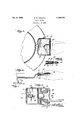
- FIG. 1 is a top plan view of my improved device showing the same in use.
- Figure 2 is a section taken through my improved device on the line 22 of Figure 1 looking in the direction of the arrows showing the companion sections or jaws in their partly opened posit-ion for gripping'a plate.
- Figure 3 is an edge elevation o my improved device showing the same in use and grasping the edge of a soup plate, the soup plate being shown in section.
- Figure 4 is a top plan view of. my improved device showing the sections'in theirextreme open position
- Y Figure 5 is .a detail fra mentary plan view illustrating a modified form of clamp for 66 holding the companion sections in their closed position.
- the letter A generally indicates my improved'plate holder and carrier which comprises a pair of companion sections or grippingmembers.
- These sections can be made of any desired material, but I preferably coni structthe same of metal of such acharacteras to present a pleasing and attractive appearance to the eye.
- the sections 10 and'll are of thesame configuration and each have their marginal ledge bent inwardly to provide sideand end flanges .12. 'The side longitudinal edges of the sections 10 and 11 at one end are preferably rolled to "provide mating hinge barrels which receive a suitable hinge pin or pintle 13. If desired, a coil spring 14 canbe -5.-
- This clasp? 15 can be similar to the ordinary purse clasp,'as shown'in' Figures '1 and 4,- or the same may embody a pivoted latch lfi'hingedly secured to the sectionlO and of-a U-shape in cross section for embrac ing both of the sections 10 and 11 when the sections are in their closed position.
- the r lower section 11 ata central transverse portion has the inner face thereof rovided'with a suitable pad 17 which can be ormed of corrugated rubber.
- the inner face of the section 10 is provided with side pads 18 and 19 which can also be formed of corrugated rubber.
- the sections 10 and 11 are moved to their open position and these sections are grasped between the thumb and fingers of the user and placed over the edge. of the plate.
- Y Pressure can now be brought to bear by the thumb and fingers of the user so as to bring the sections 10 and 11 into engagement with the upperand lower faces of the plates and the pads 17, 18, and 19 will form an efiicient mean-s for gripping the plate and holding the same against slipping.
- the top section 10 at its transverse section can be provided with a struck in recess or cavity 20 for receiving the thumb of the person using the device and this cavity or recess can be lined with celluloid or similar lining 21.
- a hot plate carrier and holder comprising a pair of companion pivotally connected sections, spring means normally urging the sections to an open position, a clasp for holding the sections against swinging movement, and gripping pads carried by the inner faces of said sections.
- a hot plate carrier and holder comprising a pair of companion pivotally connected sections, spring means normally urging the sections to an open position, a clasp for holding the sections against swinging movement, gripping pads carried by the inner faces of said sections, one section having a thumb receiving cavity in its upper face.
- a hot plate carrier and holder comprising a pair of sections, means hingedly connecting the sections together at one longitudi' nal edge, the marginal edges of said sections being provided with inwardly. directed meeting flanges,'spring means normally tending to hold the sections in an opening position, a clasp for holding the sections in a closed position, a transversely extending central corrugated rubber gripping pad carried by the inner face of one section, a pair of inwardly directed side corrugated rubber plate gripping pads carried by the inner face of the other section, and said other section having a thumb receiving cavity in its upper face.
Landscapes
- Engineering & Computer Science (AREA)
- Food Science & Technology (AREA)
- Purses, Travelling Bags, Baskets, Or Suitcases (AREA)
- Table Equipment (AREA)
Description
Dec. 9, 1930. M, R A v 1,784,112
PLATE HOLDER Filed Nov. 6, 1929 INVENTOR. 1 l MAXGZ/YOSA/VO /m mj Patented Dec. 9, 1930 UNITED STATES m e. BOSANO, or cmcaeo, ILLINOIS rLA'rE nonmm Application filed November 6, 1929. Serial No. 40?,189.
This invention appertains to devices for handling hot plates, pans, and the like.
One of the primary objects of my invention is to provide a plate holder designed particularly for use in restaurants and hotel kitchens, dining rooms and the like for preventing the thumb of the waiter from coming in contact with the inside margin of the plate or any of its contents and to facilitate the handling in of hot plates as they are taken off of hot racks, out of ovens, and similar places.
Another important object of my invention is to provide a hot plate holder embodying a pair of hingedly connected sections preferably of an ornamental nature having gripping pads on the inner faces thereof for engaging the opposite faces of a plate, the sections forming an effective hand grip.
A further important object of my invention is the provision of means for forming a plate holder which will present an attractive appearance and simulate the ordinary construction of a cigarette case, the sections having means for holding the same normally in a closed position when the device is being carried in a pocket.
A still further object of my invention is to provide an improved hot plate carrier and holder of the above character, which will be :10 durable and efiicient in use, one that will be simple and easy to manufacture, and one which can be placed upon the market at a reasonable cost.
lVith these and other objects in view, the invention consists in the novel construction, arrangement, and formation of parts, as will be hereinafter more specifically described,
claimed, and illustrated in the accompanying drawings, in which drawings Figure 1 is a top plan view of my improved device showing the same in use.
Figure 2 is a section taken through my improved device on the line 22 of Figure 1 looking in the direction of the arrows showing the companion sections or jaws in their partly opened posit-ion for gripping'a plate.
Figure 3 is an edge elevation o my improved device showing the same in use and grasping the edge of a soup plate, the soup plate being shown in section.
Figure 4 is a top plan view of. my improved device showing the sections'in theirextreme open position, and Y Figure 5 is .a detail fra mentary plan view illustrating a modified form of clamp for 66 holding the companion sections in their closed position. 1
Referring to the drawings in detail, Wherein similar reference characters designate corresponding parts throughout the several 0. views, the letter A generally indicates my improved'plate holder and carrier which comprises a pair of companion sections or grippingmembers. These sections can be made of any desired material, but I preferably coni structthe same of metal of such acharacteras to present a pleasing and attractive appearance to the eye. The sections 10 and'll are of thesame configuration and each have their marginal ledge bent inwardly to provide sideand end flanges .12. 'The side longitudinal edges of the sections 10 and 11 at one end are preferably rolled to "provide mating hinge barrels which receive a suitable hinge pin or pintle 13. If desired, a coil spring 14 canbe -5.-
provided for normally moving the sections to anopen position'when the clasp 15 is released. This clasp? 15 can be similar to the ordinary purse clasp,'as shown'in'Figures '1 and 4,- or the same may embody a pivoted latch lfi'hingedly secured to the sectionlO and of-a U-shape in cross section for embrac ing both of the sections 10 and 11 when the sections are in their closed position. The r lower section 11 ata central transverse portion has the inner face thereof rovided'with a suitable pad 17 which can be ormed of corrugated rubber. The inner face of the section 10 is provided with side pads 18 and 19 which can also be formed of corrugated rubber. Thus when it is desired to grasp a hot plate the sections 10 and 11 are moved to their open position and these sections are grasped between the thumb and fingers of the user and placed over the edge. of the plate. Y Pressure can now be brought to bear by the thumb and fingers of the user so as to bring the sections 10 and 11 into engagement with the upperand lower faces of the plates and the pads 17, 18, and 19 will form an efiicient mean-s for gripping the plate and holding the same against slipping. If preferred the top section 10 at its transverse section can be provided with a struck in recess or cavity 20 for receiving the thumb of the person using the device and this cavity or recess can be lined with celluloid or similar lining 21.
By the use of this device, the hand of the user will be effectively protected from the heat of the plate and likewise the thumb and fingers of the user Will be prevented from coming into contact with the edges of the plate or any of its contents.
Changes in details may be made without departing from the spirit or the scope of this invention, but what I claim as new is:
1. A hot plate carrier and holder comprising a pair of companion pivotally connected sections, spring means normally urging the sections to an open position, a clasp for holding the sections against swinging movement, and gripping pads carried by the inner faces of said sections.
2. A hot plate carrier and holder comprising a pair of companion pivotally connected sections, spring means normally urging the sections to an open position, a clasp for holding the sections against swinging movement, gripping pads carried by the inner faces of said sections, one section having a thumb receiving cavity in its upper face.
3. A hot plate carrier and holder comprising a pair of sections, means hingedly connecting the sections together at one longitudi' nal edge, the marginal edges of said sections being provided with inwardly. directed meeting flanges,'spring means normally tending to hold the sections in an opening position, a clasp for holding the sections in a closed position, a transversely extending central corrugated rubber gripping pad carried by the inner face of one section, a pair of inwardly directed side corrugated rubber plate gripping pads carried by the inner face of the other section, and said other section having a thumb receiving cavity in its upper face.
In testimony whereof I afiix my signature.
MAX G. ROSANO.
Priority Applications (1)
| Application Number | Priority Date | Filing Date | Title |
|---|---|---|---|
| US405189A US1784112A (en) | 1929-11-06 | 1929-11-06 | Plate holder |
Applications Claiming Priority (1)
| Application Number | Priority Date | Filing Date | Title |
|---|---|---|---|
| US405189A US1784112A (en) | 1929-11-06 | 1929-11-06 | Plate holder |
Publications (1)
| Publication Number | Publication Date |
|---|---|
| US1784112A true US1784112A (en) | 1930-12-09 |
Family
ID=23602650
Family Applications (1)
| Application Number | Title | Priority Date | Filing Date |
|---|---|---|---|
| US405189A Expired - Lifetime US1784112A (en) | 1929-11-06 | 1929-11-06 | Plate holder |
Country Status (1)
| Country | Link |
|---|---|
| US (1) | US1784112A (en) |
Cited By (5)
| Publication number | Priority date | Publication date | Assignee | Title |
|---|---|---|---|---|
| US3632151A (en) * | 1969-06-02 | 1972-01-04 | Lawrence F Wosnitzky | Fish-clamping implement |
| US20040227366A1 (en) * | 2003-05-13 | 2004-11-18 | Catherine Dodd | Disposable holder for use with urine specimen cup |
| US20070084025A1 (en) * | 2005-09-29 | 2007-04-19 | Sparks John D | Grasping device with resilient gripping material |
| US20170340171A1 (en) * | 2016-05-30 | 2017-11-30 | Cristel | Removable gripping device for ear-shaped holding member of a kitchen utensil |
| US20240260771A1 (en) * | 2023-02-08 | 2024-08-08 | Yale Mitchell Kadesky | Plate and Bowl Insulator Ring and Method of use |
-
1929
- 1929-11-06 US US405189A patent/US1784112A/en not_active Expired - Lifetime
Cited By (8)
| Publication number | Priority date | Publication date | Assignee | Title |
|---|---|---|---|---|
| US3632151A (en) * | 1969-06-02 | 1972-01-04 | Lawrence F Wosnitzky | Fish-clamping implement |
| US20040227366A1 (en) * | 2003-05-13 | 2004-11-18 | Catherine Dodd | Disposable holder for use with urine specimen cup |
| US7000963B2 (en) | 2003-05-13 | 2006-02-21 | Catherine Dodd | Disposable holder for use with urine specimen cup |
| US20070084025A1 (en) * | 2005-09-29 | 2007-04-19 | Sparks John D | Grasping device with resilient gripping material |
| US20170340171A1 (en) * | 2016-05-30 | 2017-11-30 | Cristel | Removable gripping device for ear-shaped holding member of a kitchen utensil |
| US10743716B2 (en) * | 2016-05-30 | 2020-08-18 | Cristel | Removable gripping device for ear-shaped holding member of a kitchen utensil |
| RU2733705C2 (en) * | 2016-05-30 | 2020-10-06 | Кристель | Removable gripper for ear-shaped holder for kitchen utensils |
| US20240260771A1 (en) * | 2023-02-08 | 2024-08-08 | Yale Mitchell Kadesky | Plate and Bowl Insulator Ring and Method of use |
Similar Documents
| Publication | Publication Date | Title |
|---|---|---|
| US2073280A (en) | Identification bracelet | |
| US2864645A (en) | Tongs | |
| US5901993A (en) | Food handling tongs | |
| US2228726A (en) | Key case | |
| US1355332A (en) | Cooking utensil | |
| US1784112A (en) | Plate holder | |
| US2016356A (en) | Tongs | |
| US2020349A (en) | Culinary utensil | |
| US2031183A (en) | Patty-hoe | |
| US2044661A (en) | Tool chest | |
| US2036645A (en) | Handle means for cases and the like | |
| US2484892A (en) | Chewed gum receptacle | |
| US2420265A (en) | Talisman container | |
| US2228547A (en) | Vessel lifter | |
| US1341371A (en) | Plate-lifter | |
| US2197053A (en) | Clasp for receptacles | |
| US1803218A (en) | Telephone-book holder | |
| US1404669A (en) | Plate or receptacle lifter | |
| US1226367A (en) | Stove-lid lifter. | |
| US1501967A (en) | Dish and plate lifter | |
| US1204682A (en) | Griddle. | |
| US1731598A (en) | Pie rack | |
| US2386284A (en) | Canteen cup | |
| US1588774A (en) | Pan lifter | |
| US1204068A (en) | Cash-purse or tobacco-bag. |