US1777754A - Air-hose coupling - Google Patents
Air-hose coupling Download PDFInfo
- Publication number
- US1777754A US1777754A US23358527A US1777754A US 1777754 A US1777754 A US 1777754A US 23358527 A US23358527 A US 23358527A US 1777754 A US1777754 A US 1777754A
- Authority
- US
- United States
- Prior art keywords
- valve
- lever
- valves
- members
- coupling
- Prior art date
- Legal status (The legal status is an assumption and is not a legal conclusion. Google has not performed a legal analysis and makes no representation as to the accuracy of the status listed.)
- Expired - Lifetime
Links
Images


Classifications
-
- B—PERFORMING OPERATIONS; TRANSPORTING
- B60—VEHICLES IN GENERAL
- B60T—VEHICLE BRAKE CONTROL SYSTEMS OR PARTS THEREOF; BRAKE CONTROL SYSTEMS OR PARTS THEREOF, IN GENERAL; ARRANGEMENT OF BRAKING ELEMENTS ON VEHICLES IN GENERAL; PORTABLE DEVICES FOR PREVENTING UNWANTED MOVEMENT OF VEHICLES; VEHICLE MODIFICATIONS TO FACILITATE COOLING OF BRAKES
- B60T17/00—Component parts, details, or accessories of power brake systems not covered by groups B60T8/00, B60T13/00 or B60T15/00, or presenting other characteristic features
- B60T17/04—Arrangements of piping, valves in the piping, e.g. cut-off valves, couplings or air hoses
- B60T17/043—Brake line couplings, air hoses and stopcocks
-
- F—MECHANICAL ENGINEERING; LIGHTING; HEATING; WEAPONS; BLASTING
- F16—ENGINEERING ELEMENTS AND UNITS; GENERAL MEASURES FOR PRODUCING AND MAINTAINING EFFECTIVE FUNCTIONING OF MACHINES OR INSTALLATIONS; THERMAL INSULATION IN GENERAL
- F16L—PIPES; JOINTS OR FITTINGS FOR PIPES; SUPPORTS FOR PIPES, CABLES OR PROTECTIVE TUBING; MEANS FOR THERMAL INSULATION IN GENERAL
- F16L37/00—Couplings of the quick-acting type
- F16L37/24—Couplings of the quick-acting type in which the connection is made by inserting one member axially into the other and rotating it to a limited extent, e.g. with bayonet action
- F16L37/256—Couplings of the quick-acting type in which the connection is made by inserting one member axially into the other and rotating it to a limited extent, e.g. with bayonet action the coupling not being coaxial with the pipe
-
- Y—GENERAL TAGGING OF NEW TECHNOLOGICAL DEVELOPMENTS; GENERAL TAGGING OF CROSS-SECTIONAL TECHNOLOGIES SPANNING OVER SEVERAL SECTIONS OF THE IPC; TECHNICAL SUBJECTS COVERED BY FORMER USPC CROSS-REFERENCE ART COLLECTIONS [XRACs] AND DIGESTS
- Y10—TECHNICAL SUBJECTS COVERED BY FORMER USPC
- Y10T—TECHNICAL SUBJECTS COVERED BY FORMER US CLASSIFICATION
- Y10T137/00—Fluid handling
- Y10T137/8593—Systems
- Y10T137/87096—Valves with separate, correlated, actuators
- Y10T137/87105—Correlated across separable flow path joint
Definitions
- Myl invention relates toair brake apparatulS fin-11d particularly vto the coupling device used lin :connection with theair hose conneetedywith the train pipes.
- My .improveinents are intendelfor jusein'eonneetion with Y coupling heads or nienibers of the standard type which are coupled and vclamped tof gether' by .
- a rotary movement about a coininen eentregand tliejobject ot my invention is to provide suclrcoupliiig ineinbers with cutoff valves with valve actuating "members manually operatable to close thevalveswith spring actuated locking nieaiis aeting to engage the valve actuatingfineniber when in ⁇ valve open position and?
- said nieans without ⁇ pesitively locking-it and ⁇ a furshver object ofriny invention isv ⁇ torso ⁇ loeate thevalve aCtuatingL-rneansiof each cou- "jplingnieniber, with; reference to afrelatively inovablevledge of the coupled nierriber, that y saidgledge will engageit,actuate toopen .the valve and lock it in valve open position as the members ple witheaeh other; ⁇
- Figure f2 is, a, ⁇ horizontalsectional View of ,thetwoyooiipledlinenibers taken as on the irregulaii'seetion linevQfl-of Figure 3.
- Figure ⁇ 8 isa fr i i berA showing its valve aotuating lever fin valve openposition
- FIG. 1 is va diagrammatic view ushowing l i the valve "actuating lever in valveeloseol posi tion ⁇ andthe then existing position o'iilthe locking device otite own coupling ineniber and the actuating ledge of the A ber.”
- i Figure lOis a sidefelevation'showing the eoupling Vmembers in fully Ycoupled' position.”
- vvalve actuatiiiglever can ingunually "oper ⁇ atedto close theirvalves and i i i
- FigurelQ isa sectional view of al ⁇ iii,odi/,fica- L ⁇ Theeoupling ineinbers indicatedwatA and Aarey similar and similarly equipped/and' ⁇ for thefniostpart they are ofstant afdoenstructio'ii so that theywilloupie with any standard air ⁇ hose Coupling; tliejaii" passages i B have openings B1 equipped with bushings C whichabutas shown in Figs.
- i is thexedseatrfor arotary slide ,valve and ⁇ is shown as .seated von' jay ledge AB2 in ⁇ the 'casting'f ⁇ "H is the"niovablerotary slide i vaiveseatedon seat and eiigagedfwithlthe end of a valve steni ⁇ ],"rotatable ⁇ in ⁇ the bean i ing F1r and having aitapered eiidl'iitting in the tapered seat F3.
- Il indicates a spring, the function of which is to hold the valve I-l against its seat G. As shown in Figs.
- K is a spring actuated locking lever having a downwardly projecting linger KL which engages the lever J when in the position shown in Fig. 8 and locks it in valve open position.
- the lever K is secured to a spindle K2 supported in bearings K3, K, and actuated by a spring K which tends to keep the locking linger in the position shown in Fig. 8.
- the locking linger Kl is so located and formed that when the lever J is moved to the valve closed position, it will rest against it, as shown in Fig. 9, in such a way as to oppose resistance to the movement of the lever to open the valve without positively locking it in valve closed position.
- each valve lever when the two members are coupled together', the lever Ybeing in valve closed position, each valve lever, when the two members are engaged together, as shown in Fig. ll, will lie directly Vin the path of the front edge of the locking ledge D of the coupled memberso that when theY coupling is completed by the rotary movement shown in Fig. 1l, to that shown in Fig. l0, this ⁇ ledge willpress against and move the valve lever to valve opened position, shifting it from the position shown in Fig. 9 to that shown in Fig. 8.
- the movement of the lever raises the finger K1 against the action of the spring K4 and when the valve lever reaches the position shown in Fig. 8, the finger K1L is spring actuated to assume the position shown in' Fig. 8, in which it positively locks the lever J in valve opened position.
- valve spindlez' engages by means of a squared end the cut olf valve, here indicated at 7L and the valve stem is provided with a tapered seat, as indicated at A spring fill is provided to hold the valve h to its seat G.
- the operator rotates the members from the position shown in Fig. l() to that shown in Fig. l1, the ledge I) then assuming the relative position with regard to the valve lever of the coupled member indicated in Fig. 9.
- the operator can then close the valves by first raising the locking lingers Kl Vto to the position shown in dotted lines in Fig. 1l and by then manually shifting the levers J to the position indicated in Fig. 9, thus'closing the valves.
- the closure of the valves brings the ports II1 and Gr1 and Z) into registry, as shown in Fig. 4, so that the air conlined between the cut olf 'valves can escape, thus facilitating the next operation which consists in further rotating the members until they are entirely detached from each other.
- a coupling having the features of claim 2, and in combination therewith spring acV tuatedmanually releasable locking devices located to engage and lockthe valve actuating lever of each member When in valve open position. l e y e 4.
- a coupler having the features of claim 1, in combination with ports formed in the valves and their seats to register when the valves are closed and permit the "escape of air in the coupling.
- ⁇ A coupler having the features of claim e 2, in combination with ports formed in the n valves and their seats toregister ⁇ When the valves are closed and permit theescape of air in the coupling.
Landscapes
- Engineering & Computer Science (AREA)
- General Engineering & Computer Science (AREA)
- Mechanical Engineering (AREA)
- Transportation (AREA)
- Quick-Acting Or Multi-Walled Pipe Joints (AREA)
Description
OGL 7, 1930. KELLER `1,'7'1775754,
AIR HOSE COUPLING Filed Nov. 16 1927 4 Sheets-Sheet m1771930; H, M. KELLER' l 1,777,754
' A11;v HosE GOUPLING i Filed Nov. 16, 1927 4 Sheetsf-Sheet 2 Oct, 7, 1930. H. M. KELLER 1,777,754
`AIR HOSE COUPLING Filed Nov. 16, Y192'7 4 Sheets-Sheet 3 i ,l "l" fbs l n if, I l
Get. 7, 1930.
H; M. KELLER AIR HOSE boUPLING 4 sheets-sheet '4 Filed Nov. 16, 1927 l mem e/LM le llaa,
' Zw/magy 35 'aredetached,roiii'eaeliotlrer.,,il ,l i
.MThe' nature lfoiniy improvements will be i Patented Oct. 1.93
fiiniiliiiinr KELLER,`= or GERMANTOWM `iiiiNNsYINANIA AIR-HOSE COUPLING Application eiezilNovemben 1e,` 1927'.` ,serial No. 2`3`3,5s`5 ,i
"Myl invention relates toair brake apparatulS fin-11d particularly vto the coupling device used lin :connection with theair hose conneetedywith the train pipes. My .improveinents are intendelfor jusein'eonneetion with Y coupling heads or nienibers of the standard type which are coupled and vclamped tof gether' by .a rotary movement about a coininen eentregand tliejobject ot my invention is to provide suclrcoupliiig ineinbers with cutoff valves with valve actuating "members manually operatable to close thevalveswith spring actuated locking nieaiis aeting to engage the valve actuatingfineniber when in `valve open position and? inanuallyreleasable `thereifroni, l said locking Qrneans being preterably adapted tovalso engage the valve ae- #tuatiiig means when in valve closed position Aso `as lto `offer l,resistance:ite the i movement of 3 20. said nieans without `pesitively locking-it and `a furshver object ofriny invention isv `torso `loeate thevalve aCtuatingL-rneansiof each cou- "jplingnieniber, with; reference to afrelatively inovablevledge of the coupled nierriber, that y saidgledge will engageit,actuate toopen .the valve and lock it in valve open position as the members ple witheaeh other;`
i Lfurther objectof inyinvention to vprog vide the eut off valves" and theirseats "withV i ports (which, will registerwith each other `when thevalves,` are `closed and permit the yescape o'f tlieairv held infthe Coupled' iiie1nbers between the valves before saiclineinbers `best understood as.(kscribed` in Connection i ,iywitli the drawings ingvliioir Iliave illustrated urlers i Provided with 1111i impreiemenis Oigandifwill be"` pointed out in theelainis.
i rig-ure 1.1;sapeviewlfiwo coupling i u inenibers provided,withiiny iinprovenients i, shown in fiully eoiipledr position.
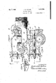
5` Figure f2 is, a,`horizontalsectional View of ,thetwoyooiipledlinenibers taken as on the irregulaii'seetion linevQfl-of Figure 3.
ltion.
are relatively rotated toeouf Figure `is a ver-,tieal A vseeti'inal view` `of ie eotuplingnieiiiber Aoi? Figure 2, 1taken as i" Figure 4 is a section,` taken `on line 4 4 of Figure 5shovviiig a detaill i Figure 5 is face viewofthe out 0H valve in Closed position;v Y i Figure 6, a siinilariview showingthe 4valve open. i ,t f VFigure? isa sectionalelevation online 7-7 `of Figure .1;
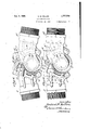
Figure `8 isa fr i i berA showing its valve aotuating lever fin valve openposition;
Figure)` is va diagrammatic view ushowing l i the valve "actuating lever in valveeloseol posi tion `andthe then existing position o'iilthe locking device otite own coupling ineniber and the actuating ledge of the A ber."` i `Figure lOis a sidefelevation'showing the eoupling Vmembers in fully Ycoupled' position." i Figure (is a side elevati'dffshowiiig the Ont elevation of thel iiieni`` members rotated'y to a position in which ,the`
vvalve actuatiiiglever can ingunually "oper` atedto close theirvalves and i i i FigurelQ isa sectional view of al `iii,odi/,fica- L` Theeoupling ineinbers indicatedwatA and Aarey similar and similarly equipped/and' `for thefniostpart they are ofstant afdoenstructio'ii so that theywilloupie with any standard air `hose Coupling; tliejaii" passages i B have openings B1 equipped with bushings C whichabutas shown in Figs. Qand 7 when the `members are'eoupledr- `Each nieinberis `iprovidedwith the standard y eoupliiig ledges` i D" and E ior'ined'to `engage and cani thenieini bers` together when they are-rotated abolita` x A,eoininoncentre." i v, i
the special forni of embodiment ofiny i improvementshownfin the drawings, I forni v each coupling member with la fspindle-ybean ing Ft orined'in i i i i i i i p f aportion of the casting indicated at having, asshowniir Figiire, a stuiiingboxv at one end `indicated at FF? and` i a tapered seat at Athe other i end; `,indicated at F? i is thexedseatrfor arotary slide ,valve and` is shown as .seated von' jay ledge AB2 in `the 'casting'f` "H is the"niovablerotary slide i vaiveseatedon seat and eiigagedfwithlthe end of a valve steni `],"rotatable`in `the bean i ing F1r and having aitapered eiidl'iitting in the tapered seat F3. Il indicates a spring, the function of which is to hold the valve I-l against its seat G. As shown in Figs. 4, 5, and (i, I provide the seat G and valve l-I in addition to their regular ports for opening and closing the air passage, with ports I-l1 and G1, G1 being in registry with the port o in the casing and the ports H1' and G1 being so located that they will register when the cut olf valve is fully closed.
J is a lever secured to the end of the valve spindle I and so located with reference toa ledge of the rib E that, as shown in Figure 8, it will rest against this ledge when in position to hold the valve fully open. The shape of this lever is indicated clearly in Figs. S and 9 and it is movable between the positions shown in Fig. 8 and the position indicated in Fig. l), in which last position the controlled valve is fully closed. rThis valve lever is so shaped and located as to be conveniently operated by hand. K is a spring actuated locking lever having a downwardly projecting linger KL which engages the lever J when in the position shown in Fig. 8 and locks it in valve open position. The lever K is secured to a spindle K2 supported in bearings K3, K, and actuated by a spring K which tends to keep the locking linger in the position shown in Fig. 8. The locking linger Kl is so located and formed that when the lever J is moved to the valve closed position, it will rest against it, as shown in Fig. 9, in such a way as to oppose resistance to the movement of the lever to open the valve without positively locking it in valve closed position.
It will be seen that the lever J is so located and shaped that when the two members are coupled together', the lever Ybeing in valve closed position, each valve lever, when the two members are engaged together, as shown in Fig. ll, will lie directly Vin the path of the front edge of the locking ledge D of the coupled memberso that when theY coupling is completed by the rotary movement shown in Fig. 1l, to that shown in Fig. l0, this` ledge willpress against and move the valve lever to valve opened position, shifting it from the position shown in Fig. 9 to that shown in Fig. 8. The movement of the lever raises the finger K1 against the action of the spring K4 and when the valve lever reaches the position shown in Fig. 8, the finger K1L is spring actuated to assume the position shown in' Fig. 8, in which it positively locks the lever J in valve opened position.
In the modification shown in Fig. l2, the enlarged end of the valve spindlez' engages by means of a squared end the cut olf valve, here indicated at 7L and the valve stem is provided with a tapered seat, as indicated at A spring fill is provided to hold the valve h to its seat G.
In operation we may assume that the Vcut olf valves of two detached coupling members are closed. The operator then partly.
couples the two members, as shown in Fig. ll, and then rotates the coupling members about a common centre to the position shown in Fig. l0. This linal rotary movement of the two members brings the corner of the ledge Dof each member into contact with the lever J of the coupled member and shifts the lever from the position shown in Fig. 9 to that shown in Fig. 8, thus opening the valves which are immediately loclred in open position by the action of the locking linger K1 and it will be seen that even apart from the action of the locking lingers K1 the valve levers J can not be movedfrom valve opened position so long as the coupling members are fully coupled. I thus insure that the cut off valves shall remain open so long as the coupling members are fully coupled.
Then it is desired to uncouple Ithe coupling members, the operator rotates the members from the position shown in Fig. l() to that shown in Fig. l1, the ledge I) then assuming the relative position with regard to the valve lever of the coupled member indicated in Fig. 9. The operator can then close the valves by first raising the locking lingers Kl Vto to the position shown in dotted lines in Fig. 1l and by then manually shifting the levers J to the position indicated in Fig. 9, thus'closing the valves. The closure of the valves brings the ports II1 and Gr1 and Z) into registry, as shown in Fig. 4, so that the air conlined between the cut olf 'valves can escape, thus facilitating the next operation which consists in further rotating the members until they are entirely detached from each other.
' It is an important feature of my 'invention that I provide means, `to wit, the lingers K1, which positively lock the valve lever in valve open position so that in case of the breaking apart of a coupling I avoid the danger of the cut off valves closing since they can only be closed by the manual operation involving the lifting of the locking linger and the manual shifting of the valve lever.
Having now described my invention, what I claim as new and desire to secure by Letters Patent, is:
1. In an air hose coupling the members of which have interengaging ledges whereby they are clamped together when rotated about a common centre in opposite directions, the combination therewith ofl out oli'I valves located .in each member, manually operatable valve actuating means whereby the valves can be opened' and closed when the members arerwholly or partially uncoupled, a ledger on each member located to engage and shift the valve actuating means of the other member to Open its valve when the members are given their rotative motion to clamp them together and to hold the valves open While the members are `fully coupled and spring actuated manuallyfretractable Y locking means on each member located'in lthe `normal path of movement of the valve actuating means and acting automatically to engage and lock the valve actuating means in valve open position. e Y
2. In an air hose coupling the members of Whichhave interengaging ledges Wherel by they are clamped together when rotated about a common centre in opposite direc.- tions7V the combination therewith of rotat-V able slide cut olif valves locatedin each meml ber, means for actuating said valves consist# ing .of a valve spindle extending through the Wall of the member and a manually op- V eratable lever secured to the end of each y spindle, a ledge on each member located to engage the valve actuating lever of vthe coupled member and shift it to open the Valve when the members are `given their rotary motion to clamp them together, said ledges being so located as to permit the manual operation of the `lever to close the valves when the members are rotated to unclamp` Without fully uncoupling them. Y
3. A coupling having the features of claim 2, and in combination therewith spring acV tuatedmanually releasable locking devices located to engage and lockthe valve actuating lever of each member When in valve open position. l e y e 4. A coupler having the features of claim 1, in combination with ports formed in the valves and their seats to register when the valves are closed and permit the "escape of air in the coupling.
5. `A coupler having the features of claim e 2, in combination with ports formed in the n valves and their seats toregister `When the valves are closed and permit theescape of air in the coupling.
HERBERT i M. KELLER Y
Priority Applications (1)
| Application Number | Priority Date | Filing Date | Title |
|---|---|---|---|
| US23358527 US1777754A (en) | 1927-11-16 | 1927-11-16 | Air-hose coupling |
Applications Claiming Priority (1)
| Application Number | Priority Date | Filing Date | Title |
|---|---|---|---|
| US23358527 US1777754A (en) | 1927-11-16 | 1927-11-16 | Air-hose coupling |
Publications (1)
| Publication Number | Publication Date |
|---|---|
| US1777754A true US1777754A (en) | 1930-10-07 |
Family
ID=22877846
Family Applications (1)
| Application Number | Title | Priority Date | Filing Date |
|---|---|---|---|
| US23358527 Expired - Lifetime US1777754A (en) | 1927-11-16 | 1927-11-16 | Air-hose coupling |
Country Status (1)
| Country | Link |
|---|---|
| US (1) | US1777754A (en) |
-
1927
- 1927-11-16 US US23358527 patent/US1777754A/en not_active Expired - Lifetime
Similar Documents
| Publication | Publication Date | Title |
|---|---|---|
| US4125128A (en) | Vented ball-type cut-out cock | |
| US1777754A (en) | Air-hose coupling | |
| US2939674A (en) | Irrigation pipe valve | |
| US1838723A (en) | Valve | |
| US1850457A (en) | Valve | |
| US1279900A (en) | Valve. | |
| US1984828A (en) | Train pipe valve | |
| US1801361A (en) | Valve | |
| US1665913A (en) | Air-brake-release valve | |
| US1655889A (en) | Safety valve | |
| US943554A (en) | Angle-cock. | |
| US1178208A (en) | Three-way valve. | |
| US2460633A (en) | Valve means | |
| US871869A (en) | Means for operating cocks or valves. | |
| US1509816A (en) | Air-brake valve | |
| US1699387A (en) | Operating valve for pressure-operated dump cars | |
| US625783A (en) | Hose-coupling | |
| US1485957A (en) | Valve | |
| US1666478A (en) | Automatic safety angle cock | |
| US810863A (en) | Coupling-section for train air-pipes. | |
| US1569178A (en) | Fluid-pressure indicator | |
| US214336A (en) | Improvement in coupling-valves | |
| US1914457A (en) | Walve for controlling flow of fluid | |
| US717899A (en) | Four-way cock. | |
| US1517325A (en) | Angle cock for air-brake equipment |