US1775813A - Curve cutter - Google Patents
Curve cutter Download PDFInfo
- Publication number
- US1775813A US1775813A US315670A US31567028A US1775813A US 1775813 A US1775813 A US 1775813A US 315670 A US315670 A US 315670A US 31567028 A US31567028 A US 31567028A US 1775813 A US1775813 A US 1775813A
- Authority
- US
- United States
- Prior art keywords
- blade
- handle
- arm
- cutting
- work
- Prior art date
- Legal status (The legal status is an assumption and is not a legal conclusion. Google has not performed a legal analysis and makes no representation as to the accuracy of the status listed.)
- Expired - Lifetime
Links
- 238000005520 cutting process Methods 0.000 description 23
- 239000000463 material Substances 0.000 description 5
- 238000010276 construction Methods 0.000 description 2
- 230000000694 effects Effects 0.000 description 2
- 239000011521 glass Substances 0.000 description 2
- 208000027418 Wounds and injury Diseases 0.000 description 1
- 150000001875 compounds Chemical class 0.000 description 1
- 230000006378 damage Effects 0.000 description 1
- 208000014674 injury Diseases 0.000 description 1
- 230000001788 irregular Effects 0.000 description 1
- 239000002023 wood Substances 0.000 description 1
Images
Classifications
-
- B—PERFORMING OPERATIONS; TRANSPORTING
- B26—HAND CUTTING TOOLS; CUTTING; SEVERING
- B26F—PERFORATING; PUNCHING; CUTTING-OUT; STAMPING-OUT; SEVERING BY MEANS OTHER THAN CUTTING
- B26F1/00—Perforating; Punching; Cutting-out; Stamping-out; Apparatus therefor
- B26F1/38—Cutting-out; Stamping-out
- B26F1/3806—Cutting-out; Stamping-out wherein relative movements of tool head and work during cutting have a component tangential to the work surface
- B26F1/3813—Cutting-out; Stamping-out wherein relative movements of tool head and work during cutting have a component tangential to the work surface wherein the tool head is moved in a plane parallel to the work in a coordinate system fixed with respect to the work
-
- Y—GENERAL TAGGING OF NEW TECHNOLOGICAL DEVELOPMENTS; GENERAL TAGGING OF CROSS-SECTIONAL TECHNOLOGIES SPANNING OVER SEVERAL SECTIONS OF THE IPC; TECHNICAL SUBJECTS COVERED BY FORMER USPC CROSS-REFERENCE ART COLLECTIONS [XRACs] AND DIGESTS
- Y10—TECHNICAL SUBJECTS COVERED BY FORMER USPC
- Y10S—TECHNICAL SUBJECTS COVERED BY FORMER USPC CROSS-REFERENCE ART COLLECTIONS [XRACs] AND DIGESTS
- Y10S30/00—Cutlery
- Y10S30/06—Resilient means
Definitions
- This invention relates to cutting devices, and more particularly to a device for cutting curves of various sorts, particularly compound and irregular curves.
- One of the main objects of my invention is to provide a cutting device of the character stated of simple construction and operation in which the blade is held perpendicular to the work and is supported in such manner as to be readily movable thereover in all directions.
- a further object is to provide means Whereby the blade can be readily adjusted so as to vary its angular relation tothe work and can be renewed when desired at small cost. Further objects and advantages will appear from the detailed description.
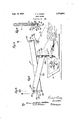
- Fig. l is a perspective View illustrating the manner of using a cutting device constructed in accordance with my invention
- Fig. 2 is a sectional view through the handle, the blade and the holder therefor being shown in elevation;
- Fig. 3 is a section taken substantially on 7 line 33 of Fig. 1;
- v Fig. 4 is a section taken substantially on line 4-4 of Fig. 2.
- this sheet is supported upon a glass plate 2 which rests upon a table 3.
- the provision of the glass plate 2 is not essential but I prefer to utilize this plate as it prevents injury to the cutting edge of the blade such as would be apt to occur if the sheet 1 were supported upon wood or other material of like character into which the blade would enter after cutting through the sheet.
- the cutting device comprises a hand piece or handle 4 bored out from its lower end for reception of a neck 5 which extends upwardly from a head 6, this head being slotted or bifurcated.
- the head and the neck constitute a holder for the cutting blade.
- the upper end of neck 5 is rounded as at 5 and abuts the inner end of the bore which receives this neck, the inner end of this bore being preferably normal to the axis thereof, as illustrated.
- the neck 5 is provided with a circumferential groove 7 which receives the inner end of a retaining screw 8 threaded through handle a.
- the blade holder is thus mounted in handle 4 in such manner as to have free turning movement on the axis of the handle.
- a blade 9 is adjustably and rcmovably secured in head 6 by means of a finger 10 inserted through the slot of this head, and a securing screw 11 threaded into the head transversely of the slot.
- the blade 9 includes the body 12 of rhomboidal shape, finger 10 projecting from the upper inner corner of this body.
- the lower edge 13 of the body is the cutting edge and is inclined downwardly away from the holder, terminating in point 14:.
- This point is disposed eccentric to the holder and is intended and adapted to penetrate the work and to provide a point of contact upon which the blade will readily turn or swivel to accommodate changes in direction thereof along the pattern being cut.
- the downward and outward inclination of the cutting edge 13 relative to the holder is of advantage as producing a draw cut so that relatively thick material can be cut with but little effort.
- a supporting 'alldse'c'uring memberin'the "formfof a screw clamp 15"of known type is Secured to the edge of'table 3.
- my device can be readily attached preferably'ble ofconve'ntional construction, but it will be understood that any other suitable "or'"convenientnevicej for attaching the supporting'rne'ansfto a tablejor like structure can f"be'emplo'yed.
- 'I[-he"inember 15, is provided with a stud '16 projecting vertically from the 'jtop thereof. This stud is disposed perpen- Tdicular'to the upper face of table 3 and, con- 'sequ'ent'ly, to 'the'work 1.
- This'collarpr'ovides means where- I havlng 1 universal connection with the "other "'EOllar'QOatfthelower en'd'of this studf leeve 19 receives shank 21 depending from a yoke 22,which'istransversely slotted from its upe'sh'ank21"'below'yoke 22, by means of a set' g v c 1 1 2.111 adevice of-the 'character described,
- a bearing collar '23 is securedu'pon screw 24, and bears upon fthe'upper end 'of by'thefyoke 22 can'be adjusted vertically "if V Tins-second arm is previded; 'at'its dither desired, and also providesai bearing for the sl1'ank"durin'g turning thereofin sleeve '19.
- second arm "25 is pivot'ally secured, at 26, in yoke 22 and fits's'nugly in the slot of the oke so asto avoid any undesirable loos'eness or thereto, a handle at the otheren'd of the see ond arm and held thereby parallel 'to theaxis 1 Pl yjend, with a sleeve '26 extending transversely "fthere'ot and disposed parallel to sleeves 18 *"and 19' ota'rm '17.
- This-sleeve 26' receives theupp'e'r "portionof handle 4 whichis adjust-,1
- I provide a sleeve 28 of rubber or other suitable material about the lower portion of handle a to facilitate firm holding of the tool-*during use thereof.
- This sleeve "has been omitted in Fig. 2 for the sake of clcarness, In using the device handle 4 is P grasped as irfFig; 1, so as to be held firmly,
- clamp havingan upwardlyprojecting-stud, an arm having parallel sleeves at its ends,
- a handle a holder comprising a slotted head having a neck mounted in the handle for free turning movement, and a cutting blade having a reduced finger extending into the slot of the head and detachably secured therein, said blade being disposed to contact the work at a point eccentric to said neck.
- a handle a holder comprising a slotted head having a neck mounted in the handle for free turning movement, a cutting blade of substantially rhomboidal shape having a reduced finger extending from its upper corner into said slot and disposed substantially parallel to the cutting edge, said blade being so disposed that the point thereof diagonally opposite to said finger contacts the work, and means cooperating with the head for adjustably and releasably securing the finger there-- 1n.
- a handle In a device of the character described, a handle, a holder mounted in the handle for free turning movement, a blade of substantially rhomboidal shape, and means for adjustably securing the blade in the holder with its cutting edge inclined downwardly therefrom toward the work.
Landscapes
- Life Sciences & Earth Sciences (AREA)
- Forests & Forestry (AREA)
- Engineering & Computer Science (AREA)
- Mechanical Engineering (AREA)
- Scissors And Nippers (AREA)
Description
Sept. 16, 1930.' v, v, COLBY 1,775,513
CURVE CUTTER Filed Oct, 29. 1928 [12 venfor -M W 53! M W, Affo ngys Patented Sept. 16, 1930 VINCENT V. COLBY, OF CHICAGO, ILLINOIS CURVE CUTTER Application filed October 29, 1928.
This invention relates to cutting devices, and more particularly to a device for cutting curves of various sorts, particularly compound and irregular curves.
It is possible, by mounting a cutting blade for free turning movement and disposing it to engage the work at a point eccentric to the axis on which the blade turns, to cut curves of various characters. During the cutting operation, the blade, due to its eccentric mounting, trails the supporting member or handle in which such blade is mounted so that the blade may be moved with facility along a line defining a pattern which it is desired to cut. I have found, however, that it is important, to assure accuracy and ease in the cutting operation to support the blade in such manner that it will be disposed perpendicular to the work at all times during the cutting operation.
By thus supporting the blade, itwillreadily turn or swivel so as to follow with ease the curves of intricate patterns and will cut the material or work much more readily than if J the blade were not thus held.
One of the main objects of my invention is to provide a cutting device of the character stated of simple construction and operation in which the blade is held perpendicular to the work and is supported in such manner as to be readily movable thereover in all directions. A further object is to provide means Whereby the blade can be readily adjusted so as to vary its angular relation tothe work and can be renewed when desired at small cost. Further objects and advantages will appear from the detailed description.
In the drawing:
Fig. l is a perspective View illustrating the manner of using a cutting device constructed in accordance with my invention;
Fig. 2 is a sectional view through the handle, the blade and the holder therefor being shown in elevation;
Fig. 3 is a section taken substantially on 7 line 33 of Fig. 1;
v Fig. 4 is a section taken substantially on line 4-4 of Fig. 2.
I have illustrated my invention, in Fig. 1,
Serial No. 315,670.
as used for cutting various designs in a sheet 1 of paper or other material.
Preferably this sheet is supported upon a glass plate 2 which rests upon a table 3. The provision of the glass plate 2 is not essential but I prefer to utilize this plate as it prevents injury to the cutting edge of the blade such as would be apt to occur if the sheet 1 were supported upon wood or other material of like character into which the blade would enter after cutting through the sheet.
The cutting device comprises a hand piece or handle 4 bored out from its lower end for reception of a neck 5 which extends upwardly from a head 6, this head being slotted or bifurcated. The head and the neck constitute a holder for the cutting blade. The upper end of neck 5 is rounded as at 5 and abuts the inner end of the bore which receives this neck, the inner end of this bore being preferably normal to the axis thereof, as illustrated. The neck 5 is provided with a circumferential groove 7 which receives the inner end of a retaining screw 8 threaded through handle a. The blade holder is thus mounted in handle 4 in such manner as to have free turning movement on the axis of the handle.
A blade 9 is adjustably and rcmovably secured in head 6 by means of a finger 10 inserted through the slot of this head, and a securing screw 11 threaded into the head transversely of the slot. The blade 9 includes the body 12 of rhomboidal shape, finger 10 projecting from the upper inner corner of this body.
The lower edge 13 of the body is the cutting edge and is inclined downwardly away from the holder, terminating in point 14:. This point is disposed eccentric to the holder and is intended and adapted to penetrate the work and to provide a point of contact upon which the blade will readily turn or swivel to accommodate changes in direction thereof along the pattern being cut. The downward and outward inclination of the cutting edge 13 relative to the holder is of advantage as producing a draw cut so that relatively thick material can be cut with but little effort. By loosening the screw 11 the angular relation of the blade to the work can be varied so as holder, constituting the cutter,' are held-pen pendicular to the work atall times and are supported in such manner" as to be readily movable thereover in all directions.
A supporting 'alldse'c'uring memberin'the "formfof a screw clamp 15"of known type is Secured to the edge of'table 3. I have found a screw clamp convenient as providing means *wher'eb my device can be readily attached toata'ble ofconve'ntional construction, but it will be understood that any other suitable "or'"convenientnevicej for attaching the supporting'rne'ansfto a tablejor like structure can f"be'emplo'yed. 'I[-he"inember 15,is provided with a stud '16 projecting vertically from the 'jtop thereof. This stud is disposed perpen- Tdicular'to the upper face of table 3 and, con- 'sequ'ent'ly, to 'the'work 1.
*An arm 17 i's pro'vided, at itsends, with sleeves 118 and 19 which are disposed parallel and "extend transversely of 'the'arm, The' "slee've'18 fitssnugly about stud 16 for free tn'rning movement thereonand seats u'oon a sleeve 19. This'collarpr'ovides means where- I havlng 1 universal connection with the "other "'EOllar'QOatfthelower en'd'of this studf leeve 19 receives shank 21 depending from a yoke 22,which'istransversely slotted from its upe'sh'ank21"'below'yoke 22, by means of a set' g v c 1 1 2.111 adevice of-the 'character described,
'perend. A bearing collar '23 is securedu'pon screw 24, and bears upon fthe'upper end 'of by'thefyoke 22 can'be adjusted vertically "if V Tins-second arm is previded; 'at'its dither desired, and also providesai bearing for the sl1'ank"durin'g turning thereofin sleeve '19. A
" second arm "25 is pivot'ally secured, at 26, in yoke 22 and fits's'nugly in the slot of the oke so asto avoid any undesirable loos'eness or thereto, a handle at the otheren'd of the see ond arm and held thereby parallel 'to theaxis 1 Pl yjend, with a sleeve '26 extending transversely "fthere'ot and disposed parallel to sleeves 18 *"and 19' ota'rm '17. This-sleeve 26' receives theupp'e'r "portionof handle 4 whichis adjust-,1
it ably'secured inthi's-sleeve by a set screw 2? j Thef'connection between the arms 17a'nd25 sfin "effect, a universal connection" which "permits movement of arm 25 "about "one axis ""='parallel to' stud-16am about another axis'at.
*ri'ghtan'g'lestoshank 21. Since the arin17 has turningmovement about stud 16, the sup- -portingmeans is QfiSllCh character asto per *mit movement orthe cutter" in all directions over the were "and the combinedlength of To effect this result, I have the arms 17 and 25 is suflicient to permit cut ting of any figure of any size such as would ordinarily be produced by a device of this character. I
Preferably, I provide a sleeve 28 of rubber or other suitable material about the lower portion of handle a to facilitate firm holding of the tool-*during use thereof. This sleeve "has been omitted in Fig. 2 for the sake of clcarness, In using the device handle 4 is P grasped as irfFig; 1, so as to be held firmly,
andis-then moved over the work in such manner as to cause the cuttlng edge of blade 9 to follow accurately'the outline of the design or pattern being cut, as indicated. Due to the tact that'the handle 4 is maintained pe'rpendicu'larl to the work at all times,-*e'ase and accuracy in tracing and cutting the pattern is obtained. V i a g v The blade itseltcan be readily produced at-- "small cost and can be'repla'ced as necessary or desired.
' What I claim is: 5 7 1." In a device otthecharacter described,a
supporting member, an arm pivoted at one end to said membertormovement about an axis'fixed relative thereto, a connecting member pivoted to the other end of the arm on *anaxis fixed relative thereto, the axesofthe "pivotal connections at the ends of the arm'* being parallel, a second arm pivoted atone end to the connecting inemberon an axis per pendicular to the connection between said connecting member and the first arm, a handle carried by the second arm at the other oo end thereof and held thereby paralleltothe axis of theconnection between the first arm and the connecting member, and a cutter-carried by the handle and free to turn about: the axis thereof, said cutter bei g; di pee}. centric-t0 the handle; I
an arm pivoted at one end, a ise'cond arm of the-pivotal mounting of. the first arm; and a cutter carried by thezhandle andiree to turn; on the axis thereof, said cutter being disposed eccentric to the handle.
. M 3. In a device ofthecharacterdescribed, a
clamp havingan upwardlyprojecting-stud, an arm having parallel sleeves at its ends,
one-.of the sleeves receiving said stud and seating upon the clamp, a yoke ha'v-ing '25125 shank mounted in'the' other sleeve, a 'second arm pivoted at one end in'the-yokebnan axis perpendicular'to said'fsha'nk', the 'second arm having at its other endasleeve para'llel.
to the Shank o f y e', & handle 'sec'ured"'130 in the sleeve of the second arm, and a cutting blade carried by the handle for free turning movement on the axis thereof and having a. cutting edge comprising a point eccentric to the handle and adapted to penetrate the work.
4. In a device of the character described, a handle, a holder comprising a slotted head having a neck mounted in the handle for free turning movement, and a cutting blade having a reduced finger extending into the slot of the head and detachably secured therein, said blade being disposed to contact the work at a point eccentric to said neck.
5. In a device of the character described, a handle, a holder comprising a slotted head having a neck mounted in the handle for free turning movement, a cutting blade of substantially rhomboidal shape having a reduced finger extending from its upper corner into said slot and disposed substantially parallel to the cutting edge, said blade being so disposed that the point thereof diagonally opposite to said finger contacts the work, and means cooperating with the head for adjustably and releasably securing the finger there-- 1n.
6. In a device of the character described, a handle, a holder mounted in the handle for free turning movement, a blade of substantially rhomboidal shape, and means for adjustably securing the blade in the holder with its cutting edge inclined downwardly therefrom toward the work.
In witness whereof, I hereunto subscribe my name this 26th day of October, 1928.
VINCENT V. COLBY.
Priority Applications (1)
| Application Number | Priority Date | Filing Date | Title |
|---|---|---|---|
| US315670A US1775813A (en) | 1928-10-29 | 1928-10-29 | Curve cutter |
Applications Claiming Priority (1)
| Application Number | Priority Date | Filing Date | Title |
|---|---|---|---|
| US315670A US1775813A (en) | 1928-10-29 | 1928-10-29 | Curve cutter |
Publications (1)
| Publication Number | Publication Date |
|---|---|
| US1775813A true US1775813A (en) | 1930-09-16 |
Family
ID=23225531
Family Applications (1)
| Application Number | Title | Priority Date | Filing Date |
|---|---|---|---|
| US315670A Expired - Lifetime US1775813A (en) | 1928-10-29 | 1928-10-29 | Curve cutter |
Country Status (1)
| Country | Link |
|---|---|
| US (1) | US1775813A (en) |
Cited By (37)
| Publication number | Priority date | Publication date | Assignee | Title |
|---|---|---|---|---|
| US2485344A (en) * | 1946-08-09 | 1949-10-18 | Abbott Geoffrey Joseph | Machine for slicing potatoes |
| US2495675A (en) * | 1945-11-29 | 1950-01-24 | Porges | Planimeter |
| US2539002A (en) * | 1946-08-09 | 1951-01-23 | Abbott Geoffrey Joseph | Machine for cutting potatoes or other objects into chips or slices |
| US2598443A (en) * | 1947-04-07 | 1952-05-27 | Otto W Roth | Cutting tool |
| US2636266A (en) * | 1949-07-29 | 1953-04-28 | Bert B Sweet | Spoon having a rotatable handle |
| US2639505A (en) * | 1952-03-04 | 1953-05-26 | Ralph E Reynolds | Knife for carving leather and the like |
| US2659143A (en) * | 1951-05-19 | 1953-11-17 | Harvey L Baker | Stencil cutting knife |
| US2735177A (en) * | 1956-02-21 | Engraving instrument used in map | ||
| US2759263A (en) * | 1953-05-04 | 1956-08-21 | Harold E Shigley | Deburring means |
| US2803877A (en) * | 1954-06-01 | 1957-08-27 | Joseph L Belanger | Swivel knife |
| US2966137A (en) * | 1956-11-14 | 1960-12-27 | Chevillon Manuel | Pen point adapter for scribers |
| US3886656A (en) * | 1974-04-11 | 1975-06-03 | Cbs Inc | Swivel knife |
| US3922784A (en) * | 1975-03-03 | 1975-12-02 | Diagravure Film Mfg Corp | Swivel knife for manual operation with blade holder offset skewably from handle |
| US4262419A (en) * | 1979-03-21 | 1981-04-21 | Pierce Donald C | Hand-held cutter for cutting mounting board and the like |
| US4275633A (en) * | 1978-12-13 | 1981-06-30 | Littlehorn Jr John J | Apparatus for producing leaded glass articles |
| US4344230A (en) * | 1978-09-13 | 1982-08-17 | Olander Donald A | Leather tooling apparatus |
| EP0101814A3 (en) * | 1982-07-26 | 1985-04-03 | Gerber Scientific Products, Inc. | Automated sign generator |
| EP0165657A1 (en) * | 1984-03-23 | 1985-12-27 | Alcon Pharmaceuticals Limited | Knife for cataract surgery |
| US4833784A (en) * | 1988-08-04 | 1989-05-30 | Rafael Rivera | Method and apparatus for mechanically marking lottery or other games |
| BE1002009A4 (en) * | 1988-05-26 | 1990-05-15 | B & S Computing B V B A | Cutting appliance for leaf-shaped products |
| EP0349964A3 (en) * | 1988-07-07 | 1991-05-08 | KIMOTO & CO., LTD. | Cutting device for masking film |
| US5045074A (en) * | 1989-05-17 | 1991-09-03 | Board Of Regents, The University Of Texas System | Direct drive blood defibrination apparatus and method |
| USD422188S (en) * | 1999-05-12 | 2000-04-04 | The Antioch Company | Cutter for use with a guiding template |
| WO2000069603A1 (en) * | 1999-05-12 | 2000-11-23 | The Antioch Company | Guided cutting system |
| WO2002076694A1 (en) * | 2001-03-22 | 2002-10-03 | Xyron, Inc. | Cutter guiding means in a substrate cutting apparatus |
| EP1426151A3 (en) * | 1999-12-03 | 2004-07-21 | Bierrebi S.P.A. | An apparatus for cutting pieces of material into appropriate shaped portions |
| US20100289390A1 (en) * | 2009-05-18 | 2010-11-18 | Apple Inc. | Reinforced device housing |
| US20110183580A1 (en) * | 2010-01-25 | 2011-07-28 | Apple Inc. | Apparatus and method for intricate cuts |
| US20110203429A1 (en) * | 2002-07-25 | 2011-08-25 | Christopher Davies | Cutting Device |
| US9011623B2 (en) | 2011-03-03 | 2015-04-21 | Apple Inc. | Composite enclosure |
| US9120272B2 (en) | 2010-07-22 | 2015-09-01 | Apple Inc. | Smooth composite structure |
| US20180193964A1 (en) * | 2015-07-07 | 2018-07-12 | Securo B.V. | Device and method for processing a flexible sheet |
| US10398042B2 (en) | 2010-05-26 | 2019-08-27 | Apple Inc. | Electronic device with an increased flexural rigidity |
| US10407955B2 (en) | 2013-03-13 | 2019-09-10 | Apple Inc. | Stiff fabric |
| US10864686B2 (en) | 2017-09-25 | 2020-12-15 | Apple Inc. | Continuous carbon fiber winding for thin structural ribs |
| US11518138B2 (en) | 2013-12-20 | 2022-12-06 | Apple Inc. | Using woven fibers to increase tensile strength and for securing attachment mechanisms |
| US20230106931A1 (en) * | 2021-10-04 | 2023-04-06 | Slice, Inc. | Swivel blade assembly |
-
1928
- 1928-10-29 US US315670A patent/US1775813A/en not_active Expired - Lifetime
Cited By (46)
| Publication number | Priority date | Publication date | Assignee | Title |
|---|---|---|---|---|
| US2735177A (en) * | 1956-02-21 | Engraving instrument used in map | ||
| US2495675A (en) * | 1945-11-29 | 1950-01-24 | Porges | Planimeter |
| US2485344A (en) * | 1946-08-09 | 1949-10-18 | Abbott Geoffrey Joseph | Machine for slicing potatoes |
| US2539002A (en) * | 1946-08-09 | 1951-01-23 | Abbott Geoffrey Joseph | Machine for cutting potatoes or other objects into chips or slices |
| US2598443A (en) * | 1947-04-07 | 1952-05-27 | Otto W Roth | Cutting tool |
| US2636266A (en) * | 1949-07-29 | 1953-04-28 | Bert B Sweet | Spoon having a rotatable handle |
| US2659143A (en) * | 1951-05-19 | 1953-11-17 | Harvey L Baker | Stencil cutting knife |
| US2639505A (en) * | 1952-03-04 | 1953-05-26 | Ralph E Reynolds | Knife for carving leather and the like |
| US2759263A (en) * | 1953-05-04 | 1956-08-21 | Harold E Shigley | Deburring means |
| US2803877A (en) * | 1954-06-01 | 1957-08-27 | Joseph L Belanger | Swivel knife |
| US2966137A (en) * | 1956-11-14 | 1960-12-27 | Chevillon Manuel | Pen point adapter for scribers |
| US3886656A (en) * | 1974-04-11 | 1975-06-03 | Cbs Inc | Swivel knife |
| US3922784A (en) * | 1975-03-03 | 1975-12-02 | Diagravure Film Mfg Corp | Swivel knife for manual operation with blade holder offset skewably from handle |
| US4344230A (en) * | 1978-09-13 | 1982-08-17 | Olander Donald A | Leather tooling apparatus |
| US4275633A (en) * | 1978-12-13 | 1981-06-30 | Littlehorn Jr John J | Apparatus for producing leaded glass articles |
| US4262419A (en) * | 1979-03-21 | 1981-04-21 | Pierce Donald C | Hand-held cutter for cutting mounting board and the like |
| EP0101814A3 (en) * | 1982-07-26 | 1985-04-03 | Gerber Scientific Products, Inc. | Automated sign generator |
| EP0165657A1 (en) * | 1984-03-23 | 1985-12-27 | Alcon Pharmaceuticals Limited | Knife for cataract surgery |
| BE1002009A4 (en) * | 1988-05-26 | 1990-05-15 | B & S Computing B V B A | Cutting appliance for leaf-shaped products |
| EP0349964A3 (en) * | 1988-07-07 | 1991-05-08 | KIMOTO & CO., LTD. | Cutting device for masking film |
| US4833784A (en) * | 1988-08-04 | 1989-05-30 | Rafael Rivera | Method and apparatus for mechanically marking lottery or other games |
| US5045074A (en) * | 1989-05-17 | 1991-09-03 | Board Of Regents, The University Of Texas System | Direct drive blood defibrination apparatus and method |
| USD422188S (en) * | 1999-05-12 | 2000-04-04 | The Antioch Company | Cutter for use with a guiding template |
| WO2000069603A1 (en) * | 1999-05-12 | 2000-11-23 | The Antioch Company | Guided cutting system |
| US6216577B1 (en) | 1999-05-12 | 2001-04-17 | The Antioch Company | Guided cutting system |
| US6575068B2 (en) | 1999-05-12 | 2003-06-10 | The Antioch Company | Guided cutting system |
| EP1426151A3 (en) * | 1999-12-03 | 2004-07-21 | Bierrebi S.P.A. | An apparatus for cutting pieces of material into appropriate shaped portions |
| EP1426153A3 (en) * | 1999-12-03 | 2004-07-21 | Bierrebi S.P.A. | An apparatus for cutting pieces of material into appropriate shaped portions |
| EP1426152A3 (en) * | 1999-12-03 | 2004-07-21 | Bierrebi S.P.A. | An apparatus for cutting pieces of material into appropriate shaped portions |
| US20060096433A1 (en) * | 1999-12-03 | 2006-05-11 | Bierrebi S.P.A. | Apparatus for cutting pieces of material into appropriate shaped portion |
| WO2002076694A1 (en) * | 2001-03-22 | 2002-10-03 | Xyron, Inc. | Cutter guiding means in a substrate cutting apparatus |
| US20110203429A1 (en) * | 2002-07-25 | 2011-08-25 | Christopher Davies | Cutting Device |
| US8371031B2 (en) * | 2002-07-25 | 2013-02-12 | Belron Hungary Kft-Zug Branch | Cutting device |
| US20100289390A1 (en) * | 2009-05-18 | 2010-11-18 | Apple Inc. | Reinforced device housing |
| US8857128B2 (en) | 2009-05-18 | 2014-10-14 | Apple Inc. | Reinforced device housing |
| US20110183580A1 (en) * | 2010-01-25 | 2011-07-28 | Apple Inc. | Apparatus and method for intricate cuts |
| US8408972B2 (en) * | 2010-01-25 | 2013-04-02 | Apple Inc. | Apparatus and method for intricate cuts |
| US10398042B2 (en) | 2010-05-26 | 2019-08-27 | Apple Inc. | Electronic device with an increased flexural rigidity |
| US9120272B2 (en) | 2010-07-22 | 2015-09-01 | Apple Inc. | Smooth composite structure |
| US9011623B2 (en) | 2011-03-03 | 2015-04-21 | Apple Inc. | Composite enclosure |
| US10407955B2 (en) | 2013-03-13 | 2019-09-10 | Apple Inc. | Stiff fabric |
| US11518138B2 (en) | 2013-12-20 | 2022-12-06 | Apple Inc. | Using woven fibers to increase tensile strength and for securing attachment mechanisms |
| US20180193964A1 (en) * | 2015-07-07 | 2018-07-12 | Securo B.V. | Device and method for processing a flexible sheet |
| US10843301B2 (en) * | 2015-07-07 | 2020-11-24 | Securo B.V. | Device and method for processing a flexible sheet |
| US10864686B2 (en) | 2017-09-25 | 2020-12-15 | Apple Inc. | Continuous carbon fiber winding for thin structural ribs |
| US20230106931A1 (en) * | 2021-10-04 | 2023-04-06 | Slice, Inc. | Swivel blade assembly |
Similar Documents
| Publication | Publication Date | Title |
|---|---|---|
| US1775813A (en) | Curve cutter | |
| US5615488A (en) | Non-slip sewing ruler | |
| US2759503A (en) | Work holding and feeding device for use with table saws | |
| US4265146A (en) | Device for sharpening lawn mower blades | |
| US2255541A (en) | Tool adapter | |
| US4126165A (en) | Wood lathe chisel | |
| US2659143A (en) | Stencil cutting knife | |
| JPS59138407A (en) | Plane | |
| US2371676A (en) | Drill grinding device | |
| US2534490A (en) | Safety razor | |
| US2645259A (en) | Razor blade hand plane | |
| US2066381A (en) | Disk tool | |
| US1923847A (en) | Valve seat cutting device | |
| US1605784A (en) | Instrument-sharpening machine | |
| US4344230A (en) | Leather tooling apparatus | |
| US2458244A (en) | Cutting tool | |
| US1983778A (en) | Combined straight edge and paper trimmer | |
| US2584003A (en) | Grinding wheel profile dressing device | |
| US2197884A (en) | Engraving machine | |
| US1590031A (en) | Cutting tool | |
| JP3223454U (en) | Blade sharpening device | |
| US1584584A (en) | Cutting tool | |
| US1406924A (en) | Guide or gauge for reciprocating hand tools | |
| US1660206A (en) | Scissors sharpener | |
| US4622747A (en) | Cutting device and method for profiling sheet material |