US1771663A - Gun mount - Google Patents
Gun mount Download PDFInfo
- Publication number
- US1771663A US1771663A US357504A US35750429A US1771663A US 1771663 A US1771663 A US 1771663A US 357504 A US357504 A US 357504A US 35750429 A US35750429 A US 35750429A US 1771663 A US1771663 A US 1771663A
- Authority
- US
- United States
- Prior art keywords
- carriage
- gun
- trail
- fork
- gun mount
- Prior art date
- Legal status (The legal status is an assumption and is not a legal conclusion. Google has not performed a legal analysis and makes no representation as to the accuracy of the status listed.)
- Expired - Lifetime
Links
- 238000010276 construction Methods 0.000 description 1
- 230000008878 coupling Effects 0.000 description 1
- 238000010168 coupling process Methods 0.000 description 1
- 238000005859 coupling reaction Methods 0.000 description 1
Images
Classifications
-
- F—MECHANICAL ENGINEERING; LIGHTING; HEATING; WEAPONS; BLASTING
- F41—WEAPONS
- F41A—FUNCTIONAL FEATURES OR DETAILS COMMON TO BOTH SMALLARMS AND ORDNANCE, e.g. CANNONS; MOUNTINGS FOR SMALLARMS OR ORDNANCE
- F41A23/00—Gun mountings, e.g. on vehicles; Disposition of guns on vehicles
- F41A23/28—Wheeled-gun mountings; Endless-track gun mountings
Definitions
- the present invention attains this object; its essential feature being the fact that the gun carriage comprises a front carriage and a back carriage, and that the back carriage with its trail end, together with the upper carriage, cradle and gun, may be rotated around an axis which in general is vertical, the front part of the carriage with its shaft or axis and the wheels remaining at rest.
- the lateral dislacement now comprises a coarse adjustment effected by rotating the trail and a fine adj ustment effected by engaging the direction gear which is arranged between the back carriage and the upper carriage.
- the gun is put on, taken off and carried into the central position of the trail of the carriage.
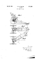
- Fig. 1 shows a side View of the piece of ordnance
- Fig. 2 a plan of the piece of ordnance, the gun and the cradle being removed and the trail being in central position.
- a trail plate 9 are arranged in a known way at the trail end.
- the front and back parts of the gun carriage may be coupled together for transport by a suitable locking device 10.
- a gun mount comprising a rear carriage having a forwardly-extending horizontal fork at its front end; a front carriage straddled by said fork; a wheel-carrying axle journa led horizontally in the front carriage; a
- a gun mount according to claim 1 in which a locking device is provided for coupling the forked part of the rear carriage directly to the front carriage for transport.
- Fig. 3 shows a plan of the piece of ordnance, the trail being in its extreme position to the right.
- 1 is the back part of the gun carriage which, at its front, merges into .a forked end that straddles the front part 2 and is arranged to rotate around the vertical shaft 3.
- the upper carriage 4 On the upper half of the fork the upper carriage 4 is arranged and is connected by means of the upper fork half with the direction gear 5, so as to be rotatable through some degrees.
- the cradle 6 with the gun 7 are mounted as stated above.
Landscapes
- Engineering & Computer Science (AREA)
- General Engineering & Computer Science (AREA)
- Handcart (AREA)
Description
July 29, 1930. K. STRATOMEYER GUN MOUNT Filed April 23. 1929 z vvenlof Xar] flrcziome er Patented July 29, 1930 I UNITED STATES PATENT OFFICE KARL STRATOMEYER, OF THE HAGUE, NETHERLANDS, ASSIGNUR TO NAAMLOOZE VENNOOTSOHAP: HOLLANDSCI-IEINDUSTRIE- EN HANDELMAATSCHAPPIJ, OF THE HAGUE, NETHERLANDS GUN MOUNT Application filed April 23, 1929, Serial No.
For modern wheeled gun carriages in gen eral a large range of direction is required. This requirement has been fulfilled heretofore by the so-called spread carriage, i. e., a carriage with divided trail, or by the use of a platform on which the carriage may be rotated. The disadvantages of these constructions are known. The desirability of a simple wheeled gun carriage which enables a large range of direction to be obtained without the use of a platform or without division of the trail, has often been stated, particularly by military authorities.
The present invention attains this object; its essential feature being the fact that the gun carriage comprises a front carriage and a back carriage, and that the back carriage with its trail end, together with the upper carriage, cradle and gun, may be rotated around an axis which in general is vertical, the front part of the carriage with its shaft or axis and the wheels remaining at rest. The lateral dislacement now comprises a coarse adjustment effected by rotating the trail and a fine adj ustment effected by engaging the direction gear which is arranged between the back carriage and the upper carriage. The gun is put on, taken off and carried into the central position of the trail of the carriage.
The invention is illustrated in the accompanying drawing in which f Fig. 1 shows a side View of the piece of ordnance, and
Fig. 2 a plan of the piece of ordnance, the gun and the cradle being removed and the trail being in central position.
357,504, and in Germany October 1, 1927.
a trail plate 9 are arranged in a known way at the trail end. The front and back parts of the gun carriage may be coupled together for transport by a suitable locking device 10.
I claim l. A gun mount, comprising a rear carriage having a forwardly-extending horizontal fork at its front end; a front carriage straddled by said fork; a wheel-carrying axle journa led horizontally in the front carriage; a
vertical shaft extending through the fork and the front carriage and around which said fork is designed to rotate relativelyto said front carriage and said axleand its wheels; an upper carriage mounted on the upper member of the fork and provided with trunnion bearings; a gun cradle journaled in said bearings; a gun mounted in said cradle; and a direction gear connecting the upper carriage with the said upper fork member to swing the rear carriage and the parts mounted thereon about said shaft and relatively to the front carriage, axle and wheels which remain sta-' ti-onary during such swinging movement.
2. A gun mount according to claim 1, in which a locking device is provided for coupling the forked part of the rear carriage directly to the front carriage for transport.
In testimony whereof I affix my signature. KARL STRATOMEYER.
Fig. 3 shows a plan of the piece of ordnance, the trail being in its extreme position to the right.
In the drawing, 1 is the back part of the gun carriage which, at its front, merges into .a forked end that straddles the front part 2 and is arranged to rotate around the vertical shaft 3. 7 On the upper half of the fork the upper carriage 4 is arranged and is connected by means of the upper fork half with the direction gear 5, so as to be rotatable through some degrees. In the trunnion bearings of the upper carriage the cradle 6 with the gun 7 are mounted as stated above. A spade 8 and
Applications Claiming Priority (1)
| Application Number | Priority Date | Filing Date | Title |
|---|---|---|---|
| DE1771663X | 1927-10-01 |
Publications (1)
| Publication Number | Publication Date |
|---|---|
| US1771663A true US1771663A (en) | 1930-07-29 |
Family
ID=7742595
Family Applications (1)
| Application Number | Title | Priority Date | Filing Date |
|---|---|---|---|
| US357504A Expired - Lifetime US1771663A (en) | 1927-10-01 | 1929-04-23 | Gun mount |
Country Status (1)
| Country | Link |
|---|---|
| US (1) | US1771663A (en) |
-
1929
- 1929-04-23 US US357504A patent/US1771663A/en not_active Expired - Lifetime
Similar Documents
| Publication | Publication Date | Title |
|---|---|---|
| US1771663A (en) | Gun mount | |
| US2382989A (en) | Attachment for hand trucks | |
| US2247725A (en) | Tractor | |
| US1504504A (en) | Ordnance | |
| US2479457A (en) | Child's play wagon | |
| US3009395A (en) | Field piece with swingably mounted wheels | |
| US2039198A (en) | Gun carriage | |
| US1657009A (en) | Mount for guns | |
| US2494482A (en) | Steerable and full swiveling tail wheel | |
| GB761708A (en) | Improvements in and relating to carriages for guns and the like | |
| GB191218679A (en) | Improvements in or relating to Gun Carriages. | |
| US1424105A (en) | Betractihg mechanism | |
| GB515778A (en) | A tram-road system for road vehicles and road trains | |
| US1029303A (en) | Gun to be mounted upon automobiles. | |
| GB191508426A (en) | An Improved Carriage for a Central Pivot Gun. | |
| US1138949A (en) | Wheeled gun-carriage. | |
| US1360549A (en) | Gun with railway gun-carriage | |
| US1970560A (en) | Gun carriage | |
| US1606116A (en) | Mount for wheeled gun carriages | |
| US539944A (en) | Herman jakobsson | |
| US1858935A (en) | Axle bearing | |
| US2547580A (en) | Vehicle body and running gear support | |
| DE549656C (en) | Single wheel drive for electrically operated track vehicles with continuous non-rotating car axles | |
| US1598675A (en) | Trailer having four steering wheels | |
| US833636A (en) | Trail for the carriages of guns mounted on wheels. |