US1764591A - Brake device for laying electrical open-air lines, cables, and the like - Google Patents
Brake device for laying electrical open-air lines, cables, and the like Download PDFInfo
- Publication number
- US1764591A US1764591A US253376A US25337628A US1764591A US 1764591 A US1764591 A US 1764591A US 253376 A US253376 A US 253376A US 25337628 A US25337628 A US 25337628A US 1764591 A US1764591 A US 1764591A
- Authority
- US
- United States
- Prior art keywords
- line
- drum
- cables
- brake
- air lines
- Prior art date
- Legal status (The legal status is an assumption and is not a legal conclusion. Google has not performed a legal analysis and makes no representation as to the accuracy of the status listed.)
- Expired - Lifetime
Links
Images

Classifications
-
- B—PERFORMING OPERATIONS; TRANSPORTING
- B66—HOISTING; LIFTING; HAULING
- B66D—CAPSTANS; WINCHES; TACKLES, e.g. PULLEY BLOCKS; HOISTS
- B66D5/00—Braking or detent devices characterised by application to lifting or hoisting gear, e.g. for controlling the lowering of loads
-
- B—PERFORMING OPERATIONS; TRANSPORTING
- B66—HOISTING; LIFTING; HAULING
- B66D—CAPSTANS; WINCHES; TACKLES, e.g. PULLEY BLOCKS; HOISTS
- B66D2700/00—Capstans, winches or hoists
- B66D2700/03—Mechanisms with latches or braking devices in general for capstans, hoists or similar devices as well as braking devices actuated electrically or by fluid under pressure
Definitions
- This invention relates to a brake-device for laying electrical open air lines, cables and the like. i fIn'the laying of electrical open air lines it has been found to be of advantage, that the line to be stretched does not touch the soil. It is therefore usual to arrange a brake between the line winch drawing the line over the fields and the line drum from which,
- the line is unwound, said brake stretching the piece of'line between the winch and the 7 drum.
- the line is running in several windings around two drums provided with-corresponding grooves, both drums being subjected to braking action.
- a cheek brake In 'order that the necessary friction maybe safely. obtained, when the lines are going over both these drurnsl,it is usual to arrange a cheek brake before the drums for a stretchingjof the line.
- This de- 7 vice has, however, the disadvantage, that the form and surfaceof the lineinay be varied by the cheek brake. It is also nearlyirnpos sible, to brake both the'line drums uniformly; When the braking action is, however,
- the drum is constructed in such a mannerthat its" diameter decreases from the upwinding'to the unwinding side. 7
- the tensionof' the line upon the. drum cannot '4 0 be released; 'At that place where the line coming fromthe line drum is'woundnp upon the brake drum their also be a guide, which has, however, to effectno'or no essential brakeactiom r I g
- the new device is'illus'trated in the an nexed drawings byway of example.
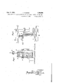
- the invention is howev'eiynot' limited to this ample, but may be widely varied in construe tional features, without deviating from the etae reana inGerniany December 21, 192 3 t Ks I :Figi '1 isga longitudinal section whole device, 2 v a vFig. ,2 la viewfsuponzthe guide with the frame inisection and 7' I :Eig. :3 a horizontal section :through the brake druniandwthe guide. i
- '9 is a iguide for'i the line ⁇ unwinding ifroni the. drum.
- the carriage l isprovidedwith hooks 1O forxpositioning it byanchoi-ing. :11.
- r The ends of the brake band Ta're zprm vided wiwith llugs "l2 ithrough "which the threaded bolt 15 passes, one end-of the bolt- 15 Sbeing mounted upon an ⁇ axle 1'3 and the 1 cylindrical but preferably is: slightly conical v with'its smaller diaineteraat the eunw-inding sided This slightly ie'onical form vdacilitates the. lateral shifting of cable 4L towards ⁇ the unwinding s'idefo'ifl fitheihrake drum 2, and: opposes thev accidental shifting of the cable in the opposite direction, thus preventing slippage of the cable upon unwinding tension.
- the line 4 is drawn I reduction of the The guide wards thefunwindin'g side In ordertoavoid a deformation of the line by thefcoinpara; s
- the guide 6 is'prefe'rably 6 effects theaxial inovenient" of the line windings upon the' drurn :2 toprovided with profilesas shown in Figfi-B,
- the guide "6 itself is guided byside flanges 18 of the druni 2. l
- the energy necessary for inovingjthe windings sidewards is taken up theguide 5v andthe drum 2 without being transmitted to the-frame work lfiof I the carriage 1.
- a second guideS is arranged, at theunwindingsideof the drum 2 and con struetedihsiicha manner that it may Ifoli i low the movements of the line and has an equalizing-effect upon the line by restoring its desired round cross section, in case the line should have been deformed by the brak ing action.
- the brake' is constructed in such a manner, that no action takes place upon the axis. band 7 are taken up by axle 13 and transferred to the framework 16.
- the braking action may be regulated in the usual way by means of hand wheel 14. r
- the carriage maybe anchored in the usual manner for example by hooks 10 and cable 11. 7 7
- a braking deviceior laying electrical lines and cable the combination with a smooth-surfaced brake drum of conical form, the diameter decreasing slightly towards the unwinding side, and adjustable means for frictionally opposing the rotation of said drum, of a guide having a helically grooved surface adjacent the face of said drum, the line being wound on said drum and with a portion of each of a plurality of turns seated in the respective grooves of said guide, and guides for directing the line to and from the brake drum.
Description
June 17, 1930. J. ZAGORSKL 1,764,591
BRAKE DEVICE FOR LAYING ELECTRICAL OPEN AIR LINES, CABLES, AND THE LIKE Filed Feb. 10. 1928 2 Sheets-Sheet 1 June 17, 1930'. J. zAeoRskl 1,764,591
BRAKE DEVICE FOR LAYING ELECTRICAL'OPEN AIR LINES, CABLES, AND THE LIKE In venfqr:
5. scope of the invention.
Patented dune 17, 193% Joz-rArnv zaeonsrti, or FnaNKFonT-oN-Tnanrarn Application filed February 10,1928, Serial No.
This invention relates to a brake-device for laying electrical open air lines, cables and the like. i fIn'the laying of electrical open air lines it has been found to be of advantage, that the line to be stretched does not touch the soil. It is therefore usual to arrange a brake between the line winch drawing the line over the fields and the line drum from which,
1 the line is unwound, said brake stretching the piece of'line between the winch and the 7 drum. In the brakes known for this purpose the line is running in several windings around two drums provided with-corresponding grooves, both drums being subjected to braking action. In 'order that the necessary friction maybe safely. obtained, when the lines are going over both these drurnsl,it is usual to arrange a cheek brake before the drums for a stretchingjof the line. This de- 7 vice has, however, the disadvantage, that the form and surfaceof the lineinay be varied by the cheek brake. It is also nearlyirnpos sible, to brake both the'line drums uniformly; When the braking action is, however,
not uniform theline n ayeasilyslip over the I brakingdevice. v These disadvantages areavoid'edaccording to theinvention whichconsists in using as the brake a single drum smooth-surfaced around whichthe line goes in several windings. The drum is provided with a guide for the line, by which the line windings are moved fromthe upwinding to the unwinding I side of the'dru n. V In'order to secure'a good,
brakeaction, the drum is constructed in such a mannerthat its" diameter decreases from the upwinding'to the unwinding side. 7 Thus the tensionof' the line upon the. drum cannot '4 0 be released; 'At that place where the line coming fromthe line drum is'woundnp upon the brake drum their also be a guide, which has, however, to effectno'or no essential brakeactiom r I g The new device is'illus'trated in the an nexed drawings byway of example. The inventionis howev'eiynot' limited to this ample, but may be widely varied in construe tional features, without deviating from the etae reana inGerniany December 21, 192 3 t Ks I :Figi '1 isga longitudinal section whole device, 2 v a vFig. ,2 la viewfsuponzthe guide with the frame inisection and 7' I :Eig. :3 a horizontal section :through the brake druniandwthe guide. i
- ZUpOn 1a carriage'l is arranged the brake drum 2"rotating around the axis 7 3. The line 4 runs through a gu'idefi and :is passed sev eral; itimes cir'cumferentially about @ifile rsmoothesurfaced i'dlll'm' ;2.- Thegiiide 6 is 'sli'dably mountedIon'bolts'r8aof the carriage frame,- =thus 7 making it easily exchangeable.
'9 is a iguide for'i the line {unwinding ifroni the. drum. I The carriage l isprovidedwith hooks 1O forxpositioning it byanchoi-ing. :11. r The ends of the brake band Ta're zprm vided wiwith llugs "l2 ithrough "which the threaded bolt 15 passes, one end-of the bolt- 15 Sbeing mounted upon an {axle 1'3 and the 1 cylindrical but preferably is: slightly conical v with'its smaller diaineteraat the eunw-inding sided This slightly ie'onical form vdacilitates the. lateral shifting of cable 4L towards {the unwinding s'idefo'ifl fitheihrake drum 2, and: opposes thev accidental shifting of the cable in the opposite direction, thus preventing slippage of the cable upon unwinding tension.
The line 4 is drawn I reduction of the The guide wards thefunwindin'g side In ordertoavoid a deformation of the line by thefcoinpara; s
tively great forces necessary for inovii1g.,the
windings sidewards the guide 6 is'prefe'rably 6 effects theaxial inovenient" of the line windings upon the' drurn :2 toprovided with profilesas shown in Figfi-B, The guide "6 itself is guided byside flanges 18 of the druni 2. l Thus'the energy necessary for inovingjthe windings sidewards is taken up theguide 5v andthe drum 2 without being transmitted to the-frame work lfiof I the carriage 1. A second guideS) is arranged, at theunwindingsideof the drum 2 and con struetedihsiicha manner that it may Ifoli i low the movements of the line and has an equalizing-effect upon the line by restoring its desired round cross section, in case the line should have been deformed by the brak ing action. The brake'is constructed in such a manner, that no action takes place upon the axis. band 7 are taken up by axle 13 and transferred to the framework 16. The braking action may be regulated in the usual way by means of hand wheel 14. r
v The carriage maybe anchored in the usual manner for example by hooks 10 and cable 11. 7 7
I claim: 7
1. In a braking deviceior laying electrical lines and cable, the combination with a smooth-surfaced brake drum of conical form, the diameter decreasing slightly towards the unwinding side, and adjustable means for frictionally opposing the rotation of said drum, of a guide having a helically grooved surface adjacent the face of said drum, the line being wound on said drum and with a portion of each of a plurality of turns seated in the respective grooves of said guide, and guides for directing the line to and from the brake drum.
2. The invention as set forth in'claim 1, wherein the said drum is provided with end flanges against which said helically grooved guide is seated. V
3. The invention as set forth in claim 1,
wherein the guide for directing the line.
from the drum is provided with an aperture corresponding to the cross-section of the line, whereby any deformation of the line due to the braking action is corrected as the line leaves the drum. 7 7
In testimonywhereof I aflix my signature. r V
J OHANN ZAGQRSKI.
The circumferential stresses on
Applications Claiming Priority (1)
| Application Number | Priority Date | Filing Date | Title |
|---|---|---|---|
| DE1764591X | 1926-12-21 |
Publications (1)
| Publication Number | Publication Date |
|---|---|
| US1764591A true US1764591A (en) | 1930-06-17 |
Family
ID=7742298
Family Applications (1)
| Application Number | Title | Priority Date | Filing Date |
|---|---|---|---|
| US253376A Expired - Lifetime US1764591A (en) | 1926-12-21 | 1928-02-10 | Brake device for laying electrical open-air lines, cables, and the like |
Country Status (1)
| Country | Link |
|---|---|
| US (1) | US1764591A (en) |
-
1928
- 1928-02-10 US US253376A patent/US1764591A/en not_active Expired - Lifetime
Similar Documents
| Publication | Publication Date | Title |
|---|---|---|
| US1973446A (en) | Cable guiding device | |
| US3526570A (en) | Parallel wire strand | |
| US2811322A (en) | Cable winding clamping apparatus | |
| US2732150A (en) | Balanced cable spooling | |
| US1764591A (en) | Brake device for laying electrical open-air lines, cables, and the like | |
| US3659633A (en) | Method of making parallel wire strand | |
| US3076618A (en) | Wound material tensioning device | |
| US2389878A (en) | Strand engaging drum | |
| US2947494A (en) | Apparatus for paying out and winding in cables, wires, ropes and the like | |
| US2738938A (en) | Level wind attachment for winches | |
| DE1083972B (en) | Cords, lines, ropes or the like made from fully synthetic threads | |
| US3292873A (en) | Winches for paying out cables | |
| US2555501A (en) | Pulley winch | |
| RU2690312C1 (en) | Winch cable layer | |
| US1935975A (en) | Safety appliance for rotary winding members of hauling machines | |
| GB1576339A (en) | Manufacture of elongate optical fibre waveguide structures | |
| DE864965C (en) | Braking device for coils | |
| EP2980003B1 (en) | Winch with a cable guiding device | |
| SU700578A1 (en) | Device for levelling-out the tension of wound elements, as attachment to rope-winding machine | |
| DE622295C (en) | Device for winding up wires, threads, cables or similar winding material | |
| CN114132858A (en) | Steel wire rope pre-tightening and winding auxiliary device for tower crane | |
| DE47478C (en) | Cable drum with independently rotatable grooved rings | |
| DE553603C (en) | Method and device for regulating the warp thread tension on ribbon and wide looms | |
| US3596737A (en) | Braking apparatus | |
| DE519644C (en) | Braking device for laying electrical lines, cables, etc. like |