US1762898A - Water still - Google Patents
Water still Download PDFInfo
- Publication number
- US1762898A US1762898A US192983A US19298327A US1762898A US 1762898 A US1762898 A US 1762898A US 192983 A US192983 A US 192983A US 19298327 A US19298327 A US 19298327A US 1762898 A US1762898 A US 1762898A
- Authority
- US
- United States
- Prior art keywords
- boiler
- condenser
- water
- pipe
- still
- Prior art date
- Legal status (The legal status is an assumption and is not a legal conclusion. Google has not performed a legal analysis and makes no representation as to the accuracy of the status listed.)
- Expired - Lifetime
Links
Images
Classifications
-
- C—CHEMISTRY; METALLURGY
- C02—TREATMENT OF WATER, WASTE WATER, SEWAGE, OR SLUDGE
- C02F—TREATMENT OF WATER, WASTE WATER, SEWAGE, OR SLUDGE
- C02F1/00—Treatment of water, waste water, or sewage
- C02F1/02—Treatment of water, waste water, or sewage by heating
- C02F1/04—Treatment of water, waste water, or sewage by heating by distillation or evaporation
-
- Y—GENERAL TAGGING OF NEW TECHNOLOGICAL DEVELOPMENTS; GENERAL TAGGING OF CROSS-SECTIONAL TECHNOLOGIES SPANNING OVER SEVERAL SECTIONS OF THE IPC; TECHNICAL SUBJECTS COVERED BY FORMER USPC CROSS-REFERENCE ART COLLECTIONS [XRACs] AND DIGESTS
- Y10—TECHNICAL SUBJECTS COVERED BY FORMER USPC
- Y10S—TECHNICAL SUBJECTS COVERED BY FORMER USPC CROSS-REFERENCE ART COLLECTIONS [XRACs] AND DIGESTS
- Y10S203/00—Distillation: processes, separatory
- Y10S203/18—Control
Definitions
- Another principal object of the invention is to provide stills which are compact, inex- '-pen'sive to manufacture, and having safety features tendingito keep the stills in good condition for a great length of time and miniac mizin'g dangers to 't-heoperators'or those'in the vicinity of the stills.
- Another obj ect of the invention is to provide stills that areecono'mical in operation and. this is partly accomplished by the disposition ofthe various compartments, such as of the storage tank, condenser, and boiler,
- a further object of the invention to pro vide a still including a boiler so arranged that access can be readily gained to the interior thereof for the removal of accumulations of foreign matter.
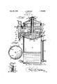
- Figure 1 is a central vertical sectional view thru a still constructedaccording to my in- Figure '2 'isa cross sectional viewjonaireduced scale thru the'main bodyportion of the stilLsubs'ta ntialIy on theline 2+2 o'f- Figurel. e.
- Figure 3 is an enlarged fragmentarysectional view thruan upper portion of the t l h wing a Water seal hich I have fonnd I desirable as apart of same.-
- A designates the main bodyofthe still, preferably of columnar or" stack form and may be either round,. oval,
- boiler prefera bly disposed uppermost inorlj z i v with respect to the body A; C a condenser preferablyxdisposed below boiler B-in the body A; Dja' watery distributor. associatedwith the boiler B and condenser'G; E a pipe afiording' a way for air andvaporfromethe j interior of the body A to the-atmosphere at the top of the still, as chm a vent cap F and G a safety device associated'with the boiler B,
- Afit preferably comprises a lower section 4 prolin'g a compartments f t distilled water, and an upper section 6 joined tothe lower section as" by crimping the up atth'e lower portion of the upper section. Adjacent thebottom9 of section it there may bexprovided'a drain cock 10 and in order to enable a'person tov readily determines the quantity of "condensed waterj stored incompartment 15, a water gauge 11 may be provided in connectionfw'ith lower .seotionj4.
- the upper section 6 may beprovided with ahead 12 at its" upperend strengthen and give finish to this section ⁇ p l n
- the boiler-B i's suspended, so to speak, in the main body, by havin'gits upper portion welded, orotherwise ,9 secured to the mainbo'dylas'at 14 there being v preferably provided a water seal 15 between i a lid '16 and the main body portion of the boiler.
- the lid16i is, friisto-co'nicaf in shape"and provi'ded with a v flange 1'? which extends downwardly into an annular recess 18 formed by a channel shaped flange 19 extending exteriorly about the Wall 13.
- the arrangement is for steam as a heating medium conducted thru a coil 20 in the boiler B, with an entrance as at 21 and an exit as at 22, this coil being disposed in close proximity to the bottom 23 of the boiler, which bottom is preferably cone-like in shape, or frusto-conical in the example shown, with a pipe or tube'24 extending upwardly from an opening 25in thebottom 23,
- this pipe ortuhe providing a steam passage other heating mediums maybe used, such as gas, electricity, etc., and its capacity proportionately changed for economical use of the heating medium.
- the space 26 between the wall 13 of the boiler and the wall of the main body may be materially increased. Also the boiler may be supported in the upper portion of the main body in anysuitable manner.
- the condenser 'C is of novel formation and preferably includes a cone-like top wall 27 an invertedvcone-likebottom wall 28, a frustoconical bafile plate 29 associated with the bottom. wall 28, and means, such as tubes 30 affording passageways for steam, vapor, and products of condensation from the space between the top wall 27 and bottom wall 23 of the boiler, to the space between the bottom wall 28 ofthecondenser and the battle plate. 29, which latter serveseto restrict the steam, vapor, and products of condensation to a path in close proximityto the bottom wall 28.
- the walls 27 and 28 are preferably frusto-conical in shape, and relatively thin so as to readily conduct cold of thecooling medium which is circulated between these walls, to the space adjacent the walls at the exterior of thecondenser.
- the topand bottom walls 27 and 28 may be joined together at the central portion, by the pipe E which is secured to the walls and extends upwardly thru the pipe or tube24, thru the boiler and afiords a passageway 31 for air and vapor'from the compartment 5 to the atmosphere at the upper portion of the still.
- the upper portion of pipe E may carry a screw threaded sleeve 32 serving to support,
- the lid 16, and 7 also a vent cap F, which latter comprises a screw threaded sleeve 35 having transverse passageWays 36, and a conical head 37
- a vent cap F which latter comprises a screw threaded sleeve 35 having transverse passageWays 36, and a conical head 37
- the cooling medium for the condenser such as water
- the cooling medium for the condenser may be introduced as thru pipe 38 extending thru the wall of main body A, and the water may find exit from the condenser as by pipe 39 having a bend 40, so as to dispose the intake 41 of pipe 39. adjacent the upper inner face of wall. 27, thus. compelhng the water to circulate between the walls 27 and 28 before finding egress from the condenser.
- the water distributor D preferably includes a column 42, for water, disposed alongside the main body A, and having a drain cook 43 at its lower portion. This column may be closed at its upper end by a removable cap 44.
- the pipe 39 delivers water from the condenser to a portion of column 43 at a point below the plane of the bottom of boller B, some of the water flowing upwardly 1n the column and finding egress thru an overflow pipe 45 and some of the water flowing into the boiler, thus replenishing the supply therein as the water in the boiler is converted into steam or vapor.
- the way for supplying water to the boiler may be had by means of a pipe 46 of angular shape, the lower leg 47 of which is the entrance for water from the column 42 and has its open end 48 adjacent the lower portion of the column. d
- the other leg 49 of pipe 46 delivers into the lower portion of the boiler.
- the overflow pipe 45 is located so as to determine the approximate water level in the boiler as is obvious from an inspection of Figure 1.
- the safety device G is in the form of a trap, one vertical leg 50 of which has communication with the boiler B as thru horizontal section 51 opening at the point of approximate water level, and the other leg 52 of the trap opening into a goose neck 53 provided to direct any steam or water escaping thru the trap, downwardly where it is least apt to be a source of danger, or annoyance.
- the inlet pipe .38 is relatively smallerlthan the outlet pipe 39 of the condenser. This is to prevent material liquid pressure in the condenser which might have a tendency to cause, the walls 27 and 28 to bulge outwardly. In other words, by mak ing the inlet pipe smaller than the outlet pipe, there will be rapid Circulation of water, without subjectingthe walls 27 and 28 of the condenser to full pressure of the source of liquid supply.
- This arrangement also prevents destructive action of the heat and influence of the mflowe 7 ing cold water adjacent the boiler and condenser, since the boiler may expand vwhen it is heated without materially afiecting thead-v jacent portion of the main'body A directly above the condenser C.
- A-still comprising amain body provide ing 1 agehof distilled'water, ,a' boiler in said body above said chamber, a condenser 'subj'acent to.
- said-boiler in said main body, and a pipe connectedto and extendingthrusaid con-denser andboiler'provi'ding a way for air and va to the atmospherepors from said chamber at the'top of the still.
- I 3, ;A still comprising a ma-inbodyprovidinga chamber in its lower portion .for storage of; distilled water, a boiler in said body above said chamber including a removable.
- lid ; a condenser ⁇ subjacent to ,saidboiler in said main body, and apipe connected .110 and a chamber in its lower. portion for stor as r.
- said condenser .and boiler providing a way for air and vapors from said chamber to theatmosphere at the top of the still, said lid carried by said pipe.
- a still comprising a main body pr' ovich ing a chamber inits lower portion for storage upon said walls of-the condenser, and a-pipe T secure'd to said walls of the condenser and extending thrusaid steam way of the boiler affording; a way for air and vapor from said compartment to the atmosphereatthe top of 5.
- a condenser includinga-conelike top wall upon which steam.-l-fro m the boileris a primar ilyf clelivered and down which products of condensation flow, an inverted cone-like bottom wall, with means to confine the steam andiproducts of condensation leaving the top wall to close proximity to the bottom wall,-and meansto circulate a cooling medium between said walls.
- a still comprising, a main body providing a chamber in its lower portion for storage of distilled water, a boiler within said body above'said' chamber, a condenser within said body between said boiler and chamber and including relatively thin walls, a tube for conducting steam, vapor and products 01 combustion from the boiler to the said walls of the condenser, and an inlet and an outlet for a cooling medium to and from the space between the wallsof a condenser, the said inlet being relatively smaller than the outlet.
- a boiler a condenser subj acent thereto, means for delivery of water to said condenser, a water distributing column, means providing a passageway for water from said condenser to said column below the plane of the bottom of said boiler, means providing a passageway for water from said column to the lower portion of said boiler, the entrance to saidlast mentioned passageway in said column being adjacent the bottom of the latter and below the entrance of the said passageway 7 from said condenser, and an overflow for water adjacent the upper portion of said column for determining the approximate water level in said boiler.
- a boiler including a cone-like bottom wall, a condenser including a cone- "like top wall below said boiler, said boiler and condenser walls in nested spaced apart relation, and means providing a way for downward passage of steam from the boiler to impinge upon said cone-like top wall of the condenser.
- a condenser including a conelike top wall upon which steam from the boiler is primarily delivered, an inlet fora cooling medium to the interior of the condenser, and an outlet for the cooling medium from theinterior of the condenser, said outlet including a pipe, the entrance to which is adjacent the upper interior face of saidconelike ,top wall.
Description
June 10, 930. A. SORENSE-N WATER STILL Filed May 20, 1927 AU: EFT 5 Elf E 115 nlw n so vention;
Patented June 10, 1930 ALBERT son-nn'snn, or wnsnme'ron, nrs'rnrciu or comment WATER s'rrnn A I V .Ap licati onfiled Meyeo, 192 7. iSe'rial No 192,983.;
tothe supplyof distilled water. Thus 'the supply of distilled water in a still unit may be drawn from the storage tank andwill be at normal room temperature, or may even be cooled while in the storage tankiof the still without waste,jsince the boiler will be remote from the cooling medium,'s uch as ice, or refrigerating coilsf I Another principal object of the invention is to provide stills which are compact, inex- '-pen'sive to manufacture, and having safety features tendingito keep the stills in good condition for a great length of time and miniac mizin'g dangers to 't-heoperators'or those'in the vicinity of the stills. g i
Another obj ect of the invention is to provide stills that areecono'mical in operation and. this is partly accomplished by the disposition ofthe various compartments, such as of the storage tank, condenser, and boiler,
one superj-acent I to. another, thus avoiding the use of numerous p pes, tubes and other ways exposed to room temperature.
so A further object of the invention to pro vide a still including a boiler so arranged that access can be readily gained to the interior thereof for the removal of accumulations of foreign matter. p
"A still further object of'the' invention .is to provide stills of" columnar form wherein the' boiler is above the condenser, and dis-; posed in the main body portion of the still, 7 and with the boiler so;supported that ready J heat conductivityfrom the boiler to the por= tion of the main body supporting the condenser, is avoided.
' 'Other objects and advantages of the invention will appear in the following detailed description, taken-in connection withthe ac-' companying drawing, forming a part of'the specification, and in which drawing:
Figure 1 is a central vertical sectional view thru a still constructedaccording to my in- Figure '2 'isa cross sectional viewjonaireduced scale thru the'main bodyportion of the stilLsubs'ta ntialIy on theline 2+2 o'f-Figurel. e.
Figure 3 is an enlarged fragmentarysectional view thruan upper portion of the t l h wing a Water seal hich I have fonnd I desirable as apart of same.-
: In the drawings, A designates the main bodyofthe still, preferably of columnar or" stack form and may be either round,. oval,
square or polygonal in cross section; B, a
boiler, prefera bly disposed uppermost inorlj z i v with respect to the body A; C a condenser preferablyxdisposed below boiler B-in the body A; Dja' watery distributor. associatedwith the boiler B and condenser'G; E a pipe afiording' a way for air andvaporfromethe j interior of the body A to the-atmosphere at the top of the still, as chm a vent cap F and G a safety device associated'with the boiler B,
Referring first to the ma'in body Afit preferably comprises a lower section 4 prolin'g a compartments f t distilled water, and an upper section 6 joined tothe lower section as" by crimping the up atth'e lower portion of the upper section. Adjacent thebottom9 of section it there may bexprovided'a drain cock 10 and in order to enable a'person tov readily determines the quantity of "condensed waterj stored incompartment 15, a water gauge 11 may be provided in connectionfw'ith lower .seotionj4.
The upper section 6 may beprovided with ahead 12 at its" upperend strengthen and give finish to this section} p l n For reasorisjto be' subsequently set forth it is preferred to dispose the boiler B in the perportion?v ofth'e'latter about afiange v 7 main bo'dyAwith the wall 13 of the boiler in spaced relation to the wallof the main body,
and in the exampleshown, the boiler-B i's suspended, so to speak, in the main body, by havin'gits upper portion welded, orotherwise ,9 secured to the mainbo'dylas'at 14 there being v preferably provided a water seal 15 between i a lid '16 and the main body portion of the boiler. In the example shown, the lid16iis, friisto-co'nicaf in shape"and provi'ded with a v flange 1'? which extends downwardly into an annular recess 18 formed by a channel shaped flange 19 extending exteriorly about the Wall 13. i It may thus be noted that steam or vapor condensing on the under side of the lid 16 may flow downwardly into the channel providing the water seal. In the example shown, the arrangement is for steam as a heating medium conducted thru a coil 20 in the boiler B, with an entrance as at 21 and an exit as at 22, this coil being disposed in close proximity to the bottom 23 of the boiler, which bottom is preferably cone-like in shape, or frusto-conical in the example shown, with a pipe or tube'24 extending upwardly from an opening 25in thebottom 23,
' this pipe ortuhe providing a steam passage other heating mediums maybe used, such as gas, electricity, etc., and its capacity proportionately changed for economical use of the heating medium. The space 26 between the wall 13 of the boiler and the wall of the main body may be materially increased. Also the boiler may be supported in the upper portion of the main body in anysuitable manner.
' The condenser 'C is of novel formation and preferably includes a cone-like top wall 27 an invertedvcone-likebottom wall 28, a frustoconical bafile plate 29 associated with the bottom. wall 28, and means, such as tubes 30 affording passageways for steam, vapor, and products of condensation from the space between the top wall 27 and bottom wall 23 of the boiler, to the space between the bottom wall 28 ofthecondenser and the battle plate. 29, which latter serveseto restrict the steam, vapor, and products of condensation to a path in close proximityto the bottom wall 28. In theexample shown, the walls 27 and 28 are preferably frusto-conical in shape, and relatively thin so as to readily conduct cold of thecooling medium which is circulated between these walls, to the space adjacent the walls at the exterior of thecondenser. The topand bottom walls 27 and 28 may be joined together at the central portion, by the pipe E which is secured to the walls and extends upwardly thru the pipe or tube24, thru the boiler and afiords a passageway 31 for air and vapor'from the compartment 5 to the atmosphere at the upper portion of the still.
The upper portion of pipe E may carry a screw threaded sleeve 32 serving to support,
as by means of nuts 33 and 34, the lid 16, and 7 also a vent cap F, which latter comprises a screw threaded sleeve 35 having transverse passageWays 36, and a conical head 37 By removing the vent cap, and the upper nut 34, the lid 16 may be removed so as to gain access to the interior of the boiler, for the purpose of inspection and the removal of foreign matter. The tubes 30 are disposed adjacent the outer peripheral edges of the walls 27 and 28, but spaced from the wall of main body A, as clearly shown in Figures 1 and 2, it being understood that a portion of the main body A may serve as a wall portion of the condenser.
The cooling medium for the condenser, such as water, may be introduced as thru pipe 38 extending thru the wall of main body A, and the water may find exit from the condenser as by pipe 39 having a bend 40, so as to dispose the intake 41 of pipe 39. adjacent the upper inner face of wall. 27, thus. compelhng the water to circulate between the walls 27 and 28 before finding egress from the condenser.
The water distributor D preferably includes a column 42, for water, disposed alongside the main body A, and having a drain cook 43 at its lower portion. This column may be closed at its upper end by a removable cap 44. The pipe 39 delivers water from the condenser to a portion of column 43 at a point below the plane of the bottom of boller B, some of the water flowing upwardly 1n the column and finding egress thru an overflow pipe 45 and some of the water flowing into the boiler, thus replenishing the supply therein as the water in the boiler is converted into steam or vapor. The way for supplying water to the boilermay be had by means of a pipe 46 of angular shape, the lower leg 47 of which is the entrance for water from the column 42 and has its open end 48 adjacent the lower portion of the column. d The other leg 49 of pipe 46 delivers into the lower portion of the boiler. The overflow pipe 45 is located so as to determine the approximate water level in the boiler as is obvious from an inspection of Figure 1.
- The safety device G is in the form of a trap, one vertical leg 50 of which has communication with the boiler B as thru horizontal section 51 opening at the point of approximate water level, and the other leg 52 of the trap opening into a goose neck 53 provided to direct any steam or water escaping thru the trap, downwardly where it is least apt to be a source of danger, or annoyance.
When bringing the still into use, water is first introduced into the'chamber of the condenser C, as thru pipe 38. The inflow of water fills the chamber of the condenser and finds egress thru the pipe 39 to the column 42. Flowing upwardly in the column, some of the water will enter pipe 46 and will be forced into the boiler. As soon as water flows from the overflow 45 it will be understood that the lsreases boiler has a suflicient quantity'of water there in to safely utilize the heating medium.
It is to be noted that the inlet pipe .38 is relatively smallerlthan the outlet pipe 39 of the condenser. This is to prevent material liquid pressure in the condenser which might have a tendency to cause, the walls 27 and 28 to bulge outwardly. In other words, by mak ing the inlet pipe smaller than the outlet pipe, there will be rapid Circulation of water, without subjectingthe walls 27 and 28 of the condenser to full pressure of the source of liquid supply.
By disposing the. ingress 48 of pipe 46 I below the outlet of pipe 39 in the columnz42,
, the main body of liquid from the condenser,
rising in the column 42has no'tendency'to suck water from the boiler B. Furthermore,
the hot water in the boiler having a tendency to rise prevents counter-currents in; the pipe 46. It may be observed that the stlll is economical in operation, 7 since the supply of a 'water for the boiler passesfirstthru the condenser, and after the still is in operation, thereis a heat exchange, which, to a certaln extent, preheats thecharges of water intro.-
duced into the boiler.
. Economical construction is accomplished I by disposing the condenser in the main body I A, preferably using a portion of the latter as a wall portion of the condenser, yet the trans-f mission of heat from the boiler to the main body Ais to a great degree avoided bythe space 26 between the main body and boller.
: This arrangement also prevents destructive action of the heat and influence of the mflowe 7 ing cold water adjacent the boiler and condenser, since the boiler may expand vwhen it is heated without materially afiecting thead-v jacent portion of the main'body A directly above the condenser C.
If the still should also cause the lid 16 to move upwardly, as by flexing, or steamunder pressure may find exit thruthe water seal;
, water.
- a The interposition of the condenser, that is, with the boiler superjacent thereto, and the compartment for the storage of distilled water subjacent thereto,keeps the supply of condensed water from the heat of the boller and permits use of ice, or refrigerating coils,
a (not shown in the drawings) for the purpose of cooling the condensed water for drinking purposes, without that waste which would result if the heat of the boiler passed upu said bottom wall, means to confine vaporand products of condensation during a portionof their travel to a path in close'proximity wardly adjacent theistorage tank for distilled Changes in details may be made without carried by said, pipe;
be kept in operation: until after the chamber 5 has its full capacity departing vfromithespirit :o'r scope of my invention; but, z
I claim I 1." In astill, am
ainbody ber .in-itslower portionjzfor storageaof distilled Water, a boiler in said bodyabovejsaid chamber including a removable lid, anda pipe extending thru said boilerproviding a -way for-air and vapor from'isaidi chamber to the atmosphere at thetopof thestilh: said 12.: A-still comprising amain body provide ing 1 agehof distilled'water, ,a' boiler in said body above said chamber, a condenser 'subj'acent to. said-boiler, in said main body, and a pipe connectedto and extendingthrusaid con-denser andboiler'provi'ding a way for air and va to the atmospherepors from said chamber at the'top of the still.
I 3, ;A still comprising a ma-inbodyprovidinga chamber in its lower portion .for storage of; distilled water, a boiler in said body above said chamber including a removable.
lid, ;a condenser }subjacent to ,saidboiler in said main body, andapipe connected .110 and a chamber in its lower. portion for stor as r.
extending 'thru' said condenser .and boiler providing a way for air and vapors from said chamber to theatmosphere at the top of the still, said lid carried by said pipe.
f l. A still comprising a main body pr' ovich ing a chamber inits lower portion for storage upon said walls of-the condenser, and a-pipe T secure'd to said walls of the condenser and extending thrusaid steam way of the boiler affording; a way for air and vapor from said compartment to the atmosphereatthe top of 5. jIn-a still, a condenser includinga-conelike top wall upon which steam.-l-fro m the boileris a primar ilyf clelivered and down which products of condensation flow, an inverted cone-like bottom wall, with means to confine the steam andiproducts of condensation leaving the top wall to close proximity to the bottom wall,-and meansto circulate a cooling medium between said walls.
' 6. In a st1ll, a condenser mcludmg a cone- .of distilledwater, acondenserin saidbody.
like top wall upon which steam from the boiler is primarily delivered and down which 'products of condensation flow, an inverted cone-like bottom wall, waysfor passage of steam or vapor and products of condensation from proximity to the outer peripheral edge 1 of said top wall to adjacent the periphery of to' the under side ofsaid bottom wall, and means to circulate a cooling medium between said walls. 7 V a 7. A still comprising, a main body providing a chamber in its lower portion for storage of distilled water, a boiler within said body above'said' chamber, a condenser within said body between said boiler and chamber and including relatively thin walls, a tube for conducting steam, vapor and products 01 combustion from the boiler to the said walls of the condenser, and an inlet and an outlet for a cooling medium to and from the space between the wallsof a condenser, the said inlet being relatively smaller than the outlet.
8. In a still, a boiler, a condenser subj acent thereto, means for delivery of water to said condenser, a water distributing column, means providing a passageway for water from said condenser to said column below the plane of the bottom of said boiler, means providing a passageway for water from said column to the lower portion of said boiler, the entrance to saidlast mentioned passageway in said column being adjacent the bottom of the latter and below the entrance of the said passageway 7 from said condenser, and an overflow for water adjacent the upper portion of said column for determining the approximate water level in said boiler.
9. In a still, a boiler including a cone-like bottom wall, a condenser including a cone- "like top wall below said boiler, said boiler and condenser walls in nested spaced apart relation, and means providing a way for downward passage of steam from the boiler to impinge upon said cone-like top wall of the condenser.
10. In a still, a condenser including a conelike top wall upon which steam from the boiler is primarily delivered, an inlet fora cooling medium to the interior of the condenser, and an outlet for the cooling medium from theinterior of the condenser, said outlet including a pipe, the entrance to which is adjacent the upper interior face of saidconelike ,top wall. 7
ALBERT SORENSEN.
Priority Applications (1)
| Application Number | Priority Date | Filing Date | Title |
|---|---|---|---|
| US192983A US1762898A (en) | 1927-05-20 | 1927-05-20 | Water still |
Applications Claiming Priority (1)
| Application Number | Priority Date | Filing Date | Title |
|---|---|---|---|
| US192983A US1762898A (en) | 1927-05-20 | 1927-05-20 | Water still |
Publications (1)
| Publication Number | Publication Date |
|---|---|
| US1762898A true US1762898A (en) | 1930-06-10 |
Family
ID=22711829
Family Applications (1)
| Application Number | Title | Priority Date | Filing Date |
|---|---|---|---|
| US192983A Expired - Lifetime US1762898A (en) | 1927-05-20 | 1927-05-20 | Water still |
Country Status (1)
| Country | Link |
|---|---|
| US (1) | US1762898A (en) |
Cited By (5)
| Publication number | Priority date | Publication date | Assignee | Title |
|---|---|---|---|---|
| US3522149A (en) * | 1968-05-27 | 1970-07-28 | John Arvan | Distillation apparatus to recover potable water from non-potable water |
| US3980526A (en) * | 1975-08-11 | 1976-09-14 | Kirschmann John D | Liquid distillation apparatus |
| US4917770A (en) * | 1989-08-07 | 1990-04-17 | Asbury Charles T | Distillation apparatus |
| US5419814A (en) * | 1992-10-29 | 1995-05-30 | Idemitsu Kosan Corporation Limited | Thin layer liquid film type evaporator |
| US5932073A (en) * | 1996-05-16 | 1999-08-03 | Land; Glenn E. | Distillation apparatus |
-
1927
- 1927-05-20 US US192983A patent/US1762898A/en not_active Expired - Lifetime
Cited By (5)
| Publication number | Priority date | Publication date | Assignee | Title |
|---|---|---|---|---|
| US3522149A (en) * | 1968-05-27 | 1970-07-28 | John Arvan | Distillation apparatus to recover potable water from non-potable water |
| US3980526A (en) * | 1975-08-11 | 1976-09-14 | Kirschmann John D | Liquid distillation apparatus |
| US4917770A (en) * | 1989-08-07 | 1990-04-17 | Asbury Charles T | Distillation apparatus |
| US5419814A (en) * | 1992-10-29 | 1995-05-30 | Idemitsu Kosan Corporation Limited | Thin layer liquid film type evaporator |
| US5932073A (en) * | 1996-05-16 | 1999-08-03 | Land; Glenn E. | Distillation apparatus |
Similar Documents
| Publication | Publication Date | Title |
|---|---|---|
| US1762898A (en) | Water still | |
| US2572527A (en) | Deaerator | |
| US1996526A (en) | Evaporating apparatus | |
| US1961723A (en) | Hot water heater | |
| US894407A (en) | Evaporator. | |
| US2378350A (en) | Single effect evaporator | |
| US1951497A (en) | Oil distillation | |
| US1362666A (en) | Compound still | |
| US2675126A (en) | Apparatus for separating oil from water | |
| US1544383A (en) | Apparatus for purifying liquids | |
| US1873632A (en) | Auxiliary storage tank and condenser for motor vehicle cooling systems | |
| US1756673A (en) | Vacuum pan | |
| US1120481A (en) | Refrigerating-machine. | |
| US748564A (en) | Distilling apparatus. | |
| US1231857A (en) | Still. | |
| US641437A (en) | Distilling apparatus. | |
| US412271A (en) | Charles king | |
| US1314790A (en) | Water-still | |
| US4308104A (en) | Self-contained distillation apparatus | |
| US875107A (en) | Hot-water heating apparatus. | |
| US1750434A (en) | Evaporator | |
| US460398A (en) | Condenser | |
| US743769A (en) | Heater. | |
| US1254271A (en) | Apparatus for dehydrating oil. | |
| US448041A (en) | Apparatus for distilling water |