US1761881A - Automatic sheet stacker - Google Patents
Automatic sheet stacker Download PDFInfo
- Publication number
- US1761881A US1761881A US316247A US31624728A US1761881A US 1761881 A US1761881 A US 1761881A US 316247 A US316247 A US 316247A US 31624728 A US31624728 A US 31624728A US 1761881 A US1761881 A US 1761881A
- Authority
- US
- United States
- Prior art keywords
- arm
- movement
- stacker
- releasing
- vertical
- Prior art date
- Legal status (The legal status is an assumption and is not a legal conclusion. Google has not performed a legal analysis and makes no representation as to the accuracy of the status listed.)
- Expired - Lifetime
Links
- 230000003578 releasing effect Effects 0.000 description 29
- 230000002441 reversible effect Effects 0.000 description 14
- 239000000463 material Substances 0.000 description 9
- 239000012530 fluid Substances 0.000 description 8
- 230000003247 decreasing effect Effects 0.000 description 7
- 238000010276 construction Methods 0.000 description 5
- 239000011435 rock Substances 0.000 description 4
- 239000002184 metal Substances 0.000 description 2
- 101100441413 Caenorhabditis elegans cup-15 gene Proteins 0.000 description 1
- RYGMFSIKBFXOCR-UHFFFAOYSA-N Copper Chemical compound [Cu] RYGMFSIKBFXOCR-UHFFFAOYSA-N 0.000 description 1
- RUPBZQFQVRMKDG-UHFFFAOYSA-M Didecyldimethylammonium chloride Chemical compound [Cl-].CCCCCCCCCC[N+](C)(C)CCCCCCCCCC RUPBZQFQVRMKDG-UHFFFAOYSA-M 0.000 description 1
- 101100379079 Emericella variicolor andA gene Proteins 0.000 description 1
- HOKDBMAJZXIPGC-UHFFFAOYSA-N Mequitazine Chemical compound C12=CC=CC=C2SC2=CC=CC=C2N1CC1C(CC2)CCN2C1 HOKDBMAJZXIPGC-UHFFFAOYSA-N 0.000 description 1
- 240000000220 Panda oleosa Species 0.000 description 1
- 235000016496 Panda oleosa Nutrition 0.000 description 1
- 241000282320 Panthera leo Species 0.000 description 1
- 241001080526 Vertica Species 0.000 description 1
- 230000008878 coupling Effects 0.000 description 1
- 238000010168 coupling process Methods 0.000 description 1
- 238000005859 coupling reaction Methods 0.000 description 1
- 230000000694 effects Effects 0.000 description 1
- 238000007689 inspection Methods 0.000 description 1
- 230000000670 limiting effect Effects 0.000 description 1
- 230000002829 reductive effect Effects 0.000 description 1
- 230000000717 retained effect Effects 0.000 description 1
- 238000005096 rolling process Methods 0.000 description 1
Images


Classifications
-
- B—PERFORMING OPERATIONS; TRANSPORTING
- B21—MECHANICAL METAL-WORKING WITHOUT ESSENTIALLY REMOVING MATERIAL; PUNCHING METAL
- B21B—ROLLING OF METAL
- B21B39/00—Arrangements for moving, supporting, or positioning work, or controlling its movement, combined with or arranged in, or specially adapted for use in connection with, metal-rolling mills
- B21B39/002—Piling, unpiling, unscrambling
Definitions
- the present invention relates to automatic sheet stackers Adesigned 'particularly for 'use in the sheet 'metal industry where sheets of material are to be moved from one stack to 5 another, or in feeding sheets from a stack to the rolling mill or the like and removing the sheets from the mill and stacking the same.
- One of the important objects of the invenflo tion is to provide an apparatus of this'character embodying ymeans for engaging the uppermost sheet. of the stack and lifting,
- a further important object of the inven- 29 tion is to provideL a set of vacuum cup sheet metal gripping-members adapted upon engagement with the sheet for lifting and moving' the same together with means 'for automatically releasingithe sheet upon a predetermined movement ofthe apparatus.
- Another important object is to provide a stacker armf mounted for vertical and hori- ⁇ zontal swinging movement and providing said arm and said control means for the ⁇ vacuum cup with an automatic adjusting apparatus whereby to .automatically .adjust the extent of vertical movement of the arm' as well as the interval between each releasing action of the cup'in accordance with the increase or decrease of the stack of sheet material.' i v
- a further important objectof theinvention' is to provide an apparatus of this character arranged for operation by fluldpressure.
- Figure 1 is a view in side elevation of the .a linee-4 of Figure 3,
- Figure 5 is a vertical sectional view through one of the vacuum cups
- Figure 6 is a sectional view through the stacker arm showing thegear provided for retaining the sheet in parallel position during swinging of the arm,
- igure 7 is aA fragmentary detail of one vof the hangers for the vacuum cup
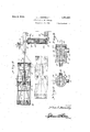
- Figure 8 is al transverse sectional view through one of the control valves, taken substantially along a line 8 8, of Figure 2,
- Figure 9 is a longitudinal sectional view through the valve, taken along a line 99 of Figure 8
- Figure 10 is a' detail of the pivoted arm actuating one of the valves through the ver-y ltical movement o'f the stacker arm,
- Figure 11 is a detail of the pawl and ratchet mechanism for the vertical adjusting screw -vforv controlling'the extent of vertical movement of the stack'er arm,
- Figure l2 is a fragmentary elevational view, with parts broken away and shown in section, of the verticalv adjusting screw and j pivoted valve controllever carried thereby,
- Figure 13 is a detail of the stop member associated with the-vacuum cup release controlmechanism
- FIG. 14 is a detail of the control member associated with the vacuum cup release mechanism,v
- Figure 15 is a; plan view of the automatic adjusting mechanism for the vacuum cup re-' lease means
- Figure '17 is a vertical sectional view through the automatic adjusting mechanism ⁇ frame 10.
- the apparatus in its present embodiment includes a frame 5 within which is ⁇ journalled a vertically disposed shaft 6 having a bore of square shape in cross section extending therethrough and within which is slidably mount-l ved a square shaped standard 7. To the upper end of the standard 7 is attached a tubular horizontal arm 8 to the outer end of which is attached a .clamping member 9 roviding means for suspending' a subst-antlally rec- ⁇ tangular -shaped vacuum cup supporting
- the frame 10 is horizontally disposed as clearly illustrated in Figui-e1 of the drawings and is provided with a plurality of rock shafts 11 extending transversely of the frame upon each ofwhich is secured a plurality of laterally extending arms 12 with cables 13 at. tached at their outer ends andk secured to vacuum cup releasing .levers 1'4 arranged adjacent the edges of a series of vacuum cups 15, of a construction well known, in the art,
- Thev vacuum cup' 15 may be adjusted verti- I cally with respect to the frame by means Vof socket 17 carried by the frame and through which the upper ends of the r'od 16 are slid ably inserted and retained in position therein by set screws 18.
- Vof socket 17 carried by the frame and through which the upper ends of the r'od 16 are slid ably inserted and retained in position therein by set screws 18.
- the rock shafts 11 are connected for uniform movement by a longitudinally'extending tie rod 19 connected to the shafts through levers 20, said tie rod lbeing provided with an upwardly extending arm 21 tothe upper end of which is secured theouter end of a v stem 22 inserted through one end of a cylinder 23 carried by the frame, and with its inner endattached to a kpiston-'24 operatively arranged within said cylinder.
- the piston 24 is operated byfa Huid pressure, preferably compressed air,' admitted into the opposite end to the cylinder 23 through air hose 26 extending through the tubular arm 8 and extending to a control.
- Huid pressure preferably compressed air
- This control valve is of a two-way construction sol as to alternately admit air into the opposite end of the cylinderfor reciprocally actuating the piston.
- the .upper portion Vof the frame 10 is pro- ⁇ vided with'a'bevel gear 29 rotatably mounted on a hanger 30vdependin from the/ clamp 9 and from which gear the rame 10is suspended.
- T he bevel gear 29l is operated through a pinion gear 31 attached-'to a shaft 32 jourvnaled in bearing brackets 33 carried-by the arm, Asaid shatbeing disposed parallel' thereto.
- the innerend of the shaft 32 is connected to Y:'Vvertically disposed telescoping shaft section 34 through a universal coupling 35, the
- the upper menber of the telescoping shaft section '34 is slidably disposedin a guide bracket 39. It will beapparent from the foregoingV thatv the rotary-movement of vthe Shaft'6 for swinging the arm 8 will be transmitted'to the' frame 10 sfo. as to rotate the framein a direction opposite from the swinging movement of the arm and thus maintain the same in parallel relation with respect to l the sheets of material to be stacked. At the same time the telescoping sections ofthe shaft ⁇ permitsvthe gears to be maintained in con-v stant engagement during the .vertical movement of the arm; o
- the lower end of the standard 7 is attached ⁇ to the outer end of a vertically disposed pis-l ton rod 40 extending through one end of a cylinder 41 and havlng a piston 42 attached at its lower end and operatively arranged inv said cylinder.
- Air hose' or pipes 43 and 44 are connected respectively at the upper and lower ends of the cylinder andextend to a4 control valve 45 togwhich a feedpipe 46 is attached and connected with a suitable supply of air under pressure (not shown).
- This control Valve 45 like the control valve 21, 1s adapted to alternately feed air into the opposite end ofthe cylinder forreciprocally actuating the piston 42 and thus raise and lower the frame 10 through the standard and. arm 7 and 8 respectively.
- An ⁇ arm 47 extends radially from one sideV horizontally'disposed, as clearly illustrated in Figures l and 2 of the drawings and is also connected at its opposite ends with air hose 53 and 54 communicating with a control valve l
- This control valve 55 is likewise adapted to alternately admit compressed air into the opposite ends of the cylinder 49 for reciprocally actuating the piston 50 therein and thus to rock the shaft 6 through the connection of the piston with thearm 47. In this manner provision is made for the forward and backward Aswinging of the arm 8 in a horizontal plane.
- valves 8 and 9 of the drawings include a cylindrical casing 56 having a connection 57 at one end for attaching a feed pipe extending to a suitable source of air under pressure.
- a rotor 58 is operatively mounted within the'casing having a vstem 59 extending outwardly through thecover plate 60 of the casing disposed at the end thereof opposite fromf the connection 57..l y
- the air passages 62 extendlaterally through the walls' of the rotor4 and are adapted to communicate selectively with connections 63 and 64 formed inthe walls of the casing at angles of ninety degrees with respect to each other andto .which the air hose leading to the oppo-4 site ends of the vvvcylinders are 'respectively attached.
- At diametrica'lly opposite sidesof the rotor 158 is a pair of longitudinally extending grooves 65 terminating atvone end in av circumferentially extending groove66; each of said vrcmuferential grooves extending only-part way about the surface of the rotor.
- An exhaust port 67 is formed in the casing 56 in a position for communicating with the respective grooves 66 upon a predetermined positioningof the rotorand when either of the grooves 65 are in a position for communication with either of the connections 63 or 64.
- the grooves 65 are arranged in position upon the rotor at angles of ninety degrees with respect tc the vlateral passages 62 so that when one of thc lateral passages is' in communication with one of the connections 63 or 64, one of the grooves 65 will be in communication with the other of said connections.
- a ratchet 68 To the stem 59 of the control valves 27 and 55 is attached a ratchet 68,.the ratchet 68 of the valve 55 being operatively engaged by a pawl 69 operated through a lever 7 0 pivotally attached intermediate its ends at 71 to a portion of the frame 5 and with the end of the lever remote from the pawl terminating adjacent the standard 7 for engagement by a stop 72 adjustably carried on the standard for actuating the lever upon the upward movement thereof.
- the control valve 45 for controlling the vertical movement of the standard 7 has the stem of its rotor provided with an'arm 73, illustrated in detail in Figure l() of the drawing, which extends transversely of the valve-cas- ,ing with its ends protruding at opposite sides thereof.
- the Stem 59 of the Valve rotor is inserted in a slotted opening 74 of the arm to permit transverse sliding movement of the arm and is urged in one transverse direction by a spring 75 interposed ⁇ in the slottedopening between the end thereof and said stem.
- the arm 7 3 extends in a generally verticaldirection with its upper end disposed in the path of movement of the arm 47 of the gear ⁇ 6. Accordingly during the movement of the arm 47, the same will engage the upper end ofthe varm 7 3 so as to actuate the valve and moving Nys the rotor thereof one position for admitting. air to one end of the cylinder 41.
- the arm 47 for effecting a swinging movement of the stacker arm 8 from one of its extreme positions to the other, the arm 47'rides over the end of the arm 73 and the latter arm is then returned to its original position by a spring 76. Through this action the valve is -then returned to its original position for admitting l the airinto the opposite end of the cylinder 41 whereby to actuate the piston 42 and alternately raise and lower the standard 7.
- an automatic adjusting mechanism is provided Vfor limiting such vertical movement of the stacker arm by actuating the valve tervals.
- This adjusting mechanism comprises a vertically disposed screw 77 having its upper and lower ends reversedly threaded, as clearly illustrated in Figure 12 of the drawing and, nponthe lower end of which is threaded a at greater or more frequent inblock 78 and with a similar block 79 threaded on the upper portion thereof, the blocks'thus being adaptedfor opposite vertical movement upon the rotation 'of the screw.
- a trip' 81 is pivotally attached to the upper block 79 andto-which is attached one end of av cable-82 extending upwardly over a pulley 83 carried at the lower end of the arm 73 and extending downwardly with its opposite end attached to the lowermost block 78.
- a ratchet ⁇ wheel 84 At the upper end of the screw 77 is arranged a ratchet ⁇ wheel 84 with which a pawl 85 is operatively engaged and slidably mounted in a guide-86 secured to the frame by av 'f I hracket87fand with one end arranged in the path o 'f movement ofthe upper end of the arm 7 8 as clearly illustrated in Figure 10 of the drawings.
- the trip 81 is ⁇ disposed in the path of movement of the stop 7 2 and adapted for engagement by said stop upon its downward movement. Accordingly upon each downward movement of the standard 7 the vtrip 81 is moved downwardly and through its engagement with the lower end ofthe arm 7 3 operates to return said arm to its original position after being released from the arm 47
- the cable 82 is always maintained in a taut condition through the opposite movement of theblocks 78 and 79 upon'the screw and it will be apparent that as the block 79 isadj usted upwardly upon the screw the interval of engagement of the trip by the stop 72 1s reduced to effect an earlier return of lthe arm 7 3.
- the sliding connection of the arm upon the valve permits a disengagement of the arm f from the upper horizontal yswinging arm 47.
- a mechanism is also provided for controlling the releasing action of the vacuum cup 15 'through the actuation of the control valve 27 an'd adapted forv adjustment so as to time the releasing action of the cup in accordance with the adjustment in the extent of vertical movement of the stacker arm.
- This control valve 27 also has its stem provided with a ratchet wheel88, with which a pawl 89 is op- Ieratively engaged and extends vertically of the frame with its upper end formed into a screw 90.
- a threaded rod 91 isdisposed .parallel with ythe screw 90 with its lowe;A end rigidly secured-to the frame 5.
- a ring member 100 is formed at the end ofthe frame members 99 remote from the pawl 89 and is disposed horizontally so as to permit the free vertical movement of the standard 7 therethrough.
- the projections 102 are adapted to pass freely through the ring during the vertical movement of the standard 7 when the stacker arm 8 has been swung in onel direction and are adapted for engagement with the lugs 101 of the ring during such vertical move- I ment? when'the stacker arm has been swung p into its operative position.
- Each movement ofthe pawl 89 serves-to reverse the position of the control valve 27 wherebyto control the engaging or releas- 1n ⁇ movement-of the vacuum cup.
- a bell crank lever 104 is pivoted upon a bracket 105 carried -by the sleeve associated with the sprocket wheel 93 and to which lever is operatively attached a pawl 106 engageable with a' set of ratchet4 teeth 107 formed on the upperrface of the sprocket wheel 93.
- kAna'djust/able stop 109 is carried by one4 of the sleeves ⁇ 95 tor engaging the under side of the pivoted frame 99 whereby to limit the downward movement of the end of the frame disposed adjacent the'pawl 89.
- the pawl 89 is also slidably extended through a guide 110 to insure the engagement thereof with its associated ratchet wheel.
- the stop 103 is positioned upon thestandard 7 so that the projections 102 of the stop will engage the lugs 101 of the pivoted frame for reversing I the position of the control valve 27 only upon each complete forward and backward swinging movement of the stacker arm so that the vacuum cup will be released from the sheet of material only when the arm has been swung into position upon the sheets which are being stacked, or in such a position where 1t is de sired to release the sheets.
- a 'stacker comprising a rotatable standard mounted for vertical sliding movement, a horizontal stacker arm at the upper end of the standard, -independent fluid pressure operating means for the standard and the arm arranged to reversibly actuate the same in their respective movements and automatic control means y,for said operatingmeans providing for the movement of the standard and the arm in predetermined timed relation, and operable through the movement of said standards.
- a stacker comprising a vertically and horizontally movable stacker arm, independent fucid pressure operating-means for the 'arm arranged to reciprocally actuate the same in its respective movements and automatic control means for said operating means providing for the various movements of the arm in predetermined timed relation, and
- said operating means comprising cylinders having pressurev operated pistons arranged therein and means operatively connecting the same with the arm fort-he simultaneous vertical andA horizontal movement thereof.
- a stacker comprising a rotatable standard mounted for vertical sliding movement, va horizontal' stacker arm at the upperjend of the standard, work gripping elements carried at the outer end of the arm, means carried by the arm for releasing said gripping means from the work', independent fluid pressure voperating means for the standard, for said arm and for said releasing means arranged to actuate the same in a predetermined timed relation and automatic control means for said operating means, said control means being operatively associated with the ment of the arm.
- a stacker comprising a vertically and ⁇ operating means, and operable through the movement of the arm, said operating means for said arm and said work releasing means comprising cylinders having pressure operated pistons arranged therein, said arm operating means being operatively connected with the arm for the simultaneous vertical and horizontal movement thereof.
- A-stacke'r comprisi'n a verticallyand horizontally movable stac er arm, work engaging -means carried by said arm, work releasing means carried by the arm and. operatively connected the engaging actuating the arm in its respective movement,
- a st'ac er comprising'a vertically and horizontally'movable stacker arm, Work engaging means carried by said arm, work releasing means carried by the arm and operatively connected With the-engaging means, iiuid pressure operating means for the ⁇ arm v and said work releasing means, automatic control means for said operating means and ⁇ operable throughV a predetermined vertical movementof the arm and means for malntaining the Work engaging means in a parallel position with the stacked work during the movement of the arm, said paralleling means comprising a gear operable through the horizontal swinging movement of the arm, a gear carried by said work engaging meansand a -lexible shaft carried by the arm having pinion 4gears at each end operatively connected with said first named gears.
- a stacker comprisin'gfa vertically and #so horizontally movable stacker arm, independentv fluid pressureoperating means for .actuating the arm in itsrespective movement,- v.automatic control meansf for said operatrng" means adapted to ⁇ reverse the operation there- .of at predetermined intervals and automatic means for decreasing the interval of the reversing movement of the vertical-operating means when the arm reaches its predetermined position during its horizontal move- ⁇ ment and operable by each successive vertical movement of the arm. 4
- Al stacker comprising a vertically and horizontally movable stacker arm, ,independent Huid pressure operatingmeans for of at predetermined intervals, work engaging vacuum cups carried by the arm,' releasing means for the cups, automatic control means fr saidf ⁇ operating means and said vacuum cup releasing means, said control means for the operating-means being adapted to re-V verse the operation thereof at predetern'iinedy 8.
- a stacker comprising -a vertically and horizontally movable stacker farm, inde-l pendent fluid pressure voperating means Vfor actuating the arm in its respective movement, automatic control means forsaid operating ⁇ means adapted to reverse ⁇ the operation thereof at predetermined intervals, work engaging vacuum cups carried by the arm, releasing means for the cup, automatic control means for4 said operating means'and said vacuum cup releasing means, saidv control means for the operating means being adapted to reverse the operation-thereof atpredeterrnined intervals and independent meansfor automatically decreasing the interval of the reversing movement of the Vertical operating means and for the operation ofsaid releasing means.
- a stacker comprising a vertically and horizontally movable stacker arm, independent fluid pressure operating means for ac-' tuating the arm in its res ective movement,
- automatic control means orsaid operating means adapted to reverse the operation therei of at predetermined intervals, work engaging vacuum cups carried by the arm, releasing means for the cup, automatic control means for said. operating means and said vacuum cup releasing means, said'cont'rol means forv theoperating means being adapted to reverse the operation thereof at predetermined intervals and independent means for automatically decreasing the intervalfof the l treversing movement of the vertical operating means vand for the operation of said releasing ing'operable uniformly by successive vertical movement of the arm when the arm reaches a predetermined tal movement.
- a stacker comprising a vertically and horizontally movable stackerarm, independent Huid pressure operating means for actuating the arm in its respective movement,
- said last named automatic means beposition during its'horizonmeans adapted to reverse the operation thereof at predetermined intervals, work engaging vacuum cups carried by the arm, releas.
- a stacker comprising a vertically and horizontally movable stacker arm, reversible fluid pressure operating means for the arm,
- automatic control means for said operating means adapted to reverse the operation thereof at predetermined intervals, Work engaging vac-uum cups carried by the arm, releasing means for the cups, automatic control means for said operating means and vacuum cup releasing means, independent means for automatically decreasing the intervals in reversing movement of the vertical operating means and for the operation of said releasing means, said automatic control means comprising fluid pressure control valves communieating with the operating means for reversing the movement thereof, actuating means for the valves and operating means carried by the arm engageable with said valve actuating means and arrangedfor operating the valves-upon a predetermined movement of the arm.
- a stacker comprising'a vertically and horizontally movable stacker arm, reversible fluid pressurel operating means for the arm, automatic control means for said operating means adapted to reverse the operation thereof at predetermined intervals, Work engaglv ing vacuum cupscarried by the arm, releasing'means for the cups, automatic control means for said operating means and vacuum cup releasing means, independent means for automatically decreasing the intervals in reversing movement of the vertical operating means and for the operation of said releasing means, said automatic control means comprisinguid pressure control valves communicating with the operating means for reversing the movement thereof, actuating means for the valve and operating means carried by the arm engageable with said valve actuating means and arranged' for operating the valve 'upon a predetermined movement of the arm, and mea-ns connecting the valve actuating means with the automatic reversing and control means for maintaining the same inuniform relative position.
Landscapes
- Engineering & Computer Science (AREA)
- Mechanical Engineering (AREA)
- Sheets, Magazines, And Separation Thereof (AREA)
Description
June 3, 1930. E; L. DONNELLY AUTOMATIC SHEET STACKER Filed Oct. 5l, 1928 4 Sheets-Sheet Inventor Z732 0.5 L. Fofana/Zi 'By @m /lttornqy Junel3, 1930. l E. L. DQNNELLY 1,761,881
AUTOMATIC SHEET STACKER Filed Oou. 31, 1928 4 Sheets-Sheet 2 Inventor Zaaslx//zhel@ Ahorn@ June 3. 1930.y
` E. L. DONNELLY AUTOMATIC SHEET ,STACK'ER 4 Filed'ocr. 51, 192e 4 sheetssheet 5v June 3, 1930."
E. L. DONNELLY 1,761,881
AUTOMATIC SHEET STACKER Filed Oct. 51, 1928 4 Sheets-Sheet 4 las vliateritetl June 3, 1930 UNITE-D STATES PATENT oFjFlcE "ENOS L.- ,DONNELLY, OF HUNTINGTON, 'WESTVIRGINIA AU'roMA'rro sHra'r s'rAcKER Application filed October 311928. SerialNm 316,247.
The present invention relates to automatic sheet stackers Adesigned 'particularly for 'use in the sheet 'metal industry where sheets of material are to be moved from one stack to 5 another, or in feeding sheets from a stack to the rolling mill or the like and removing the sheets from the mill and stacking the same. j
One of the important objects of the invenflo tion is to provide an apparatus of this'character embodying ymeans for engaging the uppermost sheet. of the stack and lifting,
swinging'and lowering the same while maintained in a horizontal position, the lposition of the sheet when lowered, being parallel to its original position, the mechanism provided j for accomplishing such movement of the sheet being automatic in its operation. l
A further important object of the inven- 29 tion is to provideL a set of vacuum cup sheet metal gripping-members adapted upon engagement with the sheet for lifting and moving' the same together with means 'for automatically releasingithe sheet upon a predetermined movement ofthe apparatus.
. Another important object is to provide a stacker armf mounted for vertical and hori-` zontal swinging movement and providing said arm and said control means for the` vacuum cup with an automatic adjusting apparatus whereby to .automatically .adjust the extent of vertical movement of the arm' as well as the interval between each releasing action of the cup'in accordance with the increase or decrease of the stack of sheet material.' i v A further important objectof theinvention'is to provide an apparatus of this character arranged for operation by fluldpressure.
Other objects and advantages reside in the special construction, combination and arrangement of lthe various elements forming the invention 'as more fully hereinafter described and claimed, reference being had to the accompanying drawings formlng 'part hereof, whereinv like numerals refer to like 4parts throughout, and in which:
' Figure 1 is a view in side elevation of the .a linee-4 of Figure 3,
Figure 5 is a vertical sectional view through one of the vacuum cups,
Figure 6 is a sectional view through the stacker arm showing thegear provided for retaining the sheet in parallel position during swinging of the arm,
Figure 8 is al transverse sectional view through one of the control valves, taken substantially along a line 8 8, of Figure 2,
Figure 9 is a longitudinal sectional view through the valve, taken along a line 99 of Figure 8, Figure 10 is a' detail of the pivoted arm actuating one of the valves through the ver-y ltical movement o'f the stacker arm,
' .Figure 11 is a detail of the pawl and ratchet mechanism for the vertical adjusting screw -vforv controlling'the extent of vertical movement of the stack'er arm,
Figure l2 is a fragmentary elevational view, with parts broken away and shown in section, of the verticalv adjusting screw and j pivoted valve controllever carried thereby,
Figure 13 is a detail of the stop member associated with the-vacuum cup release controlmechanism,
Figure 14 is a detail of the control member associated with the vacuum cup release mechanism,v
Figure 15 is a; plan view of the automatic adjusting mechanism for the vacuum cup re-' lease means,
'Figure 16 -is a sectional View through one of the'socket .wheels thereof, taken along a linel-l'of Figure 15, and
Figure '17 is a vertical sectional view through the automatic adjusting mechanism `frame 10.
The apparatus in its present embodiment includes a frame 5 within which is `journalled a vertically disposed shaft 6 having a bore of square shape in cross section extending therethrough and within which is slidably mount-l ved a square shaped standard 7. To the upper end of the standard 7 is attacheda tubular horizontal arm 8 to the outer end of which is attached a .clamping member 9 roviding means for suspending' a subst-antlally rec-` tangular -shaped vacuum cup supporting The frame 10 is horizontally disposed as clearly illustrated in Figui-e1 of the drawings and is provided with a plurality of rock shafts 11 extending transversely of the frame upon each ofwhich is secured a plurality of laterally extending arms 12 with cables 13 at. tached at their outer ends andk secured to vacuum cup releasing .levers 1'4 arranged adjacent the edges of a series of vacuum cups 15, of a construction well known, in the art,
' said cups being suspended from the frame 10 byvertical rod 16.A By Aforcing the center of the cups downwardlyby thedownward movement of the frame 10, the cups will be fiat-tened out upon the surface of the sheet of material. Accordingly by releasing the cables 13 of any upward pull and allowing the cups to returnto their normal position up'on y the upward movement of the frame, a vac uum Will be created at the under side of the cup causing the edges thereofv to grip the material for lifting the same. The releasing ofthe cup will be accomplished by raising the frame 10 while retaining t-he -cup in a flattened condition by the proper manipulation of the cable 13.
Thev vacuum cup' 15 may be adjusted verti- I cally with respect to the frame by means Vof socket 17 carried by the frame and through which the upper ends of the r'od 16 are slid ably inserted and retained in position therein by set screws 18. l l
The rock shafts 11 are connected for uniform movement by a longitudinally'extending tie rod 19 connected to the shafts through levers 20, said tie rod lbeing provided with an upwardly extending arm 21 tothe upper end of which is secured theouter end of a v stem 22 inserted through one end of a cylinder 23 carried by the frame, and with its inner endattached to a kpiston-'24 operatively arranged within said cylinder.
yThe piston 24 is operated byfa Huid pressure, preferably compressed air,' admitted into the opposite end to the cylinder 23 through air hose 26 extending through the tubular arm 8 and extending to a control.
valve 27. This control valve is of a two-way construction sol as to alternately admit air into the opposite end of the cylinderfor reciprocally actuating the piston.
Upon the movement of the piston in one direction the tie rod 19 is actuated so as to partially rotate each of the rock shafts l1 and through their connection with the vacuvum cup releasing levers 14 tobreak the vacuum and permit disengagement of. the cup from the sheet of material, indicated at 28 y in Figure 1 of the drawings. The movement of the piston in the opposite direction permits a return of the cups to their normal position `for gripping the sheet of material and hoist the same upon the vertical movement of the standard 7 in amanner to be presently ex-k i plained.
.In order that the sheet may be moved from one position to another, in parallel relation,
the .upper portion Vof the frame 10 is pro-` vided with'a'bevel gear 29 rotatably mounted on a hanger 30vdependin from the/ clamp 9 and from which gear the rame 10is suspended. T he bevel gear 29l is operated through a pinion gear 31 attached-'to a shaft 32 jourvnaled in bearing brackets 33 carried-by the arm, Asaid shatbeing disposed parallel' thereto.
v vThe innerend of the shaft 32 is connected to Y:'Vvertically disposed telescoping shaft section 34 through a universal coupling 35, the
lower portion ofthe telescoping shaft section indicated at' 36 being journaled in the frame 5 andis provided at its lower end with a pinion gear 37 operabley through a gear 38 formed on the shaft 6. 4 y
The upper menber of the telescoping shaft section '34 is slidably disposedin a guide bracket 39. It will beapparent from the foregoingV thatv the rotary-movement of vthe Shaft'6 for swinging the arm 8 will be transmitted'to the' frame 10 sfo. as to rotate the framein a direction opposite from the swinging movement of the arm and thus maintain the same in parallel relation with respect to l the sheets of material to be stacked. At the same time the telescoping sections ofthe shaft `permitsvthe gears to be maintained in con-v stant engagement during the .vertical movement of the arm; o
' The lower end of the standard 7 is attached `to the outer end ofa vertically disposed pis-l ton rod 40 extending through one end of a cylinder 41 and havlng a piston 42 attached at its lower end and operatively arranged inv said cylinder. Air hose' or pipes 43 and 44 are connected respectively at the upper and lower ends of the cylinder andextend to a4 control valve 45 togwhich a feedpipe 46 is attached and connected with a suitable supply of air under pressure (not shown).
This control Valve 45. like the control valve 21, 1s adapted to alternately feed air into the opposite end ofthe cylinder forreciprocally actuating the piston 42 and thus raise and lower the frame 10 through the standard and. arm 7 and 8 respectively.
i An `arm 47 extends radially from one sideV horizontally'disposed, as clearly illustrated in Figures l and 2 of the drawings and is also connected at its opposite ends with air hose 53 and 54 communicating with a control valve lThis control valve 55 is likewise adapted to alternately admit compressed air into the opposite ends of the cylinder 49 for reciprocally actuating the piston 50 therein and thus to rock the shaft 6 through the connection of the piston with thearm 47. In this manner provision is made for the forward and backward Aswinging of the arm 8 in a horizontal plane.
The construction' of the control valves 27,
45 and 55 is illustrated in detail in Figures Each of the valves 8 and 9 of the drawings. include a cylindrical casing 56 having a connection 57 at one end for attaching a feed pipe extending to a suitable source of air under pressure. y
A rotor 58 is operatively mounted within the'casing having a vstem 59 extending outwardly through thecover plate 60 of the casing disposed at the end thereof opposite fromf the connection 57..l y
The end of the rotor adj acent the air intake connection 57,'is vformedwith a central bore 6 1 communicating with said connection, said lbore 'terminating Within the rotor ina" pairof. oppositely1 extending air passages 62.
' The air passages 62 extendlaterally through the walls' of the rotor4 and are adapted to communicate selectively with connections 63 and 64 formed inthe walls of the casing at angles of ninety degrees with respect to each other andto .which the air hose leading to the oppo-4 site ends of the vvvcylinders are 'respectively attached. l
At diametrica'lly opposite sidesof the rotor 158 is a pair of longitudinally extending grooves 65 terminating atvone end in av circumferentially extending groove66; each of said vrcmuferential grooves extending only-part way about the surface of the rotor. An exhaust port 67 is formed in the casing 56 in a position for communicating with the respective grooves 66 upon a predetermined positioningof the rotorand when either of the grooves 65 are in a position for communication with either of the connections 63 or 64.
As will he clearly observed from an inspection-of Figure 8 of the drawings, the grooves 65 are arranged in position upon the rotor at angles of ninety degrees with respect tc the vlateral passages 62 so that when one of thc lateral passages is' in communication with one of the connections 63 or 64, one of the grooves 65 will be in communication with the other of said connections.
Thus when one air hose of the respective cylinders is in communication with the feed pipe connection 57, the other air hose is in communication with the exhaust or discharge port 67so that the air from the discharge end of the piston ywill be permitted to discharge into the atmosphere.
To the stem 59 of the control valves 27 and 55 is attached a ratchet 68,.the ratchet 68 of the valve 55 being operatively engaged by a pawl 69 operated through a lever 7 0 pivotally attached intermediate its ends at 71 to a portion of the frame 5 and with the end of the lever remote from the pawl terminating adjacent the standard 7 for engagement by a stop 72 adjustably carried on the standard for actuating the lever upon the upward movement thereof.
It will be observed from an inspection of Figure l of the drawing that the ratchet 68 is of asaw toothed construction whereby to provide for a quarter revolution of the rotor .58 of the valve upon each upward movement of the standard 7. i
Accordingly each time the standard is raised the piston 50 in the cylinder 49 is actuated for swinging the arm in either a'forward 1 or reversed direction, as the case may be.
The control valve 45 for controlling the vertical movement of the standard 7 has the stem of its rotor provided with an'arm 73, illustrated in detail in Figure l() of the drawing, which extends transversely of the valve-cas- ,ing with its ends protruding at opposite sides thereof.
The Stem 59 of the Valve rotor is inserted in a slotted opening 74 of the arm to permit transverse sliding movement of the arm and is urged in one transverse direction by a spring 75 interposed `in the slottedopening between the end thereof and said stem.
As illustrated in Figure l of the drawings, the arm 7 3 extends in a generally verticaldirection with its upper end disposed in the path of movement of the arm 47 of the gear` 6. Accordingly during the movement of the arm 47, the same will engage the upper end ofthe varm 7 3 so as to actuate the valve and moving Nys the rotor thereof one position for admitting. air to one end of the cylinder 41.
At the ccmpletion of the movement of the arm 47, for effecting a swinging movement of the stacker arm 8 from one of its extreme positions to the other, the arm 47'rides over the end of the arm 73 and the latter arm is then returned to its original position by a spring 76. Through this action the valve is -then returned to its original position for admitting l the airinto the opposite end of the cylinder 41 whereby to actuate the piston 42 and alternately raise and lower the standard 7.
j In order to regulate the extent of vertical movement of the stacker arm, in accordance withan increase or decrease in the size of the stack of the sheets, an automatic adjusting mechanism is provided Vfor limiting such vertical movement of the stacker arm by actuating the valve tervals.
This adjusting mechanism comprises a vertically disposed screw 77 having its upper and lower ends reversedly threaded, as clearly illustrated in Figure 12 of the drawing and, nponthe lower end of which is threaded a at greater or more frequent inblock 78 and with a similar block 79 threaded on the upper portion thereof, the blocks'thus being adaptedfor opposite vertical movement upon the rotation 'of the screw.
y* Oneendlof' each of the blocks is provided with" a :vertical opening through which aguide 80-`is inserted permitting vertical sliding movement yof the'block onthe guide, the
' guideserving to prevent'rotary movement of y the block during thel rotation of the screw. A trip' 81 is pivotally attached to the upper block 79 andto-which is attached one end of av cable-82 extending upwardly over a pulley 83 carried at the lower end of the arm 73 and extending downwardly with its opposite end attached to the lowermost block 78.
At the upper end of the screw 77 is arranged a ratchet `wheel 84 with which a pawl 85 is operatively engaged and slidably mounted in a guide-86 secured to the frame by av 'f I hracket87fand with one end arranged in the path o 'f movement ofthe upper end of the arm 7 8 as clearly illustrated in Figure 10 of the drawings. j
Accordingly upon each movement of the arm 7 3 in a direction toward the pawl, the
ratchet wheel 8.4 associated therewith will be actuated for rotating the screw 77 and eEeetling anadjustment of the blocks-7 8 and 79 thereon. l
The trip 81 is`disposed in the path of movement of the stop 7 2 and adapted for engagement by said stop upon its downward movement. Accordingly upon each downward movement of the standard 7 the vtrip 81 is moved downwardly and through its engagement with the lower end ofthe arm 7 3 operates to return said arm to its original position after being released from the arm 47 The cable 82 is always maintained in a taut condition through the opposite movement of theblocks 78 and 79 upon'the screw and it will be apparent that as the block 79 isadj usted upwardly upon the screw the interval of engagement of the trip by the stop 72 1s reduced to effect an earlier return of lthe arm 7 3. The sliding connection of the arm upon the valve permits a disengagement of the arm f from the upper horizontal yswinging arm 47.
A mechanism is also provided for controlling the releasing action of the vacuum cup 15 'through the actuation of the control valve 27 an'd adapted forv adjustment so as to time the releasing action of the cup in accordance with the adjustment in the extent of vertical movement of the stacker arm. This control valve 27 also has its stem provided with a ratchet wheel88, with which a pawl 89 is op- Ieratively engaged and extends vertically of the frame with its upper end formed into a screw 90.
A threaded rod 91 isdisposed .parallel with ythe screw 90 with its lowe;A end rigidly secured-to the frame 5. Sprocket wheels 92- allel frame members 99 disposed at opposite sides of the sleeve. v
A ring member 100 is formed at the end ofthe frame members 99 remote from the pawl 89 and is disposed horizontally so as to permit the free vertical movement of the standard 7 therethrough. 'l A pair of lugs V101are disposed at .diametrically opposite sides atthe inner periphery of the ring and on the vare pivotally carried in a pair'of spaced parare adapted for engagement by a pair of projections 10.2 formed at diametrically opposite sides of astop 103 secured to the standard above the-frame 5.
The projections 102 are adapted to pass freely through the ring during the vertical movement of the standard 7 when the stacker arm 8 has been swung in onel direction and are adapted for engagement with the lugs 101 of the ring during such vertical move- I ment? when'the stacker arm has been swung p into its operative position.
f Upon the engagement of the lugs '101 by said projections of thestop the frame composed of the parallel members 99 will be pivotally actuated through its mounting on the rod 99 bythe trunnion'so as to actuate the pawl 89.
A Each movement ofthe pawl 89 serves-to reverse the position of the control valve 27 wherebyto control the engaging or releas- 1n` movement-of the vacuum cup.
the reifersing action of the cylinder control- 'in the vacuum cup in accordance with the variation in the extent of vertical movement of the" standard, provision is made for vertica'lty adjusting the sprocket wheels 92 whereby toadjust the ring 100 with respect-to the stop 103.
For Athis purpose `a bell crank lever 104 is pivoted upon a bracket 105 carried -by the sleeve associated with the sprocket wheel 93 and to which lever is operatively attached a pawl 106 engageable with a' set of ratchet4 teeth 107 formed on the upperrface of the sprocket wheel 93.
kAna'djust/able stop 109 is carried by one4 of the sleeves`95 tor engaging the under side of the pivoted frame 99 whereby to limit the downward movement of the end of the frame disposed adjacent the'pawl 89. The pawl 89 isalso slidably extended through a guide 110 to insure the engagement thereof with its associated ratchet wheel.
It is to be understood that the stop 103 is positioned upon thestandard 7 so that the projections 102 of the stop will engage the lugs 101 of the pivoted frame for reversing I the position of the control valve 27 only upon each complete forward and backward swinging movement of the stacker arm so that the vacuum cup will be released from the sheet of material only when the arm has been swung into position upon the sheets which are being stacked, or in such a position where 1t is de sired to release the sheets.
It will be apparent from the foregoing that by initially positioning the rotors of the respective valves in the proper manner `with respect to the compressed air feed pipe eX- tending to t-he opposite ends of the associated cylinders that the stacker arms will pick up the sheets of material singly, hoist the same and swing the sheets into a predetermined osition whereupon the sheets arelreleased rom the vacuum cup and the arm is returned to itsoriginal position and lowered for repeating the operation.
It is obvious that my invention is suscepti ble to various changes and moditicationsin vconstruction without departing fromv v the spirit of the, invention or the scope of the appended claims, and I. accordingly claim all suhdforms of the device to which l am en- .r i y.
order to regulate the intervalbetween Having thus described my invention, what I claim'a's new is:
l. A 'stacker comprising a rotatable standard mounted for vertical sliding movement, a horizontal stacker arm at the upper end of the standard, -independent fluid pressure operating means for the standard and the arm arranged to reversibly actuate the same in their respective movements and automatic control means y,for said operatingmeans providing for the movement of the standard and the arm in predetermined timed relation, and operable through the movement of said standards.
2. A stacker comprising a vertically and horizontally movable stacker arm, independent f luid pressure operating-means for the 'arm arranged to reciprocally actuate the same in its respective movements and automatic control means for said operating means providing for the various movements of the arm in predetermined timed relation, and
operable through the movement of said arm,
said operating means comprising cylinders having pressurev operated pistons arranged therein and means operatively connecting the same with the arm fort-he simultaneous vertical andA horizontal movement thereof.
3. A stacker comprising a rotatable standard mounted for vertical sliding movement, va horizontal' stacker arm at the upperjend of the standard, work gripping elements carried at the outer end of the arm, means carried by the arm for releasing said gripping means from the work', independent fluid pressure voperating means for the standard, for said arm and for said releasing means arranged to actuate the same in a predetermined timed relation and automatic control means for said operating means, said control means being operatively associated with the ment of the arm.
4. A stacker comprising a vertically and `operating means, and operable through the movement of the arm, said operating means for said arm and said work releasing means comprising cylinders having pressure operated pistons arranged therein, said arm operating means being operatively connected with the arm for the simultaneous vertical and horizontal movement thereof. j y
5. A-stacke'r comprisi'n a verticallyand horizontally movable stac er arm, work engaging -means carried by said arm, work releasing means carried by the arm and. operatively connected the engaging actuating the arm in its respective movement,
automatic control means for said operating'vv means adapted to reverse the operatlon therei operating means loperable -to reverse the operation thereof, means carried by the arm,
means, fluid-pressure operated'm'eans vfor the arm, automatic control means'for sald operable through a predetermined movement thereof for actuating said control means and means for maintaining the work engaging means in a parallel position with the stacked Workdurin the movement of the arm` 6. A st'ac er comprising'a vertically and horizontally'movable stacker arm, Work engaging means carried by said arm, work releasing means carried by the arm and operatively connected With the-engaging means, iiuid pressure operating means for the `arm v and said work releasing means, automatic control means for said operating means and `operable throughV a predetermined vertical movementof the arm and means for malntaining the Work engaging means in a parallel position with the stacked work during the movement of the arm, said paralleling means comprising a gear operable through the horizontal swinging movement of the arm, a gear carried by said work engaging meansand a -lexible shaft carried by the arm having pinion 4gears at each end operatively connected with said first named gears.
` 7. A stacker comprisin'gfa vertically and #so horizontally movable stacker arm, independentv fluid pressureoperating means for .actuating the arm in itsrespective movement,- v.automatic control meansf for said operatrng" means adapted to` reverse the operation there- .of at predetermined intervals and automatic means for decreasing the interval of the reversing movement of the vertical-operating means when the arm reaches its predetermined position during its horizontal move-` ment and operable by each successive vertical movement of the arm. 4
' 9. Al stacker comprising a vertically and horizontally movable stacker arm, ,independent Huid pressure operatingmeans for of at predetermined intervals, work engaging vacuum cups carried by the arm,' releasing means for the cups, automatic control means fr saidf` operating means and said vacuum cup releasing means, said control means for the operating-means being adapted to re-V verse the operation thereof at predetern'iinedy 8. A stiackerlomprising a vertically and-y intervals and automatic means for decreasing lthe interval of the reversing movement of the verticaloperating means and inthe operatlon' of said releasing means. y .\10. A stacker comprising -a vertically and horizontally movable stacker farm, inde-l pendent fluid pressure voperating means Vfor actuating the arm in its respective movement, automatic control means forsaid operating `means adapted to reverse `the operation thereof at predetermined intervals, work engaging vacuum cups carried by the arm, releasing means for the cup, automatic control means for4 said operating means'and said vacuum cup releasing means, saidv control means for the operating means being adapted to reverse the operation-thereof atpredeterrnined intervals and independent meansfor automatically decreasing the interval of the reversing movement of the Vertical operating means and for the operation ofsaid releasing means. I
11. A stacker comprising a vertically and horizontally movable stacker arm, independent fluid pressure operating means for ac-' tuating the arm in its res ective movement,
automatic control means orsaid operating means adapted to reverse the operation therei of at predetermined intervals, work engaging vacuum cups carried by the arm, releasing means for the cup, automatic control means for said. operating means and said vacuum cup releasing means, said'cont'rol means forv theoperating means being adapted to reverse the operation thereof at predetermined intervals and independent means for automatically decreasing the intervalfof the l treversing movement of the vertical operating means vand for the operation of said releasing ing'operable uniformly by successive vertical movement of the arm when the arm reaches a predetermined tal movement. c
12. A stacker comprising a vertically and horizontally movable stackerarm, independent Huid pressure operating means for actuating the arm in its respective movement,
automatic control means for said'operating means, said last named automatic means beposition during its'horizonmeans adapted to reverse the operation thereof at predetermined intervals, work engaging vacuum cups carried by the arm, releas.
ing means for the cup, automatic control means for saidnoperating means and said -vacuum cup releasing means, said control means for the operating -means being adapted to'reverse the operation thereof at predetermined intervals and independent means for automatically decreasing the interval ofthe reversing movement of the vertical operating means and for the operatlon of said releasingy means, said last named automaticmeans-lize` ing operable uniformly by successive `vertical movement of the arm when the arm reaches a predetermined `position during. -its las horizontal movement, and operating means carried by the arm for said last named automatic means and adapted to uniformly actuate the same upon the vertical movement of the arm in one direction.
13. A stacker comprising a vertically and horizontally movable stacker arm, reversible fluid pressure operating means for the arm,
l automatic control means for said operating means adapted to reverse the operation thereof at predetermined intervals, Work engaging vac-uum cups carried by the arm, releasing means for the cups, automatic control means for said operating means and vacuum cup releasing means, independent means for automatically decreasing the intervals in reversing movement of the vertical operating means and for the operation of said releasing means, said automatic control means comprising fluid pressure control valves communieating with the operating means for reversing the movement thereof, actuating means for the valves and operating means carried by the arm engageable with said valve actuating means and arrangedfor operating the valves-upon a predetermined movement of the arm. l
14. A stacker comprising'a vertically and horizontally movable stacker arm, reversible fluid pressurel operating means for the arm, automatic control means for said operating means adapted to reverse the operation thereof at predetermined intervals, Work engaglv ing vacuum cupscarried by the arm, releasing'means for the cups, automatic control means for said operating means and vacuum cup releasing means, independent means for automatically decreasing the intervals in reversing movement of the vertical operating means and for the operation of said releasing means, said automatic control means comprisinguid pressure control valves communicating with the operating means for reversing the movement thereof, actuating means for the valve and operating means carried by the arm engageable with said valve actuating means and arranged' for operating the valve 'upon a predetermined movement of the arm, and mea-ns connecting the valve actuating means with the automatic reversing and control means for maintaining the same inuniform relative position.
In testimony whereof I affix my signature.
4ENOS L. DONNELLY.
Priority Applications (1)
| Application Number | Priority Date | Filing Date | Title |
|---|---|---|---|
| US316247A US1761881A (en) | 1928-10-31 | 1928-10-31 | Automatic sheet stacker |
Applications Claiming Priority (1)
| Application Number | Priority Date | Filing Date | Title |
|---|---|---|---|
| US316247A US1761881A (en) | 1928-10-31 | 1928-10-31 | Automatic sheet stacker |
Publications (1)
| Publication Number | Publication Date |
|---|---|
| US1761881A true US1761881A (en) | 1930-06-03 |
Family
ID=23228211
Family Applications (1)
| Application Number | Title | Priority Date | Filing Date |
|---|---|---|---|
| US316247A Expired - Lifetime US1761881A (en) | 1928-10-31 | 1928-10-31 | Automatic sheet stacker |
Country Status (1)
| Country | Link |
|---|---|
| US (1) | US1761881A (en) |
Cited By (1)
| Publication number | Priority date | Publication date | Assignee | Title |
|---|---|---|---|---|
| US3168184A (en) * | 1963-04-23 | 1965-02-02 | Ingersoll Rand Co | Glass transfer apparatus |
-
1928
- 1928-10-31 US US316247A patent/US1761881A/en not_active Expired - Lifetime
Cited By (1)
| Publication number | Priority date | Publication date | Assignee | Title |
|---|---|---|---|---|
| US3168184A (en) * | 1963-04-23 | 1965-02-02 | Ingersoll Rand Co | Glass transfer apparatus |
Similar Documents
| Publication | Publication Date | Title |
|---|---|---|
| US2639894A (en) | Pipe and casing tongs | |
| CN102720446B (en) | Automatic derrick monkey of drilling machine | |
| CN105332663B (en) | A drill pipe column automatic discharge manipulator | |
| CN109322628A (en) | Small workover unmanned operation equipment | |
| CN202673198U (en) | Automatic derrick monkey of drilling machine | |
| CN203476256U (en) | Magnetic hoisting type drill rod conveying device of drilling machine | |
| CN202520252U (en) | Suspended type self-adaptive automatic drill column racking device | |
| US1761881A (en) | Automatic sheet stacker | |
| US3101828A (en) | Safety stop for the traveling block of drilling rigs | |
| CN105156045B (en) | Hydraulic tongs automatic pilot | |
| CN106315233A (en) | Automatic feed and discharge mechanism for PC component stacking machine bench | |
| CN202611626U (en) | Special pipe rod lifting device for oil well operation | |
| CN104139387B (en) | It is applicable to the drilling rod automatic-discharging mechanical hand of rock-core borer | |
| CN109505540A (en) | A kind of offshore platform automation workover rig upper tube manipulator | |
| CN211589020U (en) | Multi-angle plate welding device | |
| CN107063574A (en) | Multistation underwater airtightness testing machine | |
| CN207192681U (en) | A kind of adjustable erecting device of decoration element | |
| CN207545669U (en) | A kind of energy-saving ultrafine dry powder extinguishing installation automatic assembly line | |
| CN204827276U (en) | Automatic tub device that send of workover rig is pressed in oil field area | |
| CN109016628A (en) | Fold arm hydraulic lifting safety cock | |
| US1422289A (en) | Gripping device | |
| US482861A (en) | burns | |
| CN205117246U (en) | Oil pipe lifted and puts device under rose in oil field | |
| CN217025190U (en) | Electronically controlled gas-liquid driven feeding table | |
| CN206876344U (en) | Multistation underwater airtightness testing machine |