US1761864A - Piston cooling device for internal-combustion engines - Google Patents
Piston cooling device for internal-combustion engines Download PDFInfo
- Publication number
- US1761864A US1761864A US223167A US22316727A US1761864A US 1761864 A US1761864 A US 1761864A US 223167 A US223167 A US 223167A US 22316727 A US22316727 A US 22316727A US 1761864 A US1761864 A US 1761864A
- Authority
- US
- United States
- Prior art keywords
- piston
- engine
- engine frame
- tubes
- internal
- Prior art date
- Legal status (The legal status is an assumption and is not a legal conclusion. Google has not performed a legal analysis and makes no representation as to the accuracy of the status listed.)
- Expired - Lifetime
Links
- 238000001816 cooling Methods 0.000 title description 6
- 238000002485 combustion reaction Methods 0.000 title description 4
- 239000007788 liquid Substances 0.000 description 7
- 239000003921 oil Substances 0.000 description 6
- 238000010276 construction Methods 0.000 description 3
- XLYOFNOQVPJJNP-UHFFFAOYSA-N water Substances O XLYOFNOQVPJJNP-UHFFFAOYSA-N 0.000 description 3
- 239000010687 lubricating oil Substances 0.000 description 2
- 239000012809 cooling fluid Substances 0.000 description 1
- 239000000110 cooling liquid Substances 0.000 description 1
- 239000000498 cooling water Substances 0.000 description 1
- 230000035515 penetration Effects 0.000 description 1
- 230000000630 rising effect Effects 0.000 description 1
Images
Classifications
-
- F—MECHANICAL ENGINEERING; LIGHTING; HEATING; WEAPONS; BLASTING
- F01—MACHINES OR ENGINES IN GENERAL; ENGINE PLANTS IN GENERAL; STEAM ENGINES
- F01P—COOLING OF MACHINES OR ENGINES IN GENERAL; COOLING OF INTERNAL-COMBUSTION ENGINES
- F01P3/00—Liquid cooling
- F01P3/06—Arrangements for cooling pistons
- F01P3/10—Cooling by flow of coolant through pistons
Definitions
- This invention relates to piston cooling devices for internal-combustion engines, of the type in which the suppl of cooling water to, and discharge from, the piston is effected through so-called telescopic tubes.
- the telescopic casings or jackets are as a rule arranged in respect of each cylinder in its transverse axial plane, either on the cylinder or on the engine frame or standard, and located inside or outside the crank chamber.
- one of each pair of telescopic members is arranged as a hollow body in the lower portion of the engine frame or standard, and the supporting arm for the co-operating telescopic members, which is laterally secure to the cross head, is directed obliquely outwards through a slot in the engine frame in such a manner that the slot is situated in a lateral wall, that is to say in a wall substantially parallel to the transverse axial plane of the cylinder but shifted laterally relatively thereto.
- Figure 2 a front elevation and Figure 3 a cross section on the line 33 of F i ure 1.
- the invent on is shown applied to an internal combustion engine having a cylinder j in which operates a piston connected at I: to the cross-head g, which in turn is operated by the connectlng rod Z, from a crank-shaft m.
- the piston is cooled by a circulation of water orother cooling fluid which is supplied to andwithdrawn from the piston through inlet and outlet conduits as follows:
- One of each pair of telescopic members a with the air vessel 6 is arranged in the interior of the lower portion of the hollow-enginestandard a so as to be separated K from the interior of the engine by the wall n.
- the other telescopic tubes d which are guided in stuffing boxes 6 of the telescopic casings a, are secured to a supporting arm 7 connected to the piston cross head 9 and are provided outside of the engine above the fixed members a.
- the supporting arm 7 is directed obliquely outwards in such a manner that the slot it, through which its end passes into the standard, is situated in the lateral wall of the latter, that is to say in a wall parallel to the transverse axial plane of the cylinder in which the connecting rod moves, but shifted laterally; in that way, the escape of splashed oil through the slots is avoided since the passage provided by the wall is directed substantially at right angles to the direction to which oil is'splashed by the connecting rod.
- the connection of the telescopic tubes 03 to the cooling chamber of the piston is effected 1n the usual manner through'the hollow piston rod or through rising pipes.
- the telescopic casings a in the lower portion of the engine frame or standard, the latter could if desired be constituted to form the telescopic casings, owing to which the construction would be somewhat simplified.
- an engine frame an engine frame, a piston, a cylinder for said piston supported by said engine frame, a connecting rod operably connected to said piston and operating in a transverse plane in said engine frame, liquid circulating tubes for said piston, means 7 supporting said tubes for reciprocating movement with said piston, said engine frame having a slot through. which said means ex-. tends, the slot being arranged in a portion of the engine frame which is substantially parallel with said transverse plane so that the passage through the slot is out of line with Y the splashing of the connecting rod, and stationary liquid conducting means telescopically engaging said tubes.
- an engine frame a piston, a cylinder for said piston supported by said engine frame, a connecting rod operably connected to said piston and operating in a transverse plane in said engine frame, liquid circulating tubes for said piston, means supporting said tubes exteriorly ofthe engine frame for reciprocating movement with said piston but in a path displaced from the said transverse plane, said engine frame having a slot through which said means extends, said slot being provided in a portion of the engine frame which is considerably displaced from said transverse plane so that oil is not readily splashed through the slot by the connecting rod, and stationary liquid conducting means telescopically engaging said tubes.
- an engine frame a piston, a cylinder for said piston supported by said engine frame, a connecting rod operably connected to said piston and operating in a transverse plane in saidengine frame.
- liquid circulating tubes for said piston means supporting said tubes for reciprocating movement with said piston, but in a direction displaced from the said transverse plane, said engine frame having a slot through which said means extends, arranged in a wall of the engine frame which is substantially parallel with said transverse plane, and stationary liquid conducting means separated from the interior of the engine and provided at the lower portion of the engine frame telescopically engaging said tubes.
- a cylinder for said piston supported by said engine frame, a connecting rod operating in a transverse plane, a cross-head operably interconnecting said connecting rod and said piston, inlet and outlet liquid circulating tubes for said piston, a supporting arm for said tubes pro ecting from said cross-head and directed obliquely outwards from the placed from the said transverse plane, said engine frame having a slot through which said arm extends, the slot being arranged in a portion of the engine frame which is substantially parallel with said transverse plane ing said tubes to provide for the inlet and 1 outlet of cooling liquid.
Landscapes
- Engineering & Computer Science (AREA)
- Chemical & Material Sciences (AREA)
- Combustion & Propulsion (AREA)
- Mechanical Engineering (AREA)
- General Engineering & Computer Science (AREA)
- Lubrication Details And Ventilation Of Internal Combustion Engines (AREA)
Description
June 3, 1930 H. BECKER 1,761,864
PISTON COOLING DEVICE, FOR INTERNAL COMBUS TEIION ENGINES Filed Sept. 30, 1927 I ll Ill/I III/ll II I Patented June 3, 1930 UNITED STATES PATENT OFFICE Hammer: BECKER, or AUGSIBURG, GERMANY, nssrenon. TO THE FIRM MASCHINEN- 113m AUGSIBURG-NUERNBERG AKTIENGESELLSGHAFT, or AUGSBURG', GERMANY,
A CORPORATION OF GERMANY PISTON-KIOOLINGYDEVICE FOR INTERNAL-COMBUSTION ENGINES Application filed September 80, 1927, Serial No. 223,167, and in Germany October 12, 1926i This invention relates to piston cooling devices for internal-combustion engines, of the type in which the suppl of cooling water to, and discharge from, the piston is effected through so-called telescopic tubes. In known constructions of such cooling apparatus, the telescopic casings or jackets are as a rule arranged in respect of each cylinder in its transverse axial plane, either on the cylinder or on the engine frame or standard, and located inside or outside the crank chamber. This arrangement presents several drawbacks however; it affects in any case the accessibility and visibility of the moving parts; further 5 if the telescopic casings are arranged in the crank chamber in the case of leaks either in them or in their pipe oints, as well as in the case of insuificiently tight stulfing boxes, trickling water from the piston cooling sys 2o tem may find its way to the crank bilge or sump and become mixed with the lubricating oil so that the latter becomes useless. If on the contrary the said casings are arranged outside the crank casing a loss of lubricating- 85 oil results owing to oil splashed being able to escape from the crank chamber through the slots provided in its casing or outer wall for the passage of the arms supporting the inner telescopic pipes. According to the invention, in respect of each cylinder, one of each pair of telescopic membersis arranged as a hollow body in the lower portion of the engine frame or standard, and the supporting arm for the co-operating telescopic members, which is laterally secure to the cross head, is directed obliquely outwards through a slot in the engine frame in such a manner that the slot is situated in a lateral wall, that is to say in a wall substantially parallel to the transverse axial plane of the cylinder but shifted laterally relatively thereto. In that way, the drawbacks, mentioned in the foregoing are elimmated; thus, the fixed telescopic members are carried out of the crank chamber and completely separated'from the interior of the engine so that they can be readily interchanged or replaced without the engine being dismantled. Accessibility of the moving parts is 60 maintained, any penetration. of trickling water into the crank chamber and mixing with the lubricating oil is precluded, and finally, owing to the lateral arrangement of the slots in the frame or standard, the loss of splashed oil is avoided. 4
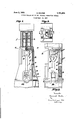
v A construction according to the invention is illustrated by way of example in the accompanying drawing, in which Figure 1 shows an end elevation, partly in section,
Figure 2 a front elevation and Figure 3 a cross section on the line 33 of F i ure 1.
In the example illustrated the invent on is shown applied to an internal combustion engine having a cylinder j in which operates a piston connected at I: to the cross-head g, which in turn is operated by the connectlng rod Z, from a crank-shaft m. The piston is cooled by a circulation of water orother cooling fluid which is supplied to andwithdrawn from the piston through inlet and outlet conduits as follows: One of each pair of telescopic members a with the air vessel 6 is arranged in the interior of the lower portion of the hollow-enginestandard a so as to be separated K from the interior of the engine by the wall n.
The other telescopic tubes d, which are guided in stuffing boxes 6 of the telescopic casings a, are secured to a supporting arm 7 connected to the piston cross head 9 and are provided outside of the engine above the fixed members a. The supporting arm 7 is directed obliquely outwards in such a manner that the slot it, through which its end passes into the standard, is situated in the lateral wall of the latter, that is to say in a wall parallel to the transverse axial plane of the cylinder in which the connecting rod moves, but shifted laterally; in that way, the escape of splashed oil through the slots is avoided since the passage provided by the wall is directed substantially at right angles to the direction to which oil is'splashed by the connecting rod. The connection of the telescopic tubes 03 to the cooling chamber of the piston is effected 1n the usual manner through'the hollow piston rod or through rising pipes.
Instead of arranging the telescopic casings a in the lower portion of the engine frame or standard, the latter could if desired be constituted to form the telescopic casings, owing to which the construction would be somewhat simplified.
What I claim is: v
1. In an engine, an engine frame, a piston, a cylinder for said piston supported by said engine frame, a connecting rod operably connected to said piston and operating in a transverse plane in said engine frame, liquid circulating tubes for said piston, means 7 supporting said tubes for reciprocating movement with said piston, said engine frame having a slot through. which said means ex-. tends, the slot being arranged in a portion of the engine frame which is substantially parallel with said transverse plane so that the passage through the slot is out of line with Y the splashing of the connecting rod, and stationary liquid conducting means telescopically engaging said tubes.
2. In an engine, an engine frame, a piston, a cylinder for said piston supported by said engine frame, a connecting rod operably connected to said piston and operating in a transverse plane in said engine frame, liquid circulating tubes for said piston, means supporting said tubes exteriorly ofthe engine frame for reciprocating movement with said piston but in a path displaced from the said transverse plane, said engine frame having a slot through which said means extends, said slot being provided in a portion of the engine frame which is considerably displaced from said transverse plane so that oil is not readily splashed through the slot by the connecting rod, and stationary liquid conducting means telescopically engaging said tubes.
3. In an engine, an engine frame, a piston, a cylinder for said piston supported by said engine frame, a connecting rod operably connected to said piston and operating in a transverse plane in saidengine frame. liquid circulating tubes for said piston, means supporting said tubes for reciprocating movement with said piston, but in a direction displaced from the said transverse plane, said engine frame having a slot through which said means extends, arranged in a wall of the engine frame which is substantially parallel with said transverse plane, and stationary liquid conducting means separated from the interior of the engine and provided at the lower portion of the engine frame telescopically engaging said tubes.
4. In an engine, an engine frame, a piston,
a cylinder for said piston supported by said engine frame, a connecting rod operating in a transverse plane, a cross-head operably interconnecting said connecting rod and said piston, inlet and outlet liquid circulating tubes for said piston, a supporting arm for said tubes pro ecting from said cross-head and directed obliquely outwards from the placed from the said transverse plane, said engine frame having a slot through which said arm extends, the slot being arranged in a portion of the engine frame which is substantially parallel with said transverse plane ing said tubes to provide for the inlet and 1 outlet of cooling liquid. In testimony whereof I have aifixed my signature.
. HEINRICH BECKER.
cross-head to support said tubes at points dis;
Applications Claiming Priority (1)
| Application Number | Priority Date | Filing Date | Title |
|---|---|---|---|
| DE1761864X | 1926-10-12 |
Publications (1)
| Publication Number | Publication Date |
|---|---|
| US1761864A true US1761864A (en) | 1930-06-03 |
Family
ID=7742205
Family Applications (1)
| Application Number | Title | Priority Date | Filing Date |
|---|---|---|---|
| US223167A Expired - Lifetime US1761864A (en) | 1926-10-12 | 1927-09-30 | Piston cooling device for internal-combustion engines |
Country Status (1)
| Country | Link |
|---|---|
| US (1) | US1761864A (en) |
Cited By (1)
| Publication number | Priority date | Publication date | Assignee | Title |
|---|---|---|---|---|
| US3633468A (en) * | 1968-11-05 | 1972-01-11 | Ihc Holland Nv | Piston of an internal combustion engine |
-
1927
- 1927-09-30 US US223167A patent/US1761864A/en not_active Expired - Lifetime
Cited By (1)
| Publication number | Priority date | Publication date | Assignee | Title |
|---|---|---|---|---|
| US3633468A (en) * | 1968-11-05 | 1972-01-11 | Ihc Holland Nv | Piston of an internal combustion engine |
Similar Documents
| Publication | Publication Date | Title |
|---|---|---|
| US1844386A (en) | Power unit | |
| US1761864A (en) | Piston cooling device for internal-combustion engines | |
| US1446775A (en) | Ship's motor | |
| GB779631A (en) | Improvements relating to internal combustion engines with opposed pistons | |
| US1759147A (en) | Internal-combustion engine | |
| US2067421A (en) | Cooling apparatus | |
| US2184141A (en) | Fuel economizer for gas engines | |
| US3232283A (en) | Cooler for crankcase oil pan oil | |
| US1749683A (en) | Internal-combustion engine | |
| US1910375A (en) | Internal combustion engine | |
| US1963172A (en) | Internal combustion engine | |
| US2079357A (en) | Internal combustion engine | |
| SU11993A1 (en) | Device for cooling pistons in internal combustion engines | |
| US1915284A (en) | Cooled piston rod for double acting engines | |
| US1267702A (en) | Cooling of pistons. | |
| US1739644A (en) | Double-acting motor | |
| US2387344A (en) | Internal-combustion engine | |
| US2271163A (en) | Aircraft construction | |
| US1180878A (en) | Water-cooled piston. | |
| US1298744A (en) | Engine. | |
| US1748807A (en) | Cooling of reciprocating pistons | |
| US2024209A (en) | Machine cooling apparatus | |
| US3230943A (en) | Arrangement for cooling the piston of an internal combustion engine by a liquid coolant | |
| US3179092A (en) | Scavenging air cooler | |
| US930473A (en) | Piston-connecting rod. |