US1761839A - Absorption refrigerating machine - Google Patents
Absorption refrigerating machine Download PDFInfo
- Publication number
- US1761839A US1761839A US113445A US11344526A US1761839A US 1761839 A US1761839 A US 1761839A US 113445 A US113445 A US 113445A US 11344526 A US11344526 A US 11344526A US 1761839 A US1761839 A US 1761839A
- Authority
- US
- United States
- Prior art keywords
- piston
- liquid
- boiler
- slides
- pistons
- Prior art date
- Legal status (The legal status is an assumption and is not a legal conclusion. Google has not performed a legal analysis and makes no representation as to the accuracy of the status listed.)
- Expired - Lifetime
Links
- 238000010521 absorption reaction Methods 0.000 title description 14
- 239000007788 liquid Substances 0.000 description 33
- QGZKDVFQNNGYKY-UHFFFAOYSA-N Ammonia Chemical compound N QGZKDVFQNNGYKY-UHFFFAOYSA-N 0.000 description 15
- 239000006096 absorbing agent Substances 0.000 description 15
- 230000009102 absorption Effects 0.000 description 13
- 238000004891 communication Methods 0.000 description 12
- 230000001105 regulatory effect Effects 0.000 description 9
- 229910021529 ammonia Inorganic materials 0.000 description 7
- 238000005086 pumping Methods 0.000 description 3
- XLYOFNOQVPJJNP-UHFFFAOYSA-N water Substances O XLYOFNOQVPJJNP-UHFFFAOYSA-N 0.000 description 3
- PEDCQBHIVMGVHV-UHFFFAOYSA-N Glycerine Chemical compound OCC(O)CO PEDCQBHIVMGVHV-UHFFFAOYSA-N 0.000 description 2
- 238000001816 cooling Methods 0.000 description 2
- 238000013016 damping Methods 0.000 description 2
- 230000000694 effects Effects 0.000 description 2
- 210000003739 neck Anatomy 0.000 description 2
- 239000003507 refrigerant Substances 0.000 description 2
- 241000272470 Circus Species 0.000 description 1
- 241000543381 Cliftonia monophylla Species 0.000 description 1
- 238000005452 bending Methods 0.000 description 1
- 229940090045 cartridge Drugs 0.000 description 1
- 150000001768 cations Chemical class 0.000 description 1
- 230000006835 compression Effects 0.000 description 1
- 238000007906 compression Methods 0.000 description 1
- 238000010276 construction Methods 0.000 description 1
- 239000000498 cooling water Substances 0.000 description 1
- 230000001419 dependent effect Effects 0.000 description 1
- 229960005150 glycerol Drugs 0.000 description 1
- 235000011187 glycerol Nutrition 0.000 description 1
- 238000007689 inspection Methods 0.000 description 1
- 239000002184 metal Substances 0.000 description 1
- 230000000717 retained effect Effects 0.000 description 1
- 230000035939 shock Effects 0.000 description 1
Images


Classifications
-
- F—MECHANICAL ENGINEERING; LIGHTING; HEATING; WEAPONS; BLASTING
- F25—REFRIGERATION OR COOLING; COMBINED HEATING AND REFRIGERATION SYSTEMS; HEAT PUMP SYSTEMS; MANUFACTURE OR STORAGE OF ICE; LIQUEFACTION SOLIDIFICATION OF GASES
- F25B—REFRIGERATION MACHINES, PLANTS OR SYSTEMS; COMBINED HEATING AND REFRIGERATION SYSTEMS; HEAT PUMP SYSTEMS
- F25B15/00—Sorption machines, plants or systems, operating continuously, e.g. absorption type
- F25B15/10—Sorption machines, plants or systems, operating continuously, e.g. absorption type with inert gas
-
- Y—GENERAL TAGGING OF NEW TECHNOLOGICAL DEVELOPMENTS; GENERAL TAGGING OF CROSS-SECTIONAL TECHNOLOGIES SPANNING OVER SEVERAL SECTIONS OF THE IPC; TECHNICAL SUBJECTS COVERED BY FORMER USPC CROSS-REFERENCE ART COLLECTIONS [XRACs] AND DIGESTS
- Y02—TECHNOLOGIES OR APPLICATIONS FOR MITIGATION OR ADAPTATION AGAINST CLIMATE CHANGE
- Y02A—TECHNOLOGIES FOR ADAPTATION TO CLIMATE CHANGE
- Y02A30/00—Adapting or protecting infrastructure or their operation
- Y02A30/27—Relating to heating, ventilation or air conditioning [HVAC] technologies
-
- Y—GENERAL TAGGING OF NEW TECHNOLOGICAL DEVELOPMENTS; GENERAL TAGGING OF CROSS-SECTIONAL TECHNOLOGIES SPANNING OVER SEVERAL SECTIONS OF THE IPC; TECHNICAL SUBJECTS COVERED BY FORMER USPC CROSS-REFERENCE ART COLLECTIONS [XRACs] AND DIGESTS
- Y02—TECHNOLOGIES OR APPLICATIONS FOR MITIGATION OR ADAPTATION AGAINST CLIMATE CHANGE
- Y02B—CLIMATE CHANGE MITIGATION TECHNOLOGIES RELATED TO BUILDINGS, e.g. HOUSING, HOUSE APPLIANCES OR RELATED END-USER APPLICATIONS
- Y02B30/00—Energy efficient heating, ventilation or air conditioning [HVAC]
- Y02B30/62—Absorption based systems
Definitions
- ABSORPTION REFRIGERATING MACHINE Filed June 5, 1926 3 Sheets-Sheet 3 Fly/a flizdem Johanl jrson Muntm Patented June 3, 1930 UNITED STATES PATENT OFFICE AiTDERS J'OHAN E: SON HUNTERS, F STOCKHOLM; SWEDEN ABSORPTIdN REFBIGERATIN G MACHINE Application filed June 3, 1926, Serial No. 113,445, and in Sweden July 10, 1925.
- the invention refers to absorption refrigerating machines of the continuously operating type and more particularly to refrigerat- 1 mg machines of this kind in which the liquid is circulated by means of a'mechanic-al circulating device arranged to be driven by power generated within the machine.
- Re frigerating machines of this type must generally be hermetically closed, and for this purpose all parts of the machine are soldered together.
- Fi l is apartial sectional View representing diagrammatically an absorption refrigerating machine provided with a circu lating device according to the invention.
- Fig. 2 is a front view of this circulating device, the cover of the same being removed.
- Figs. 3 and 4 show, on a larger scale, the mechanism for effecting a momentary shifting of the regulating slides into different positions.
- Figs. 7 and 8 show a'tightening means for the slides, drawn to a'larger scale.
- Fig. 9 shows a device for the control of the speed of movement of the driving pistons. Another embodiment of the circulating device.
- the machine consists substantially of a boiler 1, a condenser 2, a water separator 3 inserted between the boiler and the condenser, a refrigerator-4, an absorber 5, a heat exchanger 6 to exchange heat between liquid discharged from the boiler and liquid supplied thereto, and of a liquid-conveying or -circulating device 7 inserted between the
- the object of the present in- Fig. 10 shows.
- said circulating device serving to convey the liquid refrigerant from the condenser to the refrigerator, and to transfer absorption liquid from the boiler to the absorber and from the absorber back into the boiler.
- the circulating device 7 which, for the sake of greater clearness, is shown in Fig. 1 to a larger scale than the other parts of the machine, consists substantially of a parallelopipedical metal block 8 forming a piston housing adapted to house two pistons 11, 12 arranged within abore stopper 9.
- the piston 11 which is of a smaller diamaeter than the piston 12, is movable within a bore hole in the stopper 9, whereas the piston 12 is movable within a sleeve 13 prohole 10 closed by a vided'in the bore hole 10.
- a recess l5 Provided between -the piston housing 8 and a cover 14 screwed fast thereto is a recess l5adapted to receive two regulating slides 16 and 17 connected with one another by means of members 18, 19 hooking into each other.
- the two slides 16, 17 may also be integral, but by the said arrangement a link connection is obtained, whereby bending strains and friction consequent thereto is avoided on'the movement of the slides.
- the slides may be momentarily shifted into two different regulating positions by means of the pistons 11, 12 and a mechanism connected thereto, which is shown to a larger scale in Figs. 3 to 6.
- the pistons 11, 12 are connected with one another and with the'said mechanism by means of a forked 'arm 20 adapted to engage the ends of the pistons.
- each piston is provided with a head'21 and 22 respectively and with asmaller neck, while the fork 20 is provided with slots 23, Fig. 5, intb which the piston ends are adapted to enter with their necks, but which are narrower than the heads so that the pistons are retained at the fork.
- the arm 20 constitutes a portion of a car riage 24 the shape of which will be seen. from Figs. 3 to 5 and which is adapted to be displaced in a recess 25 between the cover 14 and the piston housing 8. Inserted between the end. portions 26, 27 of the slide is a pressure spring 28 surrounding a narrower portion 29 of the slide 16. Secured to the part 29 are two pins 30, 31, Figs. 5- and 6, adapted on the movement of the slide to pass freely through recesses in the end portions of the slide and forming stopabutments for the pressure spring.
- the pistons 11, 12 are actuated y aspring 46 bearing on the one side on the stopper 9 and on the other side on the arm 20 of the carriage 24, said spring having a relatively small tension as compared with the spring 28.
- the spring 46 serves substantially only to absorb part'of the pressure .on' the piston 12.
- the slide 16 is provided with two regulating openings 49, 50 adapted to regulate the connection between the piston chamber 47 on the one hand and, on the other hand, a pipe 51 extending from the condenser and a pipe 52 leading to the refrigerator.
- the slide 17 is in a similar way provided with four regulating openings 53, 54, 55, 56 of which the opening 53 controls the connection between the piston chamber 48 on the one hand and, on the other hand, a pipe 57 extending from the heat exchanger 6 anda pipe'58 leading to the absorber.
- the openings 54, 55 and 56 control the connections between a'sluice' chamber 58 in the piston housing-8 on the one hand and a number of pipes59, 60, 61 and 62 on, the other'hand,
- tightening rings 63 Figs. 7 and 8, about the said channels .64, 65 in concentrically arranged annular grooves.
- Said tightening rings 63 which are provided with accurately ground tightening surfaces, are pressed against the slides by means of resilient rings 66 provided in the bottom of said annular grooves, said The rings 63 are preferably provided on their inner sides with an annular tightening abutment 67.
- the absorber and the heat exchanger consistof pipe coils.
- the condenser and the absorb- .er are in known manner provided with a cooling jacket 68 to eifect'cooling by means of cooling water.
- the heat exchanger 6 con-- sists of two pipes 69, 70 arranged concentrically Within one another, through which pipes absorption liquid is caused toflow in counter current in known manner.
- the boiler is intended to be heated by means of a heat cart-ridge 71. It is assumed that the machine operates withammonia as a refrigerating medium and with water as an absorp tion liquid. On its way toward the condenser 2, the ammonia separated in the boiler 1 flows through the water separator 3 in which steam is condensed. The ammonia condensed inthe slide occupies drawing, flow unthe piston cham the condenser will, when the position shown in the der a high pressure into her 47 through the regulating opening and a channel 72 provided in the piston housing. The pistons 11 and 12 are then forced downwards, as hereinbefore described, to
- the evaporated ammonia enters the lower portion of the absorber through a pipe 75.
- the sluice chamber 58 as in the When the slide 17 is'then shifted into its upper position, the lower portion of the sluice chamber 58 is connected through the opening 56 and the pipe 61 with the upper portion 01 the boiler, while at the same time the upper portion of the sluice chamber 58 is brought into communication with the gas space of the boilerthrough the opening 55 and the' pipe 60. The liquid contained in the sluice chamber 58 will consequently flow through the pipe 61 over to the boiler. In this way the enriched liquid will be sluiced back into the boiler, while solution low in ammonia is at the same time transferred in gaged quaniston chamber 48.
- a throttle valve 77 By means ofwhich the resistance of flow of the liquid may be regulatedr
- the said throttle valve may. be replaced, if desired, by a liquid damping device, for instance, of the type shown in Fig. 9.
- a liquid damping device for instance, of the type shown in Fig. 9.
- the pumping efiect proper becomes superfluous, however, if the liquid outlet'is placed at so low a level with respect to the 15 piston chambers 47 and 48 that the liqu d 1s permitted to be discharged by its own welght.
- the position of the circulating device is, in the embodiment described, dependent on the boiler in such a manner that the sluice chamber 58 must be situated above the level of the liquid in the boiler.
- the piston housing 8 has provided therein a further piston 81 adapted to be operated by means ofvapor from the boiler, and by which the liquid rich inammonia is pumped back into ,the boiler.
- the piston 81 which has the form of a differential piston, is adapted to be controlled by the slide 17 which, for this purpose, is pro-' vided with regulating openings 82, 83, 84, 85,-
- the piston 81 will be subjected to a downwardly directed excess pressure, whereb-ythe piston is forced down into its lowermost extreme position in which the piston remains until the slide 17 is shifted into its lower position in the manner hereinbefore described.
- the piston chamber 86 is thus put into communication with the absorber through the opening 82, while the piston chamber 87 is put into communication with. the inner pipe coil of the heat exchanger through the opening 83 and a channel 92 in the piston housing as well as through the pipe 62.
- the piston chamber 88 is brought into communication with the gas space of the boiler through the opening 84 and a channel 93 1n the plston housing as well as through the pipe 90.
- piston is now forced upwardsby the excess pressure of the boiler acting on the narrower end of the piston 81, enriched absorption liquid being then caused to flow from the heat exchanger into the piston chamber 87.
- The. amount of liquid received in the piston chamber 87 is then transferred to the boiler through the pipe 91 after the slide 17 has been shifted into 'its upper position, inasmuch as the pressure of the vapour in the boiler is then 10 may be modified in such a manner that the slides 16, 17 are adapted, instead. to receive their motion from the piston 81 through the medium of a mechanism of the type illustrated in Figs. 3 to 5, the pistons 11, 12 then only having for their object to serve as a means for transferring the liquid in a direction-from the high pressure section of the machine to the low pressure section thereof.
- the-pistons 11, 12 may, if desired, be replaced by sluice chambers of a definite volume corresponding to the maximum volume of the piston chambersv 47, 48, which areal-' 7 ternately brought into communication with the high pressure and the low pressure sections of the machine through the slides 16, 17 in a manner similar to that desci'ib'edwith reference to said piston chambers 47, 48..
- An absorption refrigerating machine having a mechanical circulating device arranged to'be driven by means of power generated wlthm the machine, characterized by all the pipes connecting the circulating device with other parts of the machine being con nected up to a cover plate of the housin'gof the circulating device, to which cover-plate the said housing is. detachably secured so as toallow the latter to be removed without changing the pipe connections.
Landscapes
- Engineering & Computer Science (AREA)
- Physics & Mathematics (AREA)
- Mechanical Engineering (AREA)
- Thermal Sciences (AREA)
- General Engineering & Computer Science (AREA)
- Sorption Type Refrigeration Machines (AREA)
Description
3 Sheets-Sheet 1 Filed June 3, 1926 A. J. E. MUNTERS ABSORPTION REFRIGERATING MACHINE June 3, 1930.
flfforney.
June 3, 1930. A. J. E. MUNTERS ABSORPTION REFRIGERATING MACHINE 3 Sheets-Sheet 2 Filed June 5. 1926 fltorr ey.
' fire/do)". w .flnders Johan fl-sonflunfer June 3, 1930. A. J. E. MUNTERS 1,761,839
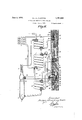
ABSORPTION REFRIGERATING MACHINE Filed June 5, 1926 3 Sheets-Sheet 3 Fly/a flizdem Johanl jrson Muntm Patented June 3, 1930 UNITED STATES PATENT OFFICE AiTDERS J'OHAN E: SON HUNTERS, F STOCKHOLM; SWEDEN ABSORPTIdN REFBIGERATIN G MACHINE Application filed June 3, 1926, Serial No. 113,445, and in Sweden July 10, 1925.
The invention refers to absorption refrigerating machines of the continuously operating type and more particularly to refrigerat- 1 mg machines of this kind in which the liquid is circulated by means of a'mechanic-al circulating device arranged to be driven by power generated within the machine. Re frigerating machines of this type must generally be hermetically closed, and for this purpose all parts of the machine are soldered together. r v
It is, however, desirable, when using a mechanical circulating device, that the latter should be readily accessible for inspection when required.
vention is to provide a construction whereby it may be "possible to dismount the circulating device without any change of the soldered pipe connections. For this purpose allthe pipes connecting the circulating device with other parts of the machine are connected up to a cover'plate of the housing of the circulating device, to which cover plate the said housing is detachably secured so that the circulating device may be dismounted by unfastening the housing from the cover plate. The invention will be described more fully with reference to the accompanying drawings. Fi l is apartial sectional View representing diagrammatically an absorption refrigerating machine provided with a circu lating device according to the invention. Fig. 2 is a front view of this circulating device, the cover of the same being removed. Figs. 3, 4, 5 and 6 show, on a larger scale, the mechanism for effecting a momentary shifting of the regulating slides into different positions. Figs. 7 and 8 show a'tightening means for the slides, drawn to a'larger scale. Fig. 9 shows a device for the control of the speed of movement of the driving pistons. another embodiment of the circulating device. The machine consists substantially of a boiler 1, a condenser 2, a water separator 3 inserted between the boiler and the condenser, a refrigerator-4, an absorber 5, a heat exchanger 6 to exchange heat between liquid discharged from the boiler and liquid supplied thereto, and of a liquid-conveying or -circulating device 7 inserted between the The object of the present in- Fig. 10 shows.
boiler and the condenser on the one side and the refrigerator and the absorber on the other side, said circulating device serving to convey the liquid refrigerant from the condenser to the refrigerator, and to transfer absorption liquid from the boiler to the absorber and from the absorber back into the boiler.
The circulating device 7 which, for the sake of greater clearness, is shown in Fig. 1 to a larger scale than the other parts of the machine, consists substantially of a parallelopipedical metal block 8 forming a piston housing adapted to house two pistons 11, 12 arranged within abore stopper 9. The piston 11 which is of a smaller diamaeter than the piston 12, is movable within a bore hole in the stopper 9, whereas the piston 12 is movable within a sleeve 13 prohole 10 closed by a vided'in the bore hole 10. Provided between -the piston housing 8 and a cover 14 screwed fast thereto is a recess l5adapted to receive two regulating slides 16 and 17 connected with one another by means of members 18, 19 hooking into each other. The two slides 16, 17 may also be integral, but by the said arrangement a link connection is obtained, whereby bending strains and friction consequent thereto is avoided on'the movement of the slides. The slides may be momentarily shifted into two different regulating positions by means of the pistons 11, 12 and a mechanism connected thereto, which is shown to a larger scale in Figs. 3 to 6. The pistons 11, 12 are connected with one another and with the'said mechanism by means of a forked 'arm 20 adapted to engage the ends of the pistons. For this'purpose, each piston is provided with a head'21 and 22 respectively and with asmaller neck, while the fork 20 is provided with slots 23, Fig. 5, intb which the piston ends are adapted to enter with their necks, but which are narrower than the heads so that the pistons are retained at the fork.
The arm 20 constitutes a portion of a car riage 24 the shape of which will be seen. from Figs. 3 to 5 and which is adapted to be displaced in a recess 25 between the cover 14 and the piston housing 8. Inserted between the end. portions 26, 27 of the slide is a pressure spring 28 surrounding a narrower portion 29 of the slide 16. Secured to the part 29 are two pins 30, 31, Figs. 5- and 6, adapted on the movement of the slide to pass freely through recesses in the end portions of the slide and forming stopabutments for the pressure spring. This latter is adapted to bear normally, that is to say, in the one or the other extreme position of the slide, against the end'portions through the medium of washers 32, 33 provided on the part 29, the pins 30, 31 being then in the recesses in the end portions of the slide immediately adjacent the washers. Pivotally mounted on two studs 34, 35 screwed into the piston housing 8 and projecting into the recess 25 are two pawls 36, 37, Figs. 1 and 2, adapted to cooperate with abutments 38, 39 on the two slides. The pawls 36, 37 are actuated by leaf springs 40, 41 tending to keep the pawls in engagement with the abutments 38, 39. However, the pawls may be brought out of operative position through the influence of pins 42,
43 provided on the one lateral wall of the carriage 24, the said pins during the movement of the carriage actuating arms 44, 45 on the (pawls, so that the pawl, which is operative, for the time being, is brought out of operative position, whilethe other pawl is at the same time released so as-to be brought into operoccupy the position shown in Figs. 1 to 5, the
ative position by the appertaining spring or 41 res ectively. The pistons 11, 12 are actuated y aspring 46 bearing on the one side on the stopper 9 and on the other side on the arm 20 of the carriage 24, said spring having a relatively small tension as compared with the spring 28. The spring 46 serves substantially only to absorb part'of the pressure .on' the piston 12. The mechanism operates in the following manner:
- When the pistons 11, 12 and the carriage 24 slides are locked in their one extreme position by the pawl 36 bearing on the abutment 38' of the slide 16. Then in this position of the parts the liquid refrigerating medium flows into the piston chamber 47 in a manner to be described hereinbelow, the pistons are forced downwards, together with the carriage 24,
against the influence of the spring 28, which latter is then compressed between the pin 31 and the upper end portion of the carriage, as shown in Fig. 6. During this movement the pawl 36 is displaced by degrees from its locking position by the pin 42, while the pawl 37 is released by the pin 43. At the end of the piston stroke the slides 16,- 17 aresuddenly released from the position in which they are locked by the pawl 36, and are mo-.
mentarily shifted into their opposite-extreme position under the influence of the spring 28 which is now in a state of compression, in which latter extreme position the spring 28 is, as before, held between the two end walls of the carriage 24, whereas the pins 30, 31 are relieved of the spring' pressure and are situated in the respective recesses in the end walls of the carriage immediately adjacent the washers 32, 33. Consequently, the slides will be stopped in their movement by the pin striking against the washer 32, the spring 28 then acting as a buffer spring damping the shock. In the new position, the slides are locked by the pawl 37 being carried by the spring 41 pertaining thereto into locking position in front of the abutment 39 on the slide 17. By the shifting of the slides the supply of liquid to the piston chamber 47 is cut off, while the piston chamber 48 is simultaneously brought into communication with the liquid space of the boiler. Through the influence of the absorption liquid entering the piston chamber 48,-the pistons 11 and 12 are now'forced back, together with the carriage 24, against the action of. the spring 28 which is now compressed-between the lower end wall 27 of the carriage and the pin 30. During the upward movement of the pistons and the carriage, the slides 16, 17 will be locked by the pawl 37, as set forth. When the pistons reach their upper extreme position, the pawl 37 is moved by the pin 43 out of its locking position, the slides being then momentarily shifted through the influence of the spring 28 into their upper position in which they are again locked by the pawl 36.
The slide 16 is provided with two regulating openings 49, 50 adapted to regulate the connection between the piston chamber 47 on the one hand and, on the other hand, a pipe 51 extending from the condenser and a pipe 52 leading to the refrigerator. The slide 17 is in a similar way provided with four regulating openings 53, 54, 55, 56 of which the opening 53 controls the connection between the piston chamber 48 on the one hand and, on the other hand, a pipe 57 extending from the heat exchanger 6 anda pipe'58 leading to the absorber. The openings 54, 55 and 56 control the connections between a'sluice' chamber 58 in the piston housing-8 on the one hand and a number of pipes59, 60, 61 and 62 on, the other'hand,
bring about the necessary tightening effect.
between the slides and the channels in the piston housing and the cover14 opening adjacent the slides, there are provided tightening rings 63, Figs. 7 and 8, about the said channels .64, 65 in concentrically arranged annular grooves. Said tightening rings 63, which are provided with accurately ground tightening surfaces, are pressed against the slides by means of resilient rings 66 provided in the bottom of said annular grooves, said The rings 63 are preferably provided on their inner sides with an annular tightening abutment 67.
'The refrigerator as well as the condenser,
the absorber and the heat exchanger consistof pipe coils. The condenser and the absorb- .er are in known manner provided with a cooling jacket 68 to eifect'cooling by means of cooling water. The heat exchanger 6 con-- sists of two pipes 69, 70 arranged concentrically Within one another, through which pipes absorption liquid is caused toflow in counter current in known manner.
In the example illustrated, the boiler is intended to be heated by means of a heat cart-ridge 71. It is assumed that the machine operates withammonia as a refrigerating medium and with water as an absorp tion liquid. On its way toward the condenser 2, the ammonia separated in the boiler 1 flows through the water separator 3 in which steam is condensed. The ammonia condensed inthe slide occupies drawing, flow unthe piston cham the condenser will, when the position shown in the der a high pressure into her 47 through the regulating opening and a channel 72 provided in the piston housing. The pistons 11 and 12 are then forced downwards, as hereinbefore described, to
- their opposite extreme position in which the 1 chamber 48 has been brought into slides 16, 1,7 are shifted, the piston chamber 47 being then put into communication with the refrigerator 4 through the regulating opening 49. At the same time, the piston cationwith the liquid space of the boiler through the opening 53, the pipe 57 and the outer pipe coil 70 of the heat exchanger. By reason of this, liquid low in ammonia will now flow into the piston chamber 48through channels 73, 74 arranged in the piston housing 8. Consequently, the pistons 11, 12 will be forced upwards, whereby the liquid ammonia" contained in the piston chamber 47 will be emptied into the refrigerator 4-where the ammonia is evaporated in known manner.
The evaporated ammonia enters the lower portion of the absorber through a pipe 75.
a When the pistons'll, 12 reach their upper again been condenser through the opening 50, by reason position, the slides 16, 17 are shifted anew,
the piston chamber 48 being then brought into,
communication with the upper portion of the absorber through the opening 58, while the supply of liuqid from the boiler is cut off. At the same time the piston chamb'er'47-has put into communication with the of which the pistons'are again caused to move Z downwards. The liquid contained in the piston chamber 48 isthen pressed through the pipe 58 into the upper portion: of'the ab sorber. The quantity of liquid thus transferred from the boiler to the absorber is ngw tities to the absorber through the communiflowing down through the absorber while absorbing ammonia, after which the liquid thus enriched continues to flow into the heat exchanger 6 through a pipe 76.
Return of the enriched liquid to the boiler is effected through the sluice chamber 58 in' the following manner. When the slide 17 is in its lower position, the sluice chamber 58 communicates through the opening in the slide with the pipe 62 extending from the heat exchanger. At the same time the upper portion of the sluice chamber communicates through the opening 54 and the pipe 59 with liquid is caused to assume the same level in.
the sluice chamber 58 as in the When the slide 17 is'then shifted into its upper position, the lower portion of the sluice chamber 58 is connected through the opening 56 and the pipe 61 with the upper portion 01 the boiler, while at the same time the upper portion of the sluice chamber 58 is brought into communication with the gas space of the boilerthrough the opening 55 and the' pipe 60. The liquid contained in the sluice chamber 58 will consequently flow through the pipe 61 over to the boiler. In this way the enriched liquid will be sluiced back into the boiler, while solution low in ammonia is at the same time transferred in gaged quaniston chamber 48. The mutual relationship between the volumes of the piston chambers 47 and 48 is so adapted that the right proportion is obtained between circulating refrigerant and absorption liquid. Through the arrangement described said proportion will obviously remain constant during operation. To attain this result, it is not necessary that the pistons 11, 12-be interconnected. It is of importance, only, that the regulating members16, 17. adapted to control their movement are arranged to operate in synchronism.
To control the operating frequency of the pistons, thereis inserted into the channel 74 a throttle valve 77, by means ofwhich the resistance of flow of the liquid may be regulatedr The said throttle valve may. be replaced, if desired, by a liquid damping device, for instance, of the type shown in Fig. 9. According to this embodiment, there is attached to the end of the piston 12, another piston '78 adapted to move within a. closed cyhlder 79 filled with a liquid such as glyc erine, the piston having a port 80 so adapted as to provide a suitable resistanceof-motion.
In the embodiment above described, the
transfer of liquid takes place ina direction from the high pressure section to the low pressure section, as well as in the opposite direction, by means of devices operating on the principle of a liquid sluice, inasmuch as the piston chambers 47 and 48 and the slldes 16, 17 are alternately brought into communi- 5 cation with vessels of difierent pressures. In the example shown, however, the pistons 11 and 12 work at the same time as pumppistons, so that the transfer of liquid in a direction from the high pressure section to the low pressure. section is, in fact, taking place through a combined pumping and slulcing action. The pumping efiect proper becomes superfluous, however, if the liquid outlet'is placed at so low a level with respect to the 15 piston chambers 47 and 48 that the liqu d 1s permitted to be discharged by its own welght. However,by utilizing the pumping effect, one will be independent of the position of the circulating device relatively to the refrigeratorand the absorber. On the other hand, the position of the circulating device is, in the embodiment described, dependent on the boiler in such a manner that the sluice chamber 58 must be situated above the level of the liquid in the boiler.
In the embodiment shown in Fig. 10, the
arrangements are such that the circulating device may be brought into any position desired with respect to the other parts of the machine. To this end, the piston housing 8 has provided therein a further piston 81 adapted to be operated by means ofvapor from the boiler, and by which the liquid rich inammonia is pumped back into ,the boiler.
The piston 81, which has the form of a differential piston, is adapted to be controlled by the slide 17 which, for this purpose, is pro-' vided with regulating openings 82, 83, 84, 85,-
through which the piston chambers may be alternately brought into communication with the boiler and the absorber through the medium of pipes 89, 90 and 91. The mode of operation is as follows:
When the slide occupies the upper position indicated in the drawing, the piston chamber communicates through the opening 83 with the gas space of the boiler. When in this position of the slide the piston chamber 87 ,is
also in communication with the gas space of the boiler through the opening 84, while the piston chamber 88 communicates with the absorber through the opening 85, the piston 81 will be subjected to a downwardly directed excess pressure, whereb-ythe piston is forced down into its lowermost extreme position in which the piston remains until the slide 17 is shifted into its lower position in the manner hereinbefore described. The piston chamber 86 is thus put into communication with the absorber through the opening 82, while the piston chamber 87 is put into communication with. the inner pipe coil of the heat exchanger through the opening 83 and a channel 92 in the piston housing as well as through the pipe 62. At the same time the piston chamber 88 is brought into communication with the gas space of the boiler through the opening 84 and a channel 93 1n the plston housing as well as through the pipe 90. The
piston is now forced upwardsby the excess pressure of the boiler acting on the narrower end of the piston 81, enriched absorption liquid being then caused to flow from the heat exchanger into the piston chamber 87. The. amount of liquid received in the piston chamber 87 is then transferred to the boiler through the pipe 91 after the slide 17 has been shifted into 'its upper position, inasmuch as the pressure of the vapour in the boiler is then 10 may be modified in such a manner that the slides 16, 17 are adapted, instead. to receive their motion from the piston 81 through the medium of a mechanism of the type illustrated in Figs. 3 to 5, the pistons 11, 12 then only having for their object to serve as a means for transferring the liquid in a direction-from the high pressure section of the machine to the low pressure section thereof. If the piston 81 is thus arranged to drive the slides, the- pistons 11, 12 may, if desired, be replaced by sluice chambers of a definite volume corresponding to the maximum volume of the piston chambersv 47, 48, which areal-' 7 ternately brought into communication with the high pressure and the low pressure sections of the machine through the slides 16, 17 in a manner similar to that desci'ib'edwith reference to said piston chambers 47, 48..
I claim: t 1. An absorption refrigerating machine having a mechanical circulating device arranged to'be driven by means of power generated wlthm the machine, characterized by all the pipes connecting the circulating device with other parts of the machine being con nected up to a cover plate of the housin'gof the circulating device, to which cover-plate the said housing is. detachably secured so as toallow the latter to be removed without changing the pipe connections.
2, In absorption refrigerating machines having a mechanical circulating device ar ranged to be driven by means of power generated within the machine, the combination of a housing for said circulating device a cover for said housing, pipes connecting the circu-v lating device with other parts of the machine v and connected up to said cover plate, said housing detachably secured to said cover plate, so as to allow the latter to be removed without changing the pipe connections, slidable control means disposed between the cover 5 plate and the housing and adapted to control the communication between the said pipes and the circulating device.
In testimony whereof I aflix my signature. ANDERS J OHAN E SON MUN TERS. l0
Applications Claiming Priority (1)
| Application Number | Priority Date | Filing Date | Title |
|---|---|---|---|
| SE1761839X | 1925-07-10 |
Publications (1)
| Publication Number | Publication Date |
|---|---|
| US1761839A true US1761839A (en) | 1930-06-03 |
Family
ID=20423510
Family Applications (1)
| Application Number | Title | Priority Date | Filing Date |
|---|---|---|---|
| US113445A Expired - Lifetime US1761839A (en) | 1925-07-10 | 1926-06-03 | Absorption refrigerating machine |
Country Status (1)
| Country | Link |
|---|---|
| US (1) | US1761839A (en) |
-
1926
- 1926-06-03 US US113445A patent/US1761839A/en not_active Expired - Lifetime
Similar Documents
| Publication | Publication Date | Title |
|---|---|---|
| US1761839A (en) | Absorption refrigerating machine | |
| JPH0660770B2 (en) | Heat driven heat pump | |
| US2383486A (en) | Refrigeration mechanism | |
| US3693370A (en) | Thermodynamic cycles | |
| US2930204A (en) | Refrigerator | |
| US3526102A (en) | Pumping and cooling system | |
| EP0215659B1 (en) | Improvements in and relating to systems which use an absorption refrigeration cycle | |
| US2583285A (en) | Hydraulic piston-control rigging for refrigerator-compressors | |
| US2484669A (en) | Method and device relating to absorption refrigerating apparatus | |
| US3141307A (en) | Absorption refrigeration apparatus | |
| GB786519A (en) | Improvements in absorption refrigerating machines | |
| US2366955A (en) | Refrigeration | |
| US3041847A (en) | Compressor capacity controllers | |
| US3539277A (en) | Bellows pump | |
| US2009372A (en) | Automatic low temperature ice system | |
| US2146077A (en) | Refrigeration | |
| US1905308A (en) | Refrigerating system | |
| US3101597A (en) | Gas refrigerator | |
| US2339811A (en) | Absorption refrigerator | |
| US1707319A (en) | Refrigerating device | |
| US2196777A (en) | Refrigerant expansion control | |
| US2393241A (en) | Intermittent absorption or adsorption refrigerating apparatus | |
| GB255035A (en) | Improvements in or relating to absorption refrigerating machines | |
| US932946A (en) | Refrigerating apparatus. | |
| GB301941A (en) | Improvements in absorption refrigerating machines |