US1761815A - Side bearing for railway cars - Google Patents
Side bearing for railway cars Download PDFInfo
- Publication number
- US1761815A US1761815A US244875A US24487528A US1761815A US 1761815 A US1761815 A US 1761815A US 244875 A US244875 A US 244875A US 24487528 A US24487528 A US 24487528A US 1761815 A US1761815 A US 1761815A
- Authority
- US
- United States
- Prior art keywords
- spring
- car
- bearing
- truck
- springs
- Prior art date
- Legal status (The legal status is an assumption and is not a legal conclusion. Google has not performed a legal analysis and makes no representation as to the accuracy of the status listed.)
- Expired - Lifetime
Links
- 230000003068 static effect Effects 0.000 description 5
- 206010012411 Derailment Diseases 0.000 description 4
- 238000006563 Carroll rearrangement reaction Methods 0.000 description 3
- 238000005266 casting Methods 0.000 description 3
- 229910000831 Steel Inorganic materials 0.000 description 2
- 230000009471 action Effects 0.000 description 2
- 230000000994 depressogenic effect Effects 0.000 description 2
- 239000002184 metal Substances 0.000 description 2
- 229910052751 metal Inorganic materials 0.000 description 2
- 239000007787 solid Substances 0.000 description 2
- 239000010959 steel Substances 0.000 description 2
- 229910001018 Cast iron Inorganic materials 0.000 description 1
- 235000006629 Prosopis spicigera Nutrition 0.000 description 1
- 240000000037 Prosopis spicigera Species 0.000 description 1
- 230000002159 abnormal effect Effects 0.000 description 1
- 230000008901 benefit Effects 0.000 description 1
- 239000003245 coal Substances 0.000 description 1
- 230000006835 compression Effects 0.000 description 1
- 238000007906 compression Methods 0.000 description 1
- 238000010276 construction Methods 0.000 description 1
- 238000005242 forging Methods 0.000 description 1
- 230000005484 gravity Effects 0.000 description 1
- 238000003754 machining Methods 0.000 description 1
- 239000000463 material Substances 0.000 description 1
- 230000004048 modification Effects 0.000 description 1
- 238000012986 modification Methods 0.000 description 1
- 230000002265 prevention Effects 0.000 description 1
- 238000000926 separation method Methods 0.000 description 1
Images

Classifications
-
- B—PERFORMING OPERATIONS; TRANSPORTING
- B61—RAILWAYS
- B61F—RAIL VEHICLE SUSPENSIONS, e.g. UNDERFRAMES, BOGIES OR ARRANGEMENTS OF WHEEL AXLES; RAIL VEHICLES FOR USE ON TRACKS OF DIFFERENT WIDTH; PREVENTING DERAILING OF RAIL VEHICLES; WHEEL GUARDS, OBSTRUCTION REMOVERS OR THE LIKE FOR RAIL VEHICLES
- B61F5/00—Constructional details of bogies; Connections between bogies and vehicle underframes; Arrangements or devices for adjusting or allowing self-adjustment of wheel axles or bogies when rounding curves
- B61F5/02—Arrangements permitting limited transverse relative movements between vehicle underframe or bolster and bogie; Connections between underframes and bogies
- B61F5/14—Side bearings
Definitions
- ATTORNEY 45 its steel Patented June 3, 1930 -UNrn STATES PATENT oFFlcE CHARLES R. BUSCH, OF ORANGE, NEW JERSEY, ⁇ ASSIGrNOR TO BUFFALO BRAKE COMPANY, OF NEW YORK, N. Y., A CORPORATION OF NEW YORK sinn BEARING non RAILWAY CARS Application filed January 6, 1928. Serial No. 244,875.
- the objects of the invention are to overcome faults inherent in present day railway cars and which result in derails and serious accidents, and not to overcome deway car when in service moving along a track has a tendency to roll or sway sidewise, which tendency isespecially apparent when the car is approaching curves or is leaving them, or when the car is moving on a track which is not in the best condition, as
- the present railway car is also a rigid car because of construction, its extreme height above the'rails, and its high capacity as with a coal car.
- the vcenter of gravity of the present railway car is many feet above the Vtrucks of the carso that this fact also tends to cause side-swayf-when the car is iny motion, which motion is aggravated by the high speeds at which the cars are run.
- One of the objects of the present invention is to provide aside bearing which is located on the truck bolster or truck frame, or the body bolster or transom, or the combination of both, so as to act as an equalizer to the body and/or load and the car truck, and which side bearing has spring means for preventing roll or side-sway of the car body,
- the improved side bearing also has additional spring means to absorb and equalize the static load and to normalize the car body with the trucks on uneven tracks, curves and the like, while the car is in motion, so that the static load is removed from the truck springs, the journal bearings, and the wheel flanges, thereby effecting a saving in these parts of the car.
- the combination of such spring means in a side bearing insures traction of the wheels on the light side of the car, when it rolls or sways sidewise to thus throw all the weight on one side of the car. While the bearing on the heavy side compresses to yaccept the heavy load,V
- Figure 1 is a longitudinal sectional view, partly in elevation, of the improvedside bearing showing the same applied and in normal position
- Fig. 2. is aftransverse section/thereof
- Y Fig. l-3 is a plan ofthe side bearing
- Fig. 4 is an -elevation ofthe side bearin provided with a bearing roller;
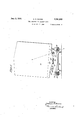
- Fig. 5 is an elevation of ya ⁇ railway car on track and which is V'provided with the pres-v ent improvements, the body of the car being shown as swayed sidewise but the wheels staying put on the two track-rails. l
- the truck bolster or frame 10 and the rigid bearing casting 11 of the body bolster or transom' are illustrated partially, the casting 11 having a chan'g plate or surface 12 of hard steel.
- the bolster or frame 10 forms the bottom wall of the base member 18 of a housing ⁇ or casting of the side bearing which includes a top or cap member'14.
- the base member 13 has a reinforced flange 15 through which extend fastenings 16, preferably in the form of rivets, and these also extend through the bolster .or frame 10 and rigidly and permanently mount the housing in the desired position, on the truck in the present instance.
- the housing section or base member 13 is provided with an inward shoulder 17 (see kalso Fig. 3) at that edge which Vis -spaced away Yfrom the bolster or frame 10,
- f ⁇ nclo'sed in the housing 13, 114 are yat least In the extremeAY tions.
- the other spring 23 is also laminated 'and comprises semi-,elliptic leaves 24, 25,26, 27 and 28 assembled kface to face,
- the described ⁇ spring deviceo-r unit is asvsembled'in the housing before the sidebearing is "permanently fixed position, the
- a free, clearance space B0 separates the surface 31 'ofthe uniti'ngfband 29 from 'the adjacent surface of the truck bolster or frame and a Vfree clearance space '32 1 also separates the ⁇ 'opposite surface of theband from the surj face 33' of the cap member.
- the chafi Ving plate 12v preferably Ymoves on a dove-4 vtailed;inse-rt 14 ⁇ in the cap member 14, the .sard'insert being composed 'of vwear resisting Y
- the primary 1 land secondary springs of the two-fold :spring devlce may now perform their duties Y.
- the part-s illustrated comprise the following: bolster or frame 37 of car truck 38; truck springs 39 and 40; ⁇ car body 41; body bolster 42 center wear plates 43, ⁇ 44; and the improved side bearings 45, 46.
- the carbody Y has rolled or swayed sidewise and that the bearings at each side maintain a working relation (with no clearance) with the car body, and vthat due to the improvements the wheels at both sides of the truckremain in running contact withl both rails of the ear track, for reasons now to beexplained.
- the purpose of the primary spring 19, Figs. 1 and 2 is to compress when the body 41 ofthe car (Fig. 5) is placed on the trucks 38, of which one is shown, in order to bring the center wear plates 43, 45, in vbearing relation with the side bearings 45, 46, in such a manner as tov allow no clearance between the wear plates and the side bearings; and saidprimary spring is made in such manner as to allow free turning radius to the trucks.
- The" object is to preventY roll or side sway of the car body becausethere is no such clearance.
- An incidental advantage is, that machining of the center plates vand side bearings is eliminated, and that wear on the center plates of the body and trucks will be compensated for.
- the object ofthe lessv resilient secondary spring 23 is to absorb and equalize the static 4described insures traction of the wheels on thelight side of the car when the car side Vsw'ays or rolls solasto throw all the weight on one side ⁇ of the car las 'shown in Fig. 5, inasmuch as the side bearing on the heavy fsideis causedftokcompress the heavier secondary spring 23 as shown in broken lines, Fig. 2, to accept theheavy load, while the bearing at the Vother side of the truck expands proportionately and its springs exert present condition of car derailments.
- the side bearing on the light side ofthe car "i expands it follows the chaiing plate 12 at a downward pressure in excess of the weight of the truck thereunder, thus insuring trac tion as shown in Fig. 5, and avoiding the f LS that side as is maintained in contact with it due to the combined actions of the side bearings at both sides of the truck.
- the line X indicates that of the static load, and points out very clearly that when a car rolls or side sways, the truck springs at the heavy side of a car provided with the Vimproved side bearings are save d and are Vthe binding member of the springs being of given thickness allowing the binding member to carry the ⁇ overload without permitting the spring leaves to be strainedto the imit'of elasticity and lose their life by going Obviously the invention is susceptible to a widerange of modification by those skilled yin the art without departing from the spirit of the invention as defined inthe appended claims. l
- a two-fold spring device comprising a primary laminated spring and a secondary laminated spring of less resiliency than the primary spring, the two springs being arranged ⁇ for mutual opposition, and the primary spring serving as a cushion for excess weights and the secondary spring serving to maintain a permanent bearing relation between the side bearing and the car body.
- a two-fold spring device comprising a primary laminated spring and a secondary lammaryv springY and assembled as air-@unitary inated spring of less resiliency 'pridevice, the two springs being arranged for mutual opposition, and the primary spring serving as a cushion for excess weights and the secondary spring serving to maintain a permanent bearing relation between the side [bearing and the car body.
- each springliaving Vfree ends having a sliding engagement with y their ownv bearing surface, andeach spring comprising semi-,elliptic leaves curved reversely to the leaves of the other., and a uniting b'and binding the two springstogether, the two springs being arrangedfor mutual opposition.
- a housing comprising a base member and a cap member which are Vmovand comprising aV primary springand a secondary spring of less resiliency than the primary spring, the two springs being arranged for mutual opposition.
- a housing comprising a basev member anda ,cap member which are movable relatively toeach other, and a two-fold spring device arrangedY in the housing and comprising ai primaryspring and a secondary spring of less resiliency thanthe c primary spring, the two springs beings-var- Y ranged for direct mutual opposition.
- a housing comprising a base member and a cap member which are movable relatively to y each otherwand agtwoposition.
- a housing comprising abase .member and a'cap membery which are movable relatively to each other, and a two-fold Y ,so of the other, the two springs being arranged Y i0. in .a Side bearing for railway Cars, the
- each spring comprising semi-elliptic leaves curved reversely vto the' being arranged for mutual'opposition.
- a 'housing comprising a base member-and al cap memberfwhich are movable relativelyl to each other and stop means Vfor the outward limitI of movement'of the two members, and a springl unit Varranged vin the housing and including a primary, laminated, semi-elliptic spring and a secondary, laminated, semi-elliptic spring of K less resiliency thanthe primary spring, one
- a housing comprising abase member and a-cap member which are movc.
- combination of a housing comprising a base member and-a cap member which are movable relatively to each other and stop means for theY outward limit of movement of the two members, and primary and secondary springs of relatively different resiliency within the housing, and being in mutual opposition, the primary spring bearing upon the base member and the secondary spring upon the cap member, the springs including semi-elliptic leaves curved away from each other, and means uniting the springs and providing abutments against the base member and cap member respectively.
- a frame member of the truck anda frame member of the body of the car in combination, a frame member of the truck anda frame member of the body of the car, and side bearing means interposed between such frame members, and including a primary spring Vand a rsecondary spring of less resiliency than the primary spring, and assembled as a unitary device, the two springs being arranged in mutual'opposition, and respectively mechanically functioning one with closer proximity to the body frame-member and the other with closer proximity to the truckl frame-member, vfor substantially the purposes ,set forth.
- a frame member of the truck and a frame member of the body of the car comprising a housing including a base member fixed to the truck frame member, a cap member having cooperative relation with the body frame-member, the base and cap members movable relatively to each other, a spring unit arranged in the housing and including a primary laminated, semi-elliptic spring bearing upon the base member and a secondary, laminated, semi-elliptic spring of less resiliency than the primary spring and bearing upon the cap member, the'two springs being arranged in mutual opposition and curved outwardly with respect to each other.
- a frame member of the truck and a frame member of the body of the car comprising a housing including a base member fixed tothe truck frame members, a cap member having cooperative relation with the body frame-member, the base and cap members movable relatively to each other, a spring unit arranged in the housing and including va primary, laminated, semi-elliptic spring bearing upon the base member and a secondary, laminated, semi-elliptic spring of less resiliency than the primary spring and bearing upon the cap member, the two springs being arranged in mutual opposition and curved outwardly with respect to each other and means for precluding separation of the base member and cap member.
- each side bearing including a base and a cap, together with a two-fold spring device located between' the base and cap, the spring device comprising a primary spring and a secondary spring of less resil-y iency than the primary spring and urging the cap to maintain a permanent bearing relation with the corresponding chafing plate, whereby wear takes place on the center plates without causing any abnormal weight to rest on the side bearings so that the car
Landscapes
- Engineering & Computer Science (AREA)
- Mechanical Engineering (AREA)
- Springs (AREA)
Description
June 3, 1930. c; R. BUSCH SIDE BEARINGvFOR RAILWAY CARS Filed Jan. 6, 1928 2 Sheets-Sheet l ATTORNEY IIHHHHM lin . rin.
June 3, 1930. c. R. BUSCH SIDE BEARING FOR RAILWAY CARS Filed Jan. 6. 1928 2 Sheets-Shea?I 2 INVENTOR BEf/A/nfs R z/.szw
ATTORNEY 45 its steel Patented June 3, 1930 -UNrn STATES PATENT oFFlcE CHARLES R. BUSCH, OF ORANGE, NEW JERSEY, `ASSIGrNOR TO BUFFALO BRAKE COMPANY, OF NEW YORK, N. Y., A CORPORATION OF NEW YORK sinn BEARING non RAILWAY CARS Application filed January 6, 1928. Serial No. 244,875.
contribute very largely indeed to the life of the truck springs in service and to a more perfectand satisfactory action of the truck springs because, on therone hand, the irnproved side bearings have a tendency to 1e overcome the dangerous set liable to occur in truck springs while on the other hand they relieve,l equalize and reduce the sudden thrusts or loads toy which truck springs are frequently subjected, and in both cases contribute to the safety and lives of railway employees as well as passangers.
At the Vpresent time there is a great lack Y of basic information pertaining to the prevention of derailments of railway cars and 2o to the relation of car wheel loads to track stresses, and while the present invention does not supply the complete answer to thesev matters, it is believed to provide in a large meas; ure a quite complete means for overcoming many of the difliculties for which satisfactory answers have not been found. Let it be Vnoted that the objects of the invention are to overcome faults inherent in present day railway cars and which result in derails and serious accidents, and not to overcome deway car when in service moving along a track has a tendency to roll or sway sidewise, which tendency isespecially apparent when the car is approaching curves or is leaving them, or when the car is moving on a track which is not in the best condition, as
-where low` rail joints are prevalent and where the tracks are soft, and on account of the rail joints being staggered.v The present railway car is also a rigid car because of construction, its extreme height above the'rails, and its high capacity as with a coal car. The vcenter of gravity of the present railway car is many feet above the Vtrucks of the carso that this fact also tends to cause side-swayf-when the car is iny motion, which motion is aggravated by the high speeds at which the cars are run. The entire load of the body of the car and its contents are carried on a center plate upon each truck, the load being more or less balanced on each side of the center plate by two side bearings (two to each truck) which are now used on all cars of different designs, but all of these side bearings work only with a clearance. This clearance however slight also allows the car 'to more great! ly roll or sway sidewise, and, when the bearings come in contact with any part of the car-body, to immediately transfer the load to the truck springs, so that these are broken, or in most cases go solid, that is,
caused to partake of a set. When solid truck sprin s occur the load becomes static and is trans erred from the center plate to a point beyond and outside the wheels. The opposite side bearing being out of contact withy the load, the opposite wheels rise up from their rails in a tipping motion, and when the car rolls back .the said opposite wheels may not engage their rails, thus causing derailment of the car or broken truck parts.
One of the objects of the present invention is to provide aside bearing which is located on the truck bolster or truck frame, or the body bolster or transom, or the combination of both, so as to act as an equalizer to the body and/or load and the car truck, and which side bearing has spring means for preventing roll or side-sway of the car body,
because there is no clearance between the side bearing and the body or between it and the truck, as the case may be.
The improved side bearing also has additional spring means to absorb and equalize the static load and to normalize the car body with the trucks on uneven tracks, curves and the like, while the car is in motion, so that the static load is removed from the truck springs, the journal bearings, and the wheel flanges, thereby effecting a saving in these parts of the car. The combination of such spring means in a side bearing insures traction of the wheels on the light side of the car, when it rolls or sways sidewise to thus throw all the weight on one side of the car. While the bearing on the heavy side compresses to yaccept the heavy load,V
I ment of the invention, in which:
Figure 1 is a longitudinal sectional view, partly in elevation, of the improvedside bearing showing the same applied and in normal position,
Fig. 2. is aftransverse section/thereof,
partly in elevation, showing the side bearing in two other positions, one position in full lines and the other position in broken lines;
Y Fig. l-3 is a plan ofthe side bearing;
Fig. 4 is an -elevation ofthe side bearin provided with a bearing roller; v
Fig. 5 is an elevation of ya `railway car on track and which is V'provided with the pres-v ent improvements, the body of the car being shown as swayed sidewise but the wheels staying put on the two track-rails. l
Referring to Figs. 1 and 2, the truck bolster or frame 10 and the rigid bearing casting 11 of the body bolster or transom' are illustrated partially, the casting 11 having a chan'g plate or surface 12 of hard steel. The bolster or frame 10 forms the bottom wall of the base member 18 of a housing `or casting of the side bearing which includes a top or cap member'14. The base member 13 has a reinforced flange 15 through which extend fastenings 16, preferably in the form of rivets, and these also extend through the bolster .or frame 10 and rigidly and permanently mount the housing in the desired position, on the truck in the present instance.
The housing section or base member 13 is provided with an inward shoulder 17 (see kalso Fig. 3) at that edge which Vis -spaced away Yfrom the bolster or frame 10,
while the cap member`14 has at its adjacent edgean outward shoulder 1S,.tl1e cap member in this case telescoping in the base member 18 and being guided inwardly and outwardly by reason of its shoulder 18 having Aa sliding bearing relation with the inner surface of the base member. l'outwzird posit-ion of the" cap member the shoulder 18` abut-s `againstthe shoulder 17, vand 'thuskthe cap member is limited in its outward movement Vand cannot separate from the lbase member. The abutting *relation'of these two shoulders is illustratedjin.
f `nclo'sed in the housing 13, 114, are yat least In the extremeAY tions. v
rorder named. The other spring 23 is also laminated 'and comprises semi-, elliptic leaves 24, 25,26, 27 and 28 assembled kface to face,
and which also gradually decrease in length, 1n the order named.` There isa Vgreater number of' leaves tospring'23, and each of these 1 j leaves is thicker and hence less liexible or resilent than the leaves of the spring 19. Y
Y It will be :observed that the curvature` of each spring 19, 23, is away from the other spring and that they adjacent leaves of the vsprings have a mutual bearing relation and opposition with eachother, the two springs being firmly and permanently united together in such relationshipby means of a strong, l encircling, metal .band 29 preferably sov .in the formr of a'metal forging which is shrunk or swcated onto 'the springs so .as to unite them as a spring unit, to be enclosed as a whole 1n the housing of the side bearing.
The described `spring deviceo-r unit is asvsembled'in the housing before the sidebearing is "permanently fixed position, the
ends of the longest leaf 24-ofV spring 23 being first inserted in the housing so that they7 may bear upon the inner surface vof thecap 'member 14 whereas the Vends kof the longest leaf '20of spring 19 will bear upon the truck bolster orL frame 10 when the housing is fastened 'in the desired position. In Fig. 1, the" free height of `the cap member 14v is Vshown `before the Vcar body is lapplied to the truck, Vthat is vthe springs are shown as fully expanded, and subsequently herein -the spring 19 will 'be termed thefprimary spring andithe spring 23 the secondary spring. Y
f To permit the primary and secondary springs to accomplishtheir respective and v combined ymechanical functions they are fully expanded and a free, clearance space B0, as shownin'Fig. 1, separates the surface 31 'ofthe uniti'ngfband 29 from 'the adjacent surface of the truck bolster or frame and a Vfree clearance space '32 1also separates the` 'opposite surface of theband from the surj face 33' of the cap member.
`:and vnew -will'first be described. The chafi Ving plate 12v preferably Ymoves on a dove-4 vtailed;inse-rt 14`in the cap member 14, the .sard'insert being composed 'of vwear resisting Y The primary 1 land secondary springs of the two-fold :spring devlce may now perform their duties Y.
jin the improved. sidefbearing, and the V120` material, for instance` cast iron. Furthermore, to reducewear and friction caused `by constant contact with the ch'afing plate,
car. The part-s illustrated comprise the following: bolster or frame 37 of car truck 38; truck springs 39 and 40; `car body 41; body bolster 42 center wear plates 43, `44; and the improved side bearings 45, 46. In this figure it will be observed that the carbody Y has rolled or swayed sidewise and that the bearings at each side maintain a working relation (with no clearance) with the car body, and vthat due to the improvements the wheels at both sides of the truckremain in running contact withl both rails of the ear track, for reasons now to beexplained.
The purpose of the primary spring 19, Figs. 1 and 2, is to compress when the body 41 ofthe car (Fig. 5) is placed on the trucks 38, of which one is shown, in order to bring the center wear plates 43, 45, in vbearing relation with the side bearings 45, 46, in such a manner as tov allow no clearance between the wear plates and the side bearings; and saidprimary spring is made in such manner as to allow free turning radius to the trucks. The" object is to preventY roll or side sway of the car body becausethere is no such clearance. An incidental advantage is, that machining of the center plates vand side bearings is eliminated, and that wear on the center plates of the body and trucks will be compensated for. When the body is placed'on the trucks, the lcap member 12 will be depressed as shown in Fig. 2 and the primary spring 19 compressed until ,the
` The object ofthe lessv resilient secondary spring 23 is to absorb and equalize the static 4described insures traction of the wheels on thelight side of the car when the car side Vsw'ays or rolls solasto throw all the weight on one side` of the car las 'shown in Fig. 5, inasmuch as the side bearing on the heavy fsideis causedftokcompress the heavier secondary spring 23 as shown in broken lines, Fig. 2, to accept theheavy load, while the bearing at the Vother side of the truck expands proportionately and its springs exert present condition of car derailments.
the side bearing on the light side ofthe car "i expands it follows the chaiing plate 12 at a downward pressure in excess of the weight of the truck thereunder, thus insuring trac tion as shown in Fig. 5, and avoiding the f LS that side as is maintained in contact with it due to the combined actions of the side bearings at both sides of the truck.
What ordinarily happens at the present time when a car rolls or side sways is, that the truck is tipped as well as the body of the car, the truck springs being compressed at the heavy side and the truck springs at the light side of the car being expandedf80 and the center wear plates being subjected to increased load, and the body bearings at the depressed side of the car being forced unduly against the usual side bearing, while the body bearing at the lifted side of the car is not bearing at all on the opposite side bearing but is separated therefrom by considerable clearance, thus lifting the wheels at that side of the car off from'their rail and encouraging derailment of the car. In Fig. 5 the line X indicates that of the static load, and points out very clearly that when a car rolls or side sways, the truck springs at the heavy side of a car provided with the Vimproved side bearings are save d and are Vthe binding member of the springs being of given thickness allowing the binding member to carry the` overload without permitting the spring leaves to be strainedto the imit'of elasticity and lose their life by going Obviously the invention is susceptible to a widerange of modification by those skilled yin the art without departing from the spirit of the invention as defined inthe appended claims. l
What I claim as new and of my invention is:
1. In a side bearing for railway cars, a two-fold spring device comprising a primary laminated spring and a secondary laminated spring of less resiliency than the primary spring, the two springs being arranged `for mutual opposition, and the primary spring serving as a cushion for excess weights and the secondary spring serving to maintain a permanent bearing relation between the side bearing and the car body.
2. In a side bearing for railway cars, a two-fold spring device comprising a primary laminated spring and a secondary lammaryv springY and assembled as air-@unitary inated spring of less resiliency 'pridevice, the two springs being arranged for mutual opposition, and the primary spring serving as a cushion for excess weights and the secondary spring serving to maintain a permanent bearing relation between the side [bearing and the car body.
3. Ink a side bearing for railway cars, bearing surfaces, and a two-fold spring device located-between and bearing on such surfaces, and comprising a primary spring and a secondaryspring of-lessv resiliency n than the primary spring, each spring having free ends having 'a sliding engagement with their own bearing surface, and each'spring comprising semi-elliptic leaves curved reversely to the leaves of the other, the two Yprings being arrangedfor mutual opposition. f
t. In a side bearing foryrailwayfcars, bearing surfaces, and a two-fold spring devicel located between and bearing on such surfaces,^and comprising a primary spring and a secondary springl of `less resiliency than the primary-spring, each springliaving Vfree ends having a sliding engagement with y their ownv bearing surface, andeach spring comprising semi-,elliptic leaves curved reversely to the leaves of the other., and a uniting b'and binding the two springstogether, the two springs being arrangedfor mutual opposition.
5. In a side bearing for railwaycars, the combination of a housing comprising a base member and a cap member which are Vmovand comprising aV primary springand a secondary spring of less resiliency than the primary spring, the two springs being arranged for mutual opposition. 4
7. VIna side bearing orrailway cars,'the
combination of a housing comprising a basev member anda ,cap member which are movable relatively toeach other, and a two-fold spring device arrangedY in the housing and comprising ai primaryspring and a secondary spring of less resiliency thanthe c primary spring, the two springs beings-var- Y ranged for direct mutual opposition.
8. In a sidebearing orrailway cars',fthey combination of a housingcomprising a base member and a cap member which are movable relatively to y each otherwand agtwoposition.
',within the housing, 'and being in mutuallopposition, the` primary spring bearing upon fold springrdevice arranged in the housing device, the two Vsprin mutual opposition.
9. In aside Vbearing for railwaycars, thev,
combination of a housingcomprising a base l and comprising a primary spring and-a secf ondary spring of less resiliency than the primary spring, and-assembled as a unitary I gsV being arranged ory y member and a cap member which are movable relatively to each other, and a two-foldV spring devicearranged in thechousingy and vcomprisinga primaryspring and aiseeondary springof lesspresiliency than the pri` i mary spring, feach spring vcomprising semielliptic leaves curved reversely to vthe leaves for mutual opposition.
combination of a housing comprising abase .member and a'cap membery which are movable relatively to each other, and a two-fold Y ,so of the other, the two springs being arranged Y i0. in .a Side bearing for railway Cars, the
spring device arranged in Athe lhousing and comprising aV primary spring vand a secondaryspring ofl less rresiliency than the primary spring, each spring comprising semi-elliptic leaves curved reversely vto the' being arranged for mutual'opposition. y
1l. In a side bearing-for railway cars, the' combination of a 'housing comprising a base member-and al cap memberfwhich are movable relativelyl to each other and stop means Vfor the outward limitI of movement'of the two members, and a springl unit Varranged vin the housing and including a primary, laminated, semi-elliptic spring and a secondary, laminated, semi-elliptic spring of K less resiliency thanthe primary spring, one
lspring curved oppositely to the other, and
means vfor uniting the springs.
12. In a side bearingfor railway cars, the A I combination of a housing comprising a base ablerelatively-to each other and stop means);vr
'leaves ofthe other, and auniting band b indi. .ing the twosprings together, the two springs y' member and a cap member which are mov- ,Y v 1l() for the, outward limit of movement-of theft s two members,jand a' two-:told spring-'dev'ficek arrangedinthe housing and comprising Ya Y primary spring and asecondary spring off' less resiliency than the primaryspring, thcri twosprings beinggarranged for'. mutual op-`l 13.v In a side bearingforv railway cars,1the i.
combination of a housing comprising abase member and a-cap member which are movc.
Iablerelatively to each other and stop means for the voutward limit of `movement of the y.-two members, and primary and secondary springs of relatively different resiliency* the' base member and the"v secondary spring uponthe capmember."Y
"14. In aside bearingforrailway cars, thejj f combination of a housing comprisinga base upon the cap member, and means to prevent the springs when under extreme compression from developing a set.
15. In a side bearing for railway cars, the
. combination of a housing comprising a base member and-a cap member which are movable relatively to each other and stop means for theY outward limit of movement of the two members, and primary and secondary springs of relatively different resiliency within the housing, and being in mutual opposition, the primary spring bearing upon the base member and the secondary spring upon the cap member, the springs including semi-elliptic leaves curved away from each other, and means uniting the springs and providing abutments against the base member and cap member respectively.
16.In a railway car, in combination, a frame member of the truck and a frame member of the body of the car and side bearing means interposed between such frame members, and including a primary spring and a secondary spring of less resiliency than the primary spring, the two springs being arranged in mutual opposition, and respectively mechanically functioning one with closer proximity to the body framemember and the other with closer proximity to the truck frame-member, for substantially the purposes set forth.
17. In av railway car, in combination, a frame member of the truck anda frame member of the body of the car, and side bearing means interposed between such frame members, and including a primary spring Vand a rsecondary spring of less resiliency than the primary spring, and assembled as a unitary device, the two springs being arranged in mutual'opposition, and respectively mechanically functioning one with closer proximity to the body frame-member and the other with closer proximity to the truckl frame-member, vfor substantially the purposes ,set forth. v
18. vIn a railway car, in combination, a frame member of the truck and a frame y member of the bodyof the car, andside bearing means interposed between such frame members, and including a primary spring and a secondary spring of less resiliency than the primary spring, each spring comprising semi-elliptic leaves curved reversely yto the leaves of the other, the two springs beingy arranged in mutual opposi tion, and respectively mechanically functioning one with closer proximity to the body frame-member and the other with closer proximity to the truck frame-member, for substantially the purposes set forth.
19. In a railway car, in combination, a frame member of the truck and a frame member of the body of the car, and side bearing means interposed between such frame members, and comprising a housing including a base member fixed to the truck frame member, a cap member having cooperative relation with the body frame-member, the base and cap members movable relatively to each other, a spring unit arranged in the housing and including a primary laminated, semi-elliptic spring bearing upon the base member and a secondary, laminated, semi-elliptic spring of less resiliency than the primary spring and bearing upon the cap member, the'two springs being arranged in mutual opposition and curved outwardly with respect to each other.
20. In a railway car, in combination, a frame member of the truck and a frame member of the body of the car, and side bearing means interposed between such frame members, and comprising a housing including a base member fixed tothe truck frame members, a cap member having cooperative relation with the body frame-member, the base and cap members movable relatively to each other, a spring unit arranged in the housing and including va primary, laminated, semi-elliptic spring bearing upon the base member and a secondary, laminated, semi-elliptic spring of less resiliency than the primary spring and bearing upon the cap member, the two springs being arranged in mutual opposition and curved outwardly with respect to each other and means for precluding separation of the base member and cap member.
21. In a railway car, in combination, the truck, the car body, expansible side bearings fixed to one of them, bearings having chang plates and fixed rigidly to the other of them, center plates supporting the body upon the truck, each side bearing including a base and a cap, together with a two-fold spring device located between' the base and cap, the spring device comprising a primary spring and a secondary spring of less resil-y iency than the primary spring and urging the cap to maintain a permanent bearing relation with the corresponding chafing plate, whereby wear takes place on the center plates without causing any abnormal weight to rest on the side bearings so that the car
Priority Applications (1)
| Application Number | Priority Date | Filing Date | Title |
|---|---|---|---|
| US244875A US1761815A (en) | 1928-01-06 | 1928-01-06 | Side bearing for railway cars |
Applications Claiming Priority (1)
| Application Number | Priority Date | Filing Date | Title |
|---|---|---|---|
| US244875A US1761815A (en) | 1928-01-06 | 1928-01-06 | Side bearing for railway cars |
Publications (1)
| Publication Number | Publication Date |
|---|---|
| US1761815A true US1761815A (en) | 1930-06-03 |
Family
ID=22924466
Family Applications (1)
| Application Number | Title | Priority Date | Filing Date |
|---|---|---|---|
| US244875A Expired - Lifetime US1761815A (en) | 1928-01-06 | 1928-01-06 | Side bearing for railway cars |
Country Status (1)
| Country | Link |
|---|---|
| US (1) | US1761815A (en) |
Cited By (5)
| Publication number | Priority date | Publication date | Assignee | Title |
|---|---|---|---|---|
| US2788250A (en) * | 1953-03-11 | 1957-04-09 | Symington Gould Corp | Resilient side bearing |
| US2830857A (en) * | 1948-06-16 | 1958-04-15 | Symington Gould Corp | Side bearing |
| DE1144315B (en) * | 1957-12-04 | 1963-02-28 | Kloeckner Humboldt Deutz Ag | Sealing for the support of the car bodies of rail vehicles on bogies or swivel frames consisting of lateral sliding pieces |
| US3707927A (en) * | 1970-09-28 | 1973-01-02 | Standard Car Truck Co | Resilient truck side bearings |
| EP2916015A1 (en) * | 2014-03-05 | 2015-09-09 | Bombardier Transportation GmbH | Component with reaction force optimised holder, vehicle, and method |
-
1928
- 1928-01-06 US US244875A patent/US1761815A/en not_active Expired - Lifetime
Cited By (5)
| Publication number | Priority date | Publication date | Assignee | Title |
|---|---|---|---|---|
| US2830857A (en) * | 1948-06-16 | 1958-04-15 | Symington Gould Corp | Side bearing |
| US2788250A (en) * | 1953-03-11 | 1957-04-09 | Symington Gould Corp | Resilient side bearing |
| DE1144315B (en) * | 1957-12-04 | 1963-02-28 | Kloeckner Humboldt Deutz Ag | Sealing for the support of the car bodies of rail vehicles on bogies or swivel frames consisting of lateral sliding pieces |
| US3707927A (en) * | 1970-09-28 | 1973-01-02 | Standard Car Truck Co | Resilient truck side bearings |
| EP2916015A1 (en) * | 2014-03-05 | 2015-09-09 | Bombardier Transportation GmbH | Component with reaction force optimised holder, vehicle, and method |
Similar Documents
| Publication | Publication Date | Title |
|---|---|---|
| US3638582A (en) | Resilient bearing mounting | |
| US2053990A (en) | Anti-oscillating device | |
| US775271A (en) | Car-truck. | |
| US4433629A (en) | Railway truck bearing mounting assembly | |
| EA010048B1 (en) | Rail road car truck and members thereof | |
| US2296106A (en) | Radial truck | |
| US3762339A (en) | Railway truck anti-rock side bearing device | |
| US3905305A (en) | Snubbed railway truck bolster | |
| US3359923A (en) | Railway bogie | |
| US1761815A (en) | Side bearing for railway cars | |
| US1979235A (en) | Car truck | |
| US696617A (en) | Car-truck. | |
| US2046391A (en) | Railway car construction | |
| US2272426A (en) | Railway truck structure | |
| US2756691A (en) | Railway vehicle truck | |
| US2797650A (en) | Railway vehicle | |
| US2317398A (en) | Railway truck structure | |
| US2013797A (en) | Lateral motion spring damping car truck | |
| US2051646A (en) | Truck | |
| US2709971A (en) | Rail truck squaring means | |
| US2135728A (en) | Truck | |
| US2088291A (en) | Truck | |
| US2572113A (en) | Railway truck axle box mounting | |
| US700172A (en) | Car-truck. | |
| RU208700U9 (en) | THREE-ELEMENT TROLLEY FOR CARGO CARS |