US1979235A - Car truck - Google Patents
Car truck Download PDFInfo
- Publication number
- US1979235A US1979235A US581253A US58125331A US1979235A US 1979235 A US1979235 A US 1979235A US 581253 A US581253 A US 581253A US 58125331 A US58125331 A US 58125331A US 1979235 A US1979235 A US 1979235A
- Authority
- US
- United States
- Prior art keywords
- journal
- wheels
- brake
- truck
- box
- Prior art date
- Legal status (The legal status is an assumption and is not a legal conclusion. Google has not performed a legal analysis and makes no representation as to the accuracy of the status listed.)
- Expired - Lifetime
Links
- NJPPVKZQTLUDBO-UHFFFAOYSA-N novaluron Chemical compound C1=C(Cl)C(OC(F)(F)C(OC(F)(F)F)F)=CC=C1NC(=O)NC(=O)C1=C(F)C=CC=C1F NJPPVKZQTLUDBO-UHFFFAOYSA-N 0.000 description 24
- 238000010276 construction Methods 0.000 description 14
- 230000009471 action Effects 0.000 description 7
- 230000007246 mechanism Effects 0.000 description 6
- 238000006073 displacement reaction Methods 0.000 description 4
- 230000001788 irregular Effects 0.000 description 4
- 230000003578 releasing effect Effects 0.000 description 4
- 230000027455 binding Effects 0.000 description 3
- 210000005069 ears Anatomy 0.000 description 2
- 230000005484 gravity Effects 0.000 description 2
- 239000002184 metal Substances 0.000 description 2
- 230000008439 repair process Effects 0.000 description 2
- 206010012411 Derailment Diseases 0.000 description 1
- 239000011248 coating agent Substances 0.000 description 1
- 238000000576 coating method Methods 0.000 description 1
- 230000002517 constrictor effect Effects 0.000 description 1
- 230000001419 dependent effect Effects 0.000 description 1
- 239000013013 elastic material Substances 0.000 description 1
- 238000007689 inspection Methods 0.000 description 1
- 230000009191 jumping Effects 0.000 description 1
- 230000003137 locomotive effect Effects 0.000 description 1
- 238000005461 lubrication Methods 0.000 description 1
- 238000012423 maintenance Methods 0.000 description 1
- 230000009467 reduction Effects 0.000 description 1
- 238000005096 rolling process Methods 0.000 description 1
- 239000000725 suspension Substances 0.000 description 1
Images


Classifications
-
- B—PERFORMING OPERATIONS; TRANSPORTING
- B61—RAILWAYS
- B61F—RAIL VEHICLE SUSPENSIONS, e.g. UNDERFRAMES, BOGIES OR ARRANGEMENTS OF WHEEL AXLES; RAIL VEHICLES FOR USE ON TRACKS OF DIFFERENT WIDTH; PREVENTING DERAILING OF RAIL VEHICLES; WHEEL GUARDS, OBSTRUCTION REMOVERS OR THE LIKE FOR RAIL VEHICLES
- B61F5/00—Constructional details of bogies; Connections between bogies and vehicle underframes; Arrangements or devices for adjusting or allowing self-adjustment of wheel axles or bogies when rounding curves
- B61F5/26—Mounting or securing axle-boxes in vehicle or bogie underframes
- B61F5/30—Axle-boxes mounted for movement under spring control in vehicle or bogie underframes
- B61F5/32—Guides, e.g. plates, for axle-boxes
Definitions
- journal boxes each journal box being mounted in a pedestal so as to be guided in position and in its movements by flanges on its sides engaging the pedestal legs, as a result of which the journal box is not free to adjust itself to irregularities in the position of the pedestal and to irregularities in the journal at the same time; as, for instance, if the pedestal flares outwardly or inwardly from a plumb or vertical line the box is required by the guides bearing on the legs of the pedestal to position itself on the journal whichever way the pedestal happens to be attached to the truck.
- One object of my present invention is to provide means for mounting the brake heads in such manner as to permit them to move laterally, with and during any lateral movements of the wheels, and under pressure of the wheel flanges, whereby to always maintain a proper relationship between the brake heads and wheels and prevent any resistance of the brake heads to the lateral movements of the wheels in accommodating themselves to track variations.
- a further object of the invention is to provide for the mounting of the brake heads on an articulated, oscillating, lateral motion car truck so that the brake heads will automatically adjust themselves to a proper working position with relation. to the wheels in the various adjusting movements of the latter.
- the present application shows my improved brake head supports as employed in conjunction with a floating journal box construction in which the journal box is limited in its lateral movements and held from lateral displacement by interlocking connection with cushioned equalizer bearers, as shown in my said application Serial No. 493,426, although it is to be understood that the improved brake head supports may be employed in conjunction with a floating journal box of the type disclosed in my said application Serial No. 285,899, in which the journal box is allowed to have a certain amount of lateral movement but is held from lateral displacement by suitable stop surfaces on the journal box and truck side frames.
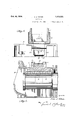
- Fig. 1 is a side elevation, partly in section, of a portion of a truck frame showing a journal box 100 and brake structure embodying my invention.
- Figs. 2, 3 and 4 are vertical transverse sections taken on lines 2-2, 3--3 and 4-4 of Fig. 1.
- Fig. 5 is a sectional plan view of parts shown in Fi 1.
- Fig. 6 is a vertical longitudinal section through the journal box shown in Figs. 1 and 5.
- Fig. '7 is a top plan view of a part of the car truck.
- journal box 5 is a side frame member of the truck frame of a railway passenger car provided with the pedestals 2 having the jaws or legs 3 which may be provided on their inner. faces with wear plates 4.
- This journal box is devoid of the usual guide flanges or other guiding connections at its sides with the pedestal legs, being of a width somewhat less than the distance between the wear plates 4 of the legs and fitted to slide with freedom between the legs, so that it may accommodate itself to irregularities in the position of the pedestal and to irregularities in the journal at one and the same time.
- the pedestal deviates either inwardly ,or outwardly from a plumb or vertical line, or is warped or twisted, this condition of the pedestal ,will not affect the movements of the journal box, which may position itself either vertically or inwardly or outwardly (laterally) with relation to the pedestal and longitudinally on the journal as may be required, dependent upon the position I the pedestal may happen to have upon the truck.
- journal box is also such as to allow the journal box and axle to have radial or pivotal movement to a certain degree longitudinally of the car.
- journal box and pedestal which rub hard against the pedestal legs and prevent free movement of the box between the pedestal legs incident to the action of the cushioning springs and to positioning movements of the wheels on the track rails
- wear and tear upon the journal box and pedestal and upon the wheel flanges and track rails will be prevented and hard or rough riding of the car and track and rail and other binding and constricting actions resisting free travel will be effectually obviated.
- journal box may be provided with wear plates 6' to reduce wear and tear thereon and to provide easy ,contact between the journalbox and the wear plates 6, and if desired, a stop flange 6 may be provided on either side of the box at the rear for engagement with the pedestal to limit the outward movement of the box, when being jacked up to remove and replace journal bearings or journal bearing wedges.
- the journal box 5 may be of the type shown in Figs. 2 and 3 in which the box is provided at .its top with a fixed or integral wedge seat- 7 for the journal bearing 8, disposed between the same and the journal 9, with which seat or wedge and the journal it may have an interlocking connection to assist in holding the box from inward or outward displacement on the journal and relative to the pedestal and journal.
- the box is provided externally at its top with side flanges 10 and front and rear flanges 11, arranged in parallel pairs and to form a pocket or socket for interlocking connection with a depending or deand the journal box and the interlocking connec- I tion between the journal bearing 8 and the seat or wedge 7 and the journal 9, the journal box is held from displacement while permitted to have automatic adjusting and floating movements, thus securing a highly efllcient cushioning action for easy riding and adjustment of the journal boxes with the journals, without binding restriction, to permit the wheels to accommodate themselves to curves and irregularities in the track rails, and frictional wear and tear is reduced to the minimum, giving longer life to the journal boxes and pedestals and obviating the expensive frequent repairs and replacements now necessary incidental to the use of pedestals and journal box mountings of ordinary construction.
- the pocket or socket formed by the flanges 10 and 11 may also serve to receive a cushioning damper of rubber or other elastic material engaged by the end of the bearer l3 and providing a cushioning action for the movement of the bearer, while preventing objectionable grinding noise and wear and tear due to direct contact of metal upon metal.
- the journal box construction disclosed in Figs. 2 and 3 adapts the seat or wedge for the journal bearing to be cast with the roof of the box, thereby eliminating what is commonly known as the journal bearing key, commonly made use of to hold the journal bearing in place and which, as ordinarily constructed, is provided with a radial top to allow adjustment for the journal bearing on the journal, which becomes inoperative because of the wear on the backof the wedge and inside of the top of the journal box and also because of the radius on top of the journal box wedgev wearing flat.
- My construction of the journal box avoids the extra cost of the wedge and eliminates entirely the wear and tear on top and on the inside of the roof of the box when the'wedge is used as a separate piece.
- truck design including the floating journal box, arranged and mounted as set forth, does away with the use of a multiplicity of parts, equal in number to about two hundred pieces per car, avoiding the purchase cost of such items, the inspection requirements, and the maintenance cost, and producing a truck containing less parts subject to damage or breakage and giving easier and quieter riding of the trucks under the car, and doing away largely also with the hazards incident to the use of trucks of ordinary construction containing so many parts liable to cause derailments and other accidents.
- the brake heads 16 are mounted at their upper ends on pivot bolts or members 18 passing through ears on the heads and engaging inclined slots 19 in the fork plates 20 of forked hangers carried by the truck frame, whereby the coupled brake heads, brake beams and shoes are mounted to slide toward and from the wheels in a path inclined to the horizontal, as well as to have pivotal movements to adjust themselves to the'wheels in a braking action.
- the arrangement is such that after application, and upon release of the brake mechanism, the brakes will automatically by their weight or by the action of gravity move away from the wheels dim to the outward and downward inclination of the slots 19.
- the brake heads are mounted for free and automatic adjustments to suit varying'conditions of the brake rigging and wheels in the brake applying and releasing actions, and to recede positively on a brake releasing action so as to prevent the undue wear and tear caused ordinarily by continuance of engagement of the brake shoes with the wheels after a brake releasing action.
- This construction also obviates the use of the ordinary brake hangers, pins and keys and the well known objections incident thereto, such as their tendency to cant and bind so as to inhibit simultaneous free movements of the parts in different planes of the character referred to.
- the ears of the brake beams also slidably engage the pins or bolts 18 so as to be movable between the fork arms 20 laterally of the truck or car, under pressure of the wheel flanges in the lateral shifting movements of the wheels to accommodate themselves to curves or other track variations, so that such adjustments of the wheels can occur without interference therewith by the brake shoes.
- the wheels may freely adjust themselves to track variations, to obtain what I call free-wheeling, thus preventing wheel and track flange wear and resistance to travel of the train.
- my invention provides a truck so constructed that the framework of the erally in the opposite direction.
- my invention provides a truck in which the truck framework may move laterally with the car body in one direction while the wheels and the journal box are moving laterallyv in the opposite direction at the same time, and that this construction will allow one pair of wheels and the associated journal boxes, as well as the associated brake beam, to move laterally in one direction, while the other wheels, journal boxes and brake beams of the same truck may move laterally in the opposite direction.
- My improved'construction also adapts the truck frame to freely move laterally in one direction while the truck bolster is free to move laterally in the opposite direction with the brake beam, car wheels and journal box.
- my invention provides a brake mechanism for articulated, oscillating, lateral motion car trucks in which free lateral and radial movements of the aforesaid parts are permitted, independently or conjointly.
- the truck frame When the car is rounding a curve, the truck frame, with the body, may move laterally in one direction on the curve, while the wheels, journal boxes and brake beams may move simultantously in the opposite direction, thereby relieving the stran on the rails over which the wheels are rolling, the strain of the wheel flanges against the rails and the strain of the brake shoes against the flanges of the wheels, reducing to a minimum train resistance and reduction in the load for the locomotive to pull.
- a truck frame In a running gear and brake mechanism for railway cars, a truck frame, an axle, journal 120 boxes in which the ends of the axle are journaled, said boxes being loosely mounted for floating motion in the truck side frames in such manner as to adapt the axles and boxes and the side frames to have relative vertical, lateral and 125 radial movements, and brake heads mounted directly on the truck and supported thereon for applying and releasing actions and for relative movements vertically, laterally and radially of the truck with the wheels.
- hangers directly mounted on the truck 1335 having fork arms provided with slots inclined to the horizontal, pivot pins slidably engaging said slots, and brake heads supported by the pivot pins for pivotal movements in said slots and sliding movements therein toward and from the wheels, said heads being also slidably mounted on said pins for movement laterally of the frame, whereby the brake heads are mounted to move conjointly with the wheels relatively to the frame laterally and radially as specified.
- Brake mechanism for articulated, oscillating, lateral motion car trucks comprising a truck frame and wheels, movable vertically, laterally and radially with relation to each other, brake III heads directly supported by the truck frame with freedom of motion toward and from the wheels and laterally of the truck frame, and means connecting the heads at opposite sides of the frame to move conjointly with the wheels relatively o the frame laterally and radially as specified.
- brake heads directly supported by the truck frame for sliding movements toward and from the wheels, laterally with relation to the wheels, laterally and radially with the wheels relatively to the frame, and automatic retraction by gravity when braking stress is removed therefrom, and means connecting the brake heads at opposite sides of the frame to move conjointly with the wheels relatively and radially. as specified.
- Brake mechanism for articulated, oscillating, lateral motion brakes comprising a truck frame and wheels Journaled therein; movable to the frame laterally-
Landscapes
- Engineering & Computer Science (AREA)
- Mechanical Engineering (AREA)
- Handcart (AREA)
Description
Oct. 30, 1934. J J TUM CAR TRUCK Filed Dec. 15, l95l 4 Sheets-Sheet l WW/1W "H N N i Oct. 30, 1934. .1. J. TATUM 1,979,235
CAR TRUCK Filed Dec. 15, 1931 4 Sheets-Sheet 2 gwuwnkoz J. J. TATUM Oct. 30, 1934.
CAR TRUCK 4 Sheets-Sheet 3 Filed Dec. 15 1951 gwuento'c Vdttomwug J. J. TATUM Oct. 30, 1934.
CAR TRUCK Filed Dec. 15, 1931 4 Sheets-Sheet 4 A fi M 1 I I I I I I Patented Oct. 30, 1934 UNITED STATES PATENTv OFFICE 5 Claims.
This application is a continuation in part of my prior application for patent filed November 4, 1930, Serial No. 493,426, and applies also to subject-matter disclosed in my application for patent tionship between-the wheels and brake shoes.
Passenger car trucks, as now commonly constructed, are provided with positively guided journal boxes, each journal box being mounted in a pedestal so as to be guided in position and in its movements by flanges on its sides engaging the pedestal legs, as a result of which the journal box is not free to adjust itself to irregularities in the position of the pedestal and to irregularities in the journal at the same time; as, for instance, if the pedestal flares outwardly or inwardly from a plumb or vertical line the box is required by the guides bearing on the legs of the pedestal to position itself on the journal whichever way the pedestal happens to be attached to the truck. This often throws the load carried by the truck on the back end of the journal bearing in the box, or on the front end, resulting in a small bearing area of the journal bearing being overloaded to such an extent that binding between the journal bearing and the journal occurs and oil is prevented from flowing between the bearing and journal for the lubrication of the bearing surfaces Accordingly, what is known as a hot journal occurs, whereby the journal is damaged or burnt off. Furthermore, the guides on the sides of the journal box rub hard against the pedestal legs and prevent free movement of the box between the pedestal legs brought about by the action of the cushioning springs, resulting in hard or rough riding cars. In passenger cars of usual construction there is a further objection, in that the brake beams are mounted upon hangers carried by the truck frame, which mode of mounting does not allow adjustment of the brake shoes to accommodate themselves to changes of position of the wheels, particularly as regards curvatures in the rails, and the hanger suspension often interferes with a proper release of the brake shoes. Hence there is an objectionable amount of wheel flange and track friction and resistance to travel caused because of the inability, due to such friction and resistance, of the brake shoes to adjust themselves to the movements of the wheels in such manner as to relieve such friction and resistance.
One object of my present invention is to provide means for mounting the brake heads in such manner as to permit them to move laterally, with and during any lateral movements of the wheels, and under pressure of the wheel flanges, whereby to always maintain a proper relationship between the brake heads and wheels and prevent any resistance of the brake heads to the lateral movements of the wheels in accommodating themselves to track variations.
A further object of the invention is to provide for the mounting of the brake heads on an articulated, oscillating, lateral motion car truck so that the brake heads will automatically adjust themselves to a proper working position with relation. to the wheels in the various adjusting movements of the latter.
The present application shows my improved brake head supports as employed in conjunction with a floating journal box construction in which the journal box is limited in its lateral movements and held from lateral displacement by interlocking connection with cushioned equalizer bearers, as shown in my said application Serial No. 493,426, although it is to be understood that the improved brake head supports may be employed in conjunction with a floating journal box of the type disclosed in my said application Serial No. 285,899, in which the journal box is allowed to have a certain amount of lateral movement but is held from lateral displacement by suitable stop surfaces on the journal box and truck side frames.
The invention consists of the features of construction, combination and arrangement of parts, 95 hereinafter fully described and claimed, reference being had to the accompanying drawings, in which:--
Fig. 1 is a side elevation, partly in section, of a portion of a truck frame showing a journal box 100 and brake structure embodying my invention.
Figs. 2, 3 and 4 are vertical transverse sections taken on lines 2-2, 3--3 and 4-4 of Fig. 1.
Fig. 5 is a sectional plan view of parts shown in Fi 1.
Fig. 6 is a vertical longitudinal section through the journal box shown in Figs. 1 and 5.
Fig. '7 is a top plan view of a part of the car truck.
In the illustrated embodiment of the invention, no
1 is a side frame member of the truck frame of a railway passenger car provided with the pedestals 2 having the jaws or legs 3 which may be provided on their inner. faces with wear plates 4. In the pedestal 2 between the legs 3 is arranged a floating journal box 5. This journal box is devoid of the usual guide flanges or other guiding connections at its sides with the pedestal legs, being of a width somewhat less than the distance between the wear plates 4 of the legs and fitted to slide with freedom between the legs, so that it may accommodate itself to irregularities in the position of the pedestal and to irregularities in the journal at one and the same time. If, therefore, the pedestal deviates either inwardly ,or outwardly from a plumb or vertical line, or is warped or twisted, this condition of the pedestal ,will not affect the movements of the journal box, which may position itself either vertically or inwardly or outwardly (laterally) with relation to the pedestal and longitudinally on the journal as may be required, dependent upon the position I the pedestal may happen to have upon the truck.
.The spacing between the sides of the journal box and the pedestal legs is also such as to allow the journal box and axle to have radial or pivotal movement to a certain degree longitudinally of the car. By mounting the journal box so that it is free from guiding engagement with the pedestal, the journal box is prevented from being forcibly shifted to throw the load carried by the truck either on the back end of the journal bearing or on the front end of the journal bearing,
and constricting or preventing the flow of oil between the journal bearing and the journal with the result of causing what is known as a hot journal, resulting in the damaging or burning off of the journal. Furthermore, by doing away with the use of positive guiding connections between the journal box and pedestal, which rub hard against the pedestal legs and prevent free movement of the box between the pedestal legs incident to the action of the cushioning springs and to positioning movements of the wheels on the track rails, wear and tear upon the journal box and pedestal and upon the wheel flanges and track rails will be prevented and hard or rough riding of the car and track and rail and other binding and constricting actions resisting free travel will be effectually obviated. As a result,
an easy riding truck or car is obtained, wear and tear and frequent replacement and repairs reduced, and the journal box allowed to float and to thereby have free and unimpeded movements for easier riding actions regardless of any irregularities in the form or condition of the.
pedestal or of the journal being slightly tapered or otherwise irregular. The sides of the journal box may be provided with wear plates 6' to reduce wear and tear thereon and to provide easy ,contact between the journalbox and the wear plates 6, and if desired, a stop flange 6 may be provided on either side of the box at the rear for engagement with the pedestal to limit the outward movement of the box, when being jacked up to remove and replace journal bearings or journal bearing wedges.
The journal box 5 may be of the type shown in Figs. 2 and 3 in which the box is provided at .its top with a fixed or integral wedge seat- 7 for the journal bearing 8, disposed between the same and the journal 9, with which seat or wedge and the journal it may have an interlocking connection to assist in holding the box from inward or outward displacement on the journal and relative to the pedestal and journal. The box is provided externally at its top with side flanges 10 and front and rear flanges 11, arranged in parallel pairs and to form a pocket or socket for interlocking connection with a depending or deand the journal box and the interlocking connec- I tion between the journal bearing 8 and the seat or wedge 7 and the journal 9, the journal box is held from displacement while permitted to have automatic adjusting and floating movements, thus securing a highly efllcient cushioning action for easy riding and adjustment of the journal boxes with the journals, without binding restriction, to permit the wheels to accommodate themselves to curves and irregularities in the track rails, and frictional wear and tear is reduced to the minimum, giving longer life to the journal boxes and pedestals and obviating the expensive frequent repairs and replacements now necessary incidental to the use of pedestals and journal box mountings of ordinary construction. The pocket or socket formed by the flanges 10 and 11 may also serve to receive a cushioning damper of rubber or other elastic material engaged by the end of the bearer l3 and providing a cushioning action for the movement of the bearer, while preventing objectionable grinding noise and wear and tear due to direct contact of metal upon metal.
The journal box construction disclosed in Figs. 2 and 3 adapts the seat or wedge for the journal bearing to be cast with the roof of the box, thereby eliminating what is commonly known as the journal bearing key, commonly made use of to hold the journal bearing in place and which, as ordinarily constructed, is provided with a radial top to allow adjustment for the journal bearing on the journal, which becomes inoperative because of the wear on the backof the wedge and inside of the top of the journal box and also because of the radius on top of the journal box wedgev wearing flat. My construction of the journal box avoids the extra cost of the wedge and eliminates entirely the wear and tear on top and on the inside of the roof of the box when the'wedge is used as a separate piece.
The described construction of truck design including the floating journal box, arranged and mounted as set forth, does away with the use of a multiplicity of parts, equal in number to about two hundred pieces per car, avoiding the purchase cost of such items, the inspection requirements, and the maintenance cost, and producing a truck containing less parts subject to damage or breakage and giving easier and quieter riding of the trucks under the car, and doing away largely also with the hazards incident to the use of trucks of ordinary construction containing so many parts liable to cause derailments and other accidents.
In order to secure proper positioning of the brake heads with relationship to the wheels, and adapt them to accommodate themselves to lateral and other adjustments of the wheels without restriction from the brake gearing, I mount the coating brake head 16 at opposite sides of the truck frame so as to be freely adjustable with their carrier beams 17 toward the peripheries of the wheels and also laterally of and with the wheels. To this end the brake heads 16 are mounted at their upper ends on pivot bolts or members 18 passing through ears on the heads and engaging inclined slots 19 in the fork plates 20 of forked hangers carried by the truck frame, whereby the coupled brake heads, brake beams and shoes are mounted to slide toward and from the wheels in a path inclined to the horizontal, as well as to have pivotal movements to adjust themselves to the'wheels in a braking action. The arrangement is such that after application, and upon release of the brake mechanism, the brakes will automatically by their weight or by the action of gravity move away from the wheels dim to the outward and downward inclination of the slots 19. By this means the brake heads are mounted for free and automatic adjustments to suit varying'conditions of the brake rigging and wheels in the brake applying and releasing actions, and to recede positively on a brake releasing action so as to prevent the undue wear and tear caused ordinarily by continuance of engagement of the brake shoes with the wheels after a brake releasing action. This construction also obviates the use of the ordinary brake hangers, pins and keys and the well known objections incident thereto, such as their tendency to cant and bind so as to inhibit simultaneous free movements of the parts in different planes of the character referred to. As shown in Figs. 2, 3 and 4 the ears of the brake beams also slidably engage the pins or bolts 18 so as to be movable between the fork arms 20 laterally of the truck or car, under pressure of the wheel flanges in the lateral shifting movements of the wheels to accommodate themselves to curves or other track variations, so that such adjustments of the wheels can occur without interference therewith by the brake shoes. By thus mounting the brake heads to move laterally with the wheels, the wheels may freely adjust themselves to track variations, to obtain what I call free-wheeling, thus preventing wheel and track flange wear and resistance to travel of the train.
It will be observed that my invention provides a truck so constructed that the framework of the erally in the opposite direction.
Also it will be seen that my invention provides a truck in which the truck framework may move laterally with the car body in one direction while the wheels and the journal box are moving laterallyv in the opposite direction at the same time, and that this construction will allow one pair of wheels and the associated journal boxes, as well as the associated brake beam, to move laterally in one direction, while the other wheels, journal boxes and brake beams of the same truck may move laterally in the opposite direction. My improved'construction also adapts the truck frame to freely move laterally in one direction while the truck bolster is free to move laterally in the opposite direction with the brake beam, car wheels and journal box.
It will also be seen that my invention provides a brake mechanism for articulated, oscillating, lateral motion car trucks in which free lateral and radial movements of the aforesaid parts are permitted, independently or conjointly.
As a result of these functions, numerous advantages are obtained as follows:
1. When the car is rounding a curve, the truck frame, with the body, may move laterally in one direction on the curve, while the wheels, journal boxes and brake beams may move simultantously in the opposite direction, thereby relieving the stran on the rails over which the wheels are rolling, the strain of the wheel flanges against the rails and the strain of the brake shoes against the flanges of the wheels, reducing to a minimum train resistance and reduction in the load for the locomotive to pull.
2. By the free lateral and radial movements of the parts independently or conjointly, undue wear and tear on the rails and wheel flanges is prevented, wheels prevented from jumping the rails, andwhen cars are moving over rails that are not perfect in alinenrent, the wheels, journal boxes and brake beams will move laterally with the irregular alinement of the rails independent of the truck frame and the car body ensuring against irregular lateral movement of the car body when the car is moving over irregular tracks.
From the foregoing description, taken in connection with the accompanying drawings, the construction, mode of operation and advantages of my invention will be readily understood without a. further and extended description, and such construction and advantages appreciated by those versed in the art. While the structuredisclosed is preferred, it will, of course, be understood that changes in the form, construction and arrangement and proportion of parts may be made, within the scope of the appended claims, without departing from the spirit or sacrificing any of the advantages of the invention.
What I claim is:
1. In a running gear and brake mechanism for railway cars, a truck frame, an axle, journal 120 boxes in which the ends of the axle are journaled, said boxes being loosely mounted for floating motion in the truck side frames in such manner as to adapt the axles and boxes and the side frames to have relative vertical, lateral and 125 radial movements, and brake heads mounted directly on the truck and supported thereon for applying and releasing actions and for relative movements vertically, laterally and radially of the truck with the wheels.
2. In a railway car truck in which the wheel axles are mounted in journal boxes on the truck side frames for relative vertical, lateral and radial movements between said boxes and the side frames, hangers directly mounted on the truck 1335 having fork arms provided with slots inclined to the horizontal, pivot pins slidably engaging said slots, and brake heads supported by the pivot pins for pivotal movements in said slots and sliding movements therein toward and from the wheels, said heads being also slidably mounted on said pins for movement laterally of the frame, whereby the brake heads are mounted to move conjointly with the wheels relatively to the frame laterally and radially as specified.
3. Brake mechanism for articulated, oscillating, lateral motion car trucks comprising a truck frame and wheels, movable vertically, laterally and radially with relation to each other, brake III heads directly supported by the truck frame with freedom of motion toward and from the wheels and laterally of the truck frame, and means connecting the heads at opposite sides of the frame to move conjointly with the wheels relatively o the frame laterally and radially as specified.
i. Brake mechanism for articulated, oscillating, lateral motion car trucks comprising a truck frame and wheels Journaled therein, movable ver-.
tically, laterally and radially with relation to each other, brake heads directly supported by the truck frame for sliding movements toward and from the wheels, laterally with relation to the wheels, laterally and radially with the wheels relatively to the frame, and automatic retraction by gravity when braking stress is removed therefrom, and means connecting the brake heads at opposite sides of the frame to move conjointly with the wheels relatively and radially. as specified.
5. Brake mechanism for articulated, oscillating, lateral motion brakes comprising a truck frame and wheels Journaled therein; movable to the frame laterally-
Priority Applications (1)
| Application Number | Priority Date | Filing Date | Title |
|---|---|---|---|
| US581253A US1979235A (en) | 1931-12-15 | 1931-12-15 | Car truck |
Applications Claiming Priority (1)
| Application Number | Priority Date | Filing Date | Title |
|---|---|---|---|
| US581253A US1979235A (en) | 1931-12-15 | 1931-12-15 | Car truck |
Publications (1)
| Publication Number | Publication Date |
|---|---|
| US1979235A true US1979235A (en) | 1934-10-30 |
Family
ID=24324459
Family Applications (1)
| Application Number | Title | Priority Date | Filing Date |
|---|---|---|---|
| US581253A Expired - Lifetime US1979235A (en) | 1931-12-15 | 1931-12-15 | Car truck |
Country Status (1)
| Country | Link |
|---|---|
| US (1) | US1979235A (en) |
Cited By (12)
| Publication number | Priority date | Publication date | Assignee | Title |
|---|---|---|---|---|
| USD753022S1 (en) | 2014-12-05 | 2016-04-05 | Nevis Industries Llc | Adapter pad for railcar truck |
| USD753545S1 (en) | 2014-12-05 | 2016-04-12 | Nevis Industries Llc | Adapter pad for railcar truck |
| USD753546S1 (en) | 2015-05-13 | 2016-04-12 | Nevis Industries Llc | Adapter pad for railcar truck |
| USD753547S1 (en) | 2015-05-13 | 2016-04-12 | Nevis Industries Llc | Adapter pad for railcar truck |
| USD753544S1 (en) | 2014-12-05 | 2016-04-12 | Nevis Industries Llc | Adapter pad for railcar truck |
| USD762520S1 (en) | 2014-12-05 | 2016-08-02 | Nevis Industries Llc | Adapter pad for railcar truck |
| USD762521S1 (en) | 2014-12-05 | 2016-08-02 | Nevis Industries Llc | Adapter for railcar truck |
| US9434393B2 (en) | 2013-12-30 | 2016-09-06 | Nevis Industries Llc | Railcar truck roller bearing adapter pad systems |
| US9637143B2 (en) | 2013-12-30 | 2017-05-02 | Nevis Industries Llc | Railcar truck roller bearing adapter pad systems |
| US10358151B2 (en) | 2013-12-30 | 2019-07-23 | Nevis Industries Llc | Railcar truck roller bearing adapter-pad systems |
| US10569790B2 (en) | 2013-12-30 | 2020-02-25 | Nevis Industries Llc | Railcar truck roller bearing adapter-pad systems |
| US12291247B2 (en) | 2013-12-30 | 2025-05-06 | Nevis Industries Llc | Railcar truck roller bearing adapter-pad systems |
-
1931
- 1931-12-15 US US581253A patent/US1979235A/en not_active Expired - Lifetime
Cited By (19)
| Publication number | Priority date | Publication date | Assignee | Title |
|---|---|---|---|---|
| US10358151B2 (en) | 2013-12-30 | 2019-07-23 | Nevis Industries Llc | Railcar truck roller bearing adapter-pad systems |
| US10562547B2 (en) | 2013-12-30 | 2020-02-18 | Nevis Industries Llc | Railcar truck roller bearing adapter pad systems |
| US12291247B2 (en) | 2013-12-30 | 2025-05-06 | Nevis Industries Llc | Railcar truck roller bearing adapter-pad systems |
| US9637143B2 (en) | 2013-12-30 | 2017-05-02 | Nevis Industries Llc | Railcar truck roller bearing adapter pad systems |
| US11565728B2 (en) | 2013-12-30 | 2023-01-31 | Nevis Industries Llc | Railcar truck roller bearing adapter-pad systems |
| US10752265B2 (en) | 2013-12-30 | 2020-08-25 | Nevis Industries Llc | Railcar truck roller bearing adapter pad systems |
| US10583848B2 (en) | 2013-12-30 | 2020-03-10 | Nevis Industries Llc | Railcar truck roller bearing adapter-pad systems |
| US9434393B2 (en) | 2013-12-30 | 2016-09-06 | Nevis Industries Llc | Railcar truck roller bearing adapter pad systems |
| US10569790B2 (en) | 2013-12-30 | 2020-02-25 | Nevis Industries Llc | Railcar truck roller bearing adapter-pad systems |
| US9669846B2 (en) | 2013-12-30 | 2017-06-06 | Nevis Industries Llc | Railcar truck roller bearing adapter pad systems |
| US9580087B2 (en) | 2013-12-30 | 2017-02-28 | Nevis Industries Llc | Railcar truck roller bearing adapter pad systems |
| US9758181B2 (en) | 2013-12-30 | 2017-09-12 | Nevis Industries Llc | Railcar truck roller bearing adapter pad systems |
| USD753022S1 (en) | 2014-12-05 | 2016-04-05 | Nevis Industries Llc | Adapter pad for railcar truck |
| USD753545S1 (en) | 2014-12-05 | 2016-04-12 | Nevis Industries Llc | Adapter pad for railcar truck |
| USD762521S1 (en) | 2014-12-05 | 2016-08-02 | Nevis Industries Llc | Adapter for railcar truck |
| USD762520S1 (en) | 2014-12-05 | 2016-08-02 | Nevis Industries Llc | Adapter pad for railcar truck |
| USD753544S1 (en) | 2014-12-05 | 2016-04-12 | Nevis Industries Llc | Adapter pad for railcar truck |
| USD753547S1 (en) | 2015-05-13 | 2016-04-12 | Nevis Industries Llc | Adapter pad for railcar truck |
| USD753546S1 (en) | 2015-05-13 | 2016-04-12 | Nevis Industries Llc | Adapter pad for railcar truck |
Similar Documents
| Publication | Publication Date | Title |
|---|---|---|
| US2908230A (en) | Railway car truck | |
| US5918547A (en) | Roller bearing adapter stabilizer bar | |
| US1979235A (en) | Car truck | |
| US2296106A (en) | Radial truck | |
| US2268267A (en) | Car body suspension and truck construction | |
| US1191136A (en) | Wheeled support for railroad-vehicles. | |
| US1933459A (en) | Railway car truck | |
| US1941159A (en) | Car truck | |
| US2258663A (en) | Railway truck structure | |
| US2387072A (en) | High-speed railway car truck | |
| US4562775A (en) | Railway vehicle with end and intermediate trucks | |
| US2538380A (en) | Railway truck | |
| US2934028A (en) | Railway vehicle structure | |
| US2272426A (en) | Railway truck structure | |
| US2052639A (en) | Car truck | |
| US2174324A (en) | Railway vehicle | |
| US2106359A (en) | Car truck | |
| US2953994A (en) | Railway car truck | |
| US2189125A (en) | Railway car truck | |
| US1765432A (en) | Roller-bearing truck | |
| US2198668A (en) | Railway vehicle | |
| US2843058A (en) | Railway truck bolster structure | |
| US2167231A (en) | Car truck | |
| US2052640A (en) | Car truck | |
| US2821149A (en) | Railway truck and body assembly |