US1754375A - Fire escape of sliding type - Google Patents
Fire escape of sliding type Download PDFInfo
- Publication number
- US1754375A US1754375A US239415A US23941527A US1754375A US 1754375 A US1754375 A US 1754375A US 239415 A US239415 A US 239415A US 23941527 A US23941527 A US 23941527A US 1754375 A US1754375 A US 1754375A
- Authority
- US
- United States
- Prior art keywords
- building
- tube
- sections
- fire escape
- spiral tube
- Prior art date
- Legal status (The legal status is an assumption and is not a legal conclusion. Google has not performed a legal analysis and makes no representation as to the accuracy of the status listed.)
- Expired - Lifetime
Links
- 238000010276 construction Methods 0.000 description 2
- 230000008602 contraction Effects 0.000 description 2
- 210000001747 pupil Anatomy 0.000 description 2
- 230000000087 stabilizing effect Effects 0.000 description 2
- 208000027418 Wounds and injury Diseases 0.000 description 1
- 230000001154 acute effect Effects 0.000 description 1
- 230000006378 damage Effects 0.000 description 1
- 230000005484 gravity Effects 0.000 description 1
- 210000003128 head Anatomy 0.000 description 1
- 208000014674 injury Diseases 0.000 description 1
- 230000000979 retarding effect Effects 0.000 description 1
Images

Classifications
-
- A—HUMAN NECESSITIES
- A62—LIFE-SAVING; FIRE-FIGHTING
- A62B—DEVICES, APPARATUS OR METHODS FOR LIFE-SAVING
- A62B1/00—Devices for lowering persons from buildings or the like
- A62B1/20—Devices for lowering persons from buildings or the like by making use of sliding-ropes, sliding-poles or chutes, e.g. hoses, pipes, sliding-grooves, sliding-sheets
Definitions
- Another object is to provide an entrance having its floor commencing inwardly of the room of the building and a door hung there in, adapted to swing to open position by gravity, thesefeatures often permitting the entrance to'be located beneath the window sill of a building.
- the invention includes a spiral tube adapted to be disposed in a vertical plane with adjustable; means for changing the inclination oi; parts of saidtube to permit a suitable connection of" an entrance member with the tube, i this being. of advantage since the floors of a building are not always disposed at a unifornidistance from each other.
- a further object is to provide a Y-branch member for the communication between lower inlet entrances and upper spiral tube portions.
- the invention includes a central, vertical support for stabilizing the spiral tube and novel means for securing the central support to the building.
- exit tube project in any desired direction and may have a lesser inclination than the spiral tube to operate as a brake and tending to cause a lesser speed of the pupils or others while sliding downwardly through the tube.
- the invention includes such a mounting for the central support of the spiral tube that expansion or contraction by action of heat or cold will not cause inj my to themetallie conneetions employed.
- FIG. 1 is a view showing the wall of a building withthe tubular spiral escape secured thereto, the entrances to the tube being in section withparts broken away, selective positions of e'xitinemhere being shown in dotted lines, selective ex panded lower tubular sections being likewise represented.
- Fig. 2 is a front view of a single entrance spiral tubular escape.
- Fig. 3 is a top plan view of thefire escape
- Fig. 4 is an enlargedbroken away detail partly in section, showing parts of two segmental tubular sections, a band or hoop thereon, and bolt mounted in thehoop for the support of twoopposed turn-buckles, the latl ter being broken away.
- Fig. 5 is a view showing parts of two tubular segmental sections, a band or hoop encircling them and compressed thereon and showing a pair of opposed turn -buckles mounted in the hoop or band, this view showing the same parts as those illustrated in Fig. 4.
- Fig. 6 is a detail showing rings slidingly mounted on the pole for supporting the tube.
- Figs. 7 and 8 illustrate the connection of an upper spiral tube of lesser diameter with a lower tube of greater diameter.
- Fig. 7 is a plan view showing a lower entranceway and a spi'raltube leading therefrom and in communication with an upper spiral tube oflesser diameter, the latter being in section.
- Fig. 8 is a side view of the same.
- the invention is shown and described in connection with the upright wall 10, together with the floors 11 and 12 and rooms 13 of a building.
- I provide a pole or post 14;, preferably of tubular construction adapted to be disposed vertically and having a length sufiicient to extend from the ground to the uppermost room.
- the pole is secured to 15 preferably constructed. of eoncrete adapted to extend into the ground beyond the frost line, a flange 16 being provided for the bottom of the pole so that, by means of bolts, which traverse the flange and are embedded in the concrete, the pole will be firmly grounded, the advantage being that when ,the ground becomes frozen, the pole and its connecting parts will not be appreciably elevated and injury from expansion or contraction avoided.
- the upper end of the pole is firmly secured to the building by any suitable means, the means herein shown being a brace 17 of V- shape, its arms being secured to the building by bolts as best shown in Fig. 3 of the drawing and its apex being secured to the pole.
- -Numeral 18 indicates a pair of horizontal cross-braces which are secured to the pole below its upper end.
- Numerals 19 indicate a pair of inclined braces approximately of inverted V-shape, each being secured at its outer end to the ends of a horizontal brace with its apex secured to the pole, and as described, it will be understood that the mount ing of the pole will prevent undue vibration thereof and that the braces 18 and 19 will, in part, operate as a support for the spiral tube to be described.
- Numerals 20 indicate a plurality of' tubular sections adapted to be secured end to end, the end of each upper segmental section being disposed in the end of the next lower section in interfitting relation.
- Numerals 21 indicate circular, bands or hoops each being disposed to circumscribe the end-portions of the sections thus described.
- Each hoop or band 21 preferably consists of two semi-circular parts provided at its ends with lugs 22, and by means of bolts 23 which traverse the lugs.
- the lugs may be moved toward each other for pressing the end-portions of the sections, at each joint, against each other, one of the objects in view being to avoid the use of rivets, and to permit the parts to be conveniently assembled at the time the device is erected.
- Numerals 24 indicate a plurality of longitudinally adjustable links tending to support each section 20 of a lower coil from that section of a coil immediately above it, said members 242 preferably consisting of turnbuckles.
- turn-buckles may be secured to the hoops or hands 21 by any suitable means, I prefer the use of bolts 25 as best shown in Fig. 4 of the drawing, the heads of these bolts being countersunk in the hoops, and the bolts 25 providing a mounting for theterminal eyes'26 of the turn-buckles. It will be seen that by rotating the nuts 27 each being threaded on an end of these bolts, the eyes 26 may be pressed firmly against the hoops.
- Numerals 38 are stabilizing members for securing the hoops 21 to the pole, and any suitable number of said members 38 may be employed, their inner ends being provided with loops or rings 39 which are slidingly mounted on the pole.
- turn-buckles One of the functions to be discharged by the turn-buckles is to assist in supporting the weight of the sections when the device has been assembled.
- the important function, however, for the use of the turn-buckles, is that they provide for certain adjustments which must be made in the inclination of the spiral tube, now to be described.
- the spiral tube has a uniform inclination throughout its entire length, and it is found that the distance from an upper floor to the floor next m below is a few inches greater than was expected, it is obvious that the sections may be adjusted and may provide a greater inclination for those sections. lVhile this inclination will not interfere in the operation of I two floors of the building is less than was expected, the tubular sections may be ad justed by means of the turn-buckles so that they will have a lesser inclination, and these slight changes in inclination will not interfere with the operation of the device.
- Numeral 29 indicates a tubular exit member for the lower end of the spiral tube. It has a lesser inclination than that of the sections 20, and therefore it operates as a brake for retarding the movement of a person while using the fire escape.
- Numeral 30 indicates a block, usually constructed of concrete, which partially supports the lower end of this member.
- This exit member may have any desired with a section of a coil adjacent to and above said lower coil.
- a pole adapted to be disposed at the side with its upper end secured to the building, a spiral tube surrounding the pole consisting of interfitting connected sections, hoops encircling the sections, a plurality of vertically positioned longitudinally adjustable links connecting the'hoops of the lower sections of the coils with the hoops of the upper adjacent coils of said tube, a tubular exit member connected with the lowermost section, and an entrance section leading from the building communicating with the uppermost section of said tube.
- a pole adapted to be mounted at the side of the building, cross-braces mounted on the pole, a tube coiled spirally around the pole and secured to the cross-braces and consisting of sections,
- each lower section overlapping a lower end-portion of an upper section adjacent thereto, a plurality of hoops encircling the overlapping sections and arranged to compress the overlapping end-portions of said sections, vertically disposed longitudinally adjustable links connecting each hoop of a lower section of a coil with the hoop of a section of an adjacent upper coil, an exit-member communicating with said tube, and an entrance-member leading from the building in communication with said tube.
- an upper, downwardly inclined entranceway for a communication with the building a lower downwardly inclined entranceway for a communication with the building, a spiral tube communicating with the upper entranceway, a second spiral tube having a greater diameter than the first named tube and communieating with the lower entranceway and with said first named tube, said tubes near their junction being inclined toward each other at an acute angle.
- a downwardly inclined chute formed of interfitting sectional members, an entrance-member including a door-jamb and a casing having an inclined bottom leading from a room of the building to said chute, a door mounted on the door jamb to permit it to swing inwardly of the casing, the inclined bottom of the casing.
- a spiral tube formed of sections, and means connected to said sections for changing the degree of inclination of the sections.
- a spiral tube formed of curved sections throughout its entire length and adapted to be disposed in a vertical plane, a door jamb in the wall of said building, a straight member having its bottom inclined and lying above said jamb and having connection with the upper end of the spiral tube, and an exit member having a substantially horizontal portion and connected with the lower end of the spiral tube.
- a spiral tube formed of curved sections throughout its entire length and adapted to be disposed in a vertical plane, a door j amb in the wall of said building, a straight member having its bottom inclined and lying above said jamb and having connection with the upper end of the spiral tube, and an exit member connected with the tube and provided with a flaring month.
Landscapes
- Health & Medical Sciences (AREA)
- General Health & Medical Sciences (AREA)
- Business, Economics & Management (AREA)
- Emergency Management (AREA)
- Building Environments (AREA)
Description
April 15, 1930. A. H, STURGES 1,754,375
FIRE ESCAPE OF SLIDING TYPE Filed Dec 12, 192'? 4 Sheets-Sheet 1 i .1. R8 36 g x 7 //H// i l April 15, 1930; v H T G'E 1,754,375
FIRE ESCAPE OF SLIDING TYPE Filed Dec. 12, 1927 4 Sheets-Sheet 2 I! A Fig.2.
. gwuentoc April 15, 1930. A. H. STURGES FIRE ESCAPE OF SLIDING TYPE Filed Dec '12 1927 4 Sheets-Sheet 3 April 15, 1930. STURGES 1,754,375
FIRE ESCAPE OF SLIDING TYPE File D 12. 1927 4 SheetsSheet 4 Fig.7. ""41 a. p o 29 W 25 24 119.8. 26
Patented Apr, 15, 1930 PATENT OFFICE.
UNITED STATES ARTHUR H. STURGES, 0F OMAHA, NEBRASKA FIRE ESCAPE OF SLIDING TYPE Application filed December 12, 1927. Serial No. 239,415.
of the door, so that quick and ready access to the fire escape may be attained by pupils or 15 others while using the fire escape.
Another object is to provide an entrance having its floor commencing inwardly of the room of the building and a door hung there in, adapted to swing to open position by gravity, thesefeatures often permitting the entrance to'be located beneath the window sill of a building.
The invention includes a spiral tube adapted to be disposed in a vertical plane with adjustable; means for changing the inclination oi; parts of saidtube to permit a suitable connection of" an entrance member with the tube, i this being. of advantage since the floors of a building are not always disposed at a unifornidistance from each other.
A further object is to provide a Y-branch member for the communication between lower inlet entrances and upper spiral tube portions.
Also the invention includes a central, vertical support for stabilizing the spiral tube and novel means for securing the central support to the building.
Other objects of the inventioninclude such a construction that the exit tube project in any desired direction and may have a lesser inclination than the spiral tube to operate as a brake and tending to cause a lesser speed of the pupils or others while sliding downwardly through the tube.
Also the invention includes such a mounting for the central support of the spiral tube that expansion or contraction by action of heat or cold will not cause inj my to themetallie conneetions employed.
the wall of a building being Other objects of the invention will appear in the following description.
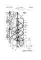
In the accompanying drawing Fig. 1 is a view showing the wall of a building withthe tubular spiral escape secured thereto, the entrances to the tube being in section withparts broken away, selective positions of e'xitinemhere being shown in dotted lines, selective ex panded lower tubular sections being likewise represented.
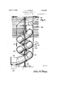
Fig. 2 is a front view of a single entrance spiral tubular escape.
Fig. 3 is a top plan view of thefire escape,
shown in section.
Fig. 4 is an enlargedbroken away detail partly in section, showing parts of two segmental tubular sections, a band or hoop thereon, and bolt mounted in thehoop for the support of twoopposed turn-buckles, the latl ter being broken away.
Fig. 5 is a view showing parts of two tubular segmental sections, a band or hoop encircling them and compressed thereon and showing a pair of opposed turn -buckles mounted in the hoop or band, this view showing the same parts as those illustrated in Fig. 4.
Fig. 6 is a detail showing rings slidingly mounted on the pole for supporting the tube.
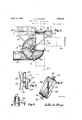
Figs. 7 and 8 illustrate the connection of an upper spiral tube of lesser diameter with a lower tube of greater diameter. Fig. 7 is a plan view showing a lower entranceway and a spi'raltube leading therefrom and in communication with an upper spiral tube oflesser diameter, the latter being in section.- Fig. 8 is a side view of the same.
Referring now to the drawing for aniore particular description, the invention is shown and described in connection with the upright wall 10, together with the floors 11 and 12 and rooms 13 of a building.
In order that the objects first mentioned may be facilitated, I provide a pole or post 14;, preferably of tubular construction adapted to be disposed vertically and having a length sufiicient to extend from the ground to the uppermost room. In order that the pole be suitably supported, it is secured to 15 preferably constructed. of eoncrete adapted to extend into the ground beyond the frost line, a flange 16 being provided for the bottom of the pole so that, by means of bolts, which traverse the flange and are embedded in the concrete, the pole will be firmly grounded, the advantage being that when ,the ground becomes frozen, the pole and its connecting parts will not be appreciably elevated and injury from expansion or contraction avoided.
The upper end of the pole is firmly secured to the building by any suitable means, the means herein shown being a brace 17 of V- shape, its arms being secured to the building by bolts as best shown in Fig. 3 of the drawing and its apex being secured to the pole.
-Numeral 18 indicates a pair of horizontal cross-braces which are secured to the pole below its upper end. Numerals 19 indicate a pair of inclined braces approximately of inverted V-shape, each being secured at its outer end to the ends of a horizontal brace with its apex secured to the pole, and as described, it will be understood that the mount ing of the pole will prevent undue vibration thereof and that the braces 18 and 19 will, in part, operate as a support for the spiral tube to be described.
Each hoop or band 21 preferably consists of two semi-circular parts provided at its ends with lugs 22, and by means of bolts 23 which traverse the lugs. The lugs may be moved toward each other for pressing the end-portions of the sections, at each joint, against each other, one of the objects in view being to avoid the use of rivets, and to permit the parts to be conveniently assembled at the time the device is erected.
While the turn-buckles may be secured to the hoops or hands 21 by any suitable means, I prefer the use of bolts 25 as best shown in Fig. 4 of the drawing, the heads of these bolts being countersunk in the hoops, and the bolts 25 providing a mounting for theterminal eyes'26 of the turn-buckles. It will be seen that by rotating the nuts 27 each being threaded on an end of these bolts, the eyes 26 may be pressed firmly against the hoops.
One of the functions to be discharged by the turn-buckles is to assist in supporting the weight of the sections when the device has been assembled. The important function, however, for the use of the turn-buckles, is that they provide for certain adjustments which must be made in the inclination of the spiral tube, now to be described.
In order that the fire escape mentioned may be practically built, it is obvious that the several sections 20 should be prepared at the factory. These spiral. fire escapes are very useful upon school buildings having three or more floors, each having an entrance thereto, and since the floors of a building may not be uniformly spaced apart, and since the particular sections of the tube which communicate with the entrances from the rooms must be prepared at the factory, it is obvious that the inclination of some of the sections must be changed so that each ena trance may be suitably connected with its tubular section. For instance, if the spiral tube has a uniform inclination throughout its entire length, and it is found that the distance from an upper floor to the floor next m below is a few inches greater than was expected, it is obvious that the sections may be adjusted and may provide a greater inclination for those sections. lVhile this inclination will not interfere in the operation of I two floors of the building is less than was expected, the tubular sections may be ad justed by means of the turn-buckles so that they will have a lesser inclination, and these slight changes in inclination will not interfere with the operation of the device.
This exit member may have any desired with a section of a coil adjacent to and above said lower coil.
5. In a fire escape for a building, a pole adapted to be disposed at the side with its upper end secured to the building, a spiral tube surrounding the pole consisting of interfitting connected sections, hoops encircling the sections, a plurality of vertically positioned longitudinally adjustable links connecting the'hoops of the lower sections of the coils with the hoops of the upper adjacent coils of said tube, a tubular exit member connected with the lowermost section, and an entrance section leading from the building communicating with the uppermost section of said tube. V
6. In a fire escape for a building, a pole adapted to be mounted at the side of the building, cross-braces mounted on the pole, a tube coiled spirally around the pole and secured to the cross-braces and consisting of sections,
the upper end-portion of each lower section overlapping a lower end-portion of an upper section adjacent thereto, a plurality of hoops encircling the overlapping sections and arranged to compress the overlapping end-portions of said sections, vertically disposed longitudinally adjustable links connecting each hoop of a lower section of a coil with the hoop of a section of an adjacent upper coil, an exit-member communicating with said tube, and an entrance-member leading from the building in communication with said tube.
7 In a tubular fire escape for a building, an upper entranceway leading from the building, a lower entranceway leading from said building, an upright spiral tube communicating with the upper entranceway and a second spiral tube of greater diameter than the first named tube extending upwardly from the ground in communication with the lower entranceway and forming a Y-tube connection with said first named tube.
8. In a fire escape for a building, an upper, downwardly inclined entranceway for a communication with the building, a lower downwardly inclined entranceway for a communication with the building, a spiral tube communicating with the upper entranceway, a second spiral tube having a greater diameter than the first named tube and communieating with the lower entranceway and with said first named tube, said tubes near their junction being inclined toward each other at an acute angle. 7
9. In a fire escape for a building, a downwardly inclined chute formed of interfitting sectional members, an entrance-member including a door-jamb and a casing having an inclined bottom leading from a room of the building to said chute, a door mounted on the door jamb to permit it to swing inwardly of the casing, the inclined bottom of the casing.
extending inwardly of the building to open upon the floor inwardly of said door, and a swing bar carried by said jamb above said door.
10. In a fire escape for a building, an upper entranceway leading from the building, a lower entranceway leading from said building, an upright spiral tube communicating with the upper entranceway and a second spiral tube extending upwardly from the ground in communication with the lower entranceway and forming a Y-tube connection with said first named tube.
11. In a fire escape for a building having openings, a sectional spiral tube accessible from said openings, and means for the vertical adjustment of the sections with regard to said openings.
12. In a fire escape for a building, a spiral tube formed of sections, and means connected to said sections for changing the degree of inclination of the sections.
13. In a fire escape for a building, a spiral tube formed of curved sections throughout its entire length and adapted to be disposed in a vertical plane, a door jamb in the wall of said building, a straight member having its bottom inclined and lying above said jamb and having connection with the upper end of the spiral tube, and an exit member having a substantially horizontal portion and connected with the lower end of the spiral tube.
14. In a tubular fire escape for a building, an upper inclined entrance way leading from the building, a lower inclined entrance way leading from said building, an upright spiral tube communicating with the upper entrance way, and a second spiral tube extending upwardly from the ground in communication with the lower entrance way and forming a Y-tube connection with said first named tube.
15. In a fire escape for a building, a spiral tube formed of curved sections throughout its entire length and adapted to be disposed in a vertical plane, a door j amb in the wall of said building, a straight member having its bottom inclined and lying above said jamb and having connection with the upper end of the spiral tube, and an exit member connected with the tube and provided with a flaring month.
In testimony whereof, I have aflixed my signature.
ARTHUR H. STURGES.
Priority Applications (1)
| Application Number | Priority Date | Filing Date | Title |
|---|---|---|---|
| US239415A US1754375A (en) | 1927-12-12 | 1927-12-12 | Fire escape of sliding type |
Applications Claiming Priority (1)
| Application Number | Priority Date | Filing Date | Title |
|---|---|---|---|
| US239415A US1754375A (en) | 1927-12-12 | 1927-12-12 | Fire escape of sliding type |
Publications (1)
| Publication Number | Publication Date |
|---|---|
| US1754375A true US1754375A (en) | 1930-04-15 |
Family
ID=22902029
Family Applications (1)
| Application Number | Title | Priority Date | Filing Date |
|---|---|---|---|
| US239415A Expired - Lifetime US1754375A (en) | 1927-12-12 | 1927-12-12 | Fire escape of sliding type |
Country Status (1)
| Country | Link |
|---|---|
| US (1) | US1754375A (en) |
Cited By (25)
| Publication number | Priority date | Publication date | Assignee | Title |
|---|---|---|---|---|
| US3879026A (en) * | 1973-01-22 | 1975-04-22 | Jr James B Lappin | Universal work holders for assembling curved laminated units |
| US3976176A (en) * | 1975-05-22 | 1976-08-24 | Kurtz John C | Spiral chute device |
| US4167224A (en) * | 1976-10-22 | 1979-09-11 | Mitsubishi Denki Kabushiki Kaisha | Escape chute |
| US4192499A (en) * | 1978-01-17 | 1980-03-11 | Groves Kenneth L Jr | Looped slide |
| US4379551A (en) * | 1980-09-02 | 1983-04-12 | Miracle Recreation Equipment Company | Playground tube slide |
| USD269107S (en) | 1981-05-22 | 1983-05-24 | Brown Robert H | Amusement waterslide |
| USD269105S (en) | 1981-05-22 | 1983-05-24 | Brown Robert H | Amusement waterslide |
| USD269104S (en) | 1981-04-20 | 1983-05-24 | Brown Robert H | Amusement waterslide |
| USD269106S (en) | 1981-05-22 | 1983-05-24 | Brown Robert H | Amusement waterslide |
| US4790531A (en) * | 1985-11-19 | 1988-12-13 | Kajima Corporation | Indoor ski slope and apparatus for making snow thereon |
| US20030116381A1 (en) * | 2000-01-10 | 2003-06-26 | Gomes Junior Jason De Carvalho | Helical ramp life-preserver |
| US20050082116A1 (en) * | 2002-02-04 | 2005-04-21 | Eliyahu Nir | Rescue system for high-rise buildings |
| US20050121257A1 (en) * | 2003-12-08 | 2005-06-09 | Gilles Desrosiers | Survival tower |
| US20050161286A1 (en) * | 2001-10-15 | 2005-07-28 | Eliyahu Nir | Rescue system for high-rise buildings |
| US20080142297A1 (en) * | 2003-12-08 | 2008-06-19 | Gilles Desrosiers | Survival tower |
| USD573222S1 (en) | 2007-02-26 | 2008-07-15 | Playstar, Inc. | Slide |
| US20080207344A1 (en) * | 2007-02-26 | 2008-08-28 | Playstar, Inc. | Tube slide |
| US20090143154A1 (en) * | 2007-11-30 | 2009-06-04 | Frederick Rieber | Enclosed slide |
| USD619186S1 (en) * | 2009-05-19 | 2010-07-06 | Splashtacular, Inc. | Racetrack amusement ride |
| USD629861S1 (en) * | 2008-10-08 | 2010-12-28 | David John Cuttell | Slide |
| US20110021278A1 (en) * | 2007-11-30 | 2011-01-27 | Frederick Rieber | Enclosed slide |
| USD779134S1 (en) * | 2014-10-13 | 2017-02-14 | Steven Robert Summerford | Emergency escape slide |
| USD1027091S1 (en) * | 2022-10-27 | 2024-05-14 | Slick Slide LLC | Recreational slide |
| USD1030935S1 (en) * | 2022-11-01 | 2024-06-11 | Slick Slide LLC | Recreational slide |
| EP4385596A1 (en) * | 2022-12-15 | 2024-06-19 | Yardistry US, LLC | Tube slide having a telescoping base |
-
1927
- 1927-12-12 US US239415A patent/US1754375A/en not_active Expired - Lifetime
Cited By (29)
| Publication number | Priority date | Publication date | Assignee | Title |
|---|---|---|---|---|
| US3879026A (en) * | 1973-01-22 | 1975-04-22 | Jr James B Lappin | Universal work holders for assembling curved laminated units |
| US3976176A (en) * | 1975-05-22 | 1976-08-24 | Kurtz John C | Spiral chute device |
| US4167224A (en) * | 1976-10-22 | 1979-09-11 | Mitsubishi Denki Kabushiki Kaisha | Escape chute |
| US4192499A (en) * | 1978-01-17 | 1980-03-11 | Groves Kenneth L Jr | Looped slide |
| US4379551A (en) * | 1980-09-02 | 1983-04-12 | Miracle Recreation Equipment Company | Playground tube slide |
| USD269104S (en) | 1981-04-20 | 1983-05-24 | Brown Robert H | Amusement waterslide |
| USD269107S (en) | 1981-05-22 | 1983-05-24 | Brown Robert H | Amusement waterslide |
| USD269105S (en) | 1981-05-22 | 1983-05-24 | Brown Robert H | Amusement waterslide |
| USD269106S (en) | 1981-05-22 | 1983-05-24 | Brown Robert H | Amusement waterslide |
| US4790531A (en) * | 1985-11-19 | 1988-12-13 | Kajima Corporation | Indoor ski slope and apparatus for making snow thereon |
| US7048092B2 (en) * | 2000-01-10 | 2006-05-23 | Jason De Carvalho Gomes Junior | Helical ramp life-preserver |
| US20030116381A1 (en) * | 2000-01-10 | 2003-06-26 | Gomes Junior Jason De Carvalho | Helical ramp life-preserver |
| US20050161286A1 (en) * | 2001-10-15 | 2005-07-28 | Eliyahu Nir | Rescue system for high-rise buildings |
| US20050082116A1 (en) * | 2002-02-04 | 2005-04-21 | Eliyahu Nir | Rescue system for high-rise buildings |
| US20050121257A1 (en) * | 2003-12-08 | 2005-06-09 | Gilles Desrosiers | Survival tower |
| US20080142297A1 (en) * | 2003-12-08 | 2008-06-19 | Gilles Desrosiers | Survival tower |
| USD573222S1 (en) | 2007-02-26 | 2008-07-15 | Playstar, Inc. | Slide |
| US20080207344A1 (en) * | 2007-02-26 | 2008-08-28 | Playstar, Inc. | Tube slide |
| USD580507S1 (en) | 2007-02-26 | 2008-11-11 | Playstar, Inc. | Slide entryway |
| US20090143154A1 (en) * | 2007-11-30 | 2009-06-04 | Frederick Rieber | Enclosed slide |
| US7815513B2 (en) | 2007-11-30 | 2010-10-19 | Frederick Rieber | Enclosed slide |
| US20110021278A1 (en) * | 2007-11-30 | 2011-01-27 | Frederick Rieber | Enclosed slide |
| US8382602B2 (en) | 2007-11-30 | 2013-02-26 | Frederick Rieber | Enclosed slide |
| USD629861S1 (en) * | 2008-10-08 | 2010-12-28 | David John Cuttell | Slide |
| USD619186S1 (en) * | 2009-05-19 | 2010-07-06 | Splashtacular, Inc. | Racetrack amusement ride |
| USD779134S1 (en) * | 2014-10-13 | 2017-02-14 | Steven Robert Summerford | Emergency escape slide |
| USD1027091S1 (en) * | 2022-10-27 | 2024-05-14 | Slick Slide LLC | Recreational slide |
| USD1030935S1 (en) * | 2022-11-01 | 2024-06-11 | Slick Slide LLC | Recreational slide |
| EP4385596A1 (en) * | 2022-12-15 | 2024-06-19 | Yardistry US, LLC | Tube slide having a telescoping base |
Similar Documents
| Publication | Publication Date | Title |
|---|---|---|
| US1754375A (en) | Fire escape of sliding type | |
| US4074791A (en) | Emergency fire net | |
| US2936504A (en) | Process for making a concrete shelter | |
| US3196813A (en) | Bomb shelter | |
| US1520440A (en) | Automatic fire escape | |
| US2206680A (en) | Heat insulation curtain | |
| US2518855A (en) | Cattle guard gate | |
| US400470A (en) | Spiral stairway | |
| US1319267A (en) | Vehtilatiitg apparatus | |
| US466831A (en) | Means for protecting buildings from fire | |
| US1134635A (en) | Folding window-balcony. | |
| US1839363A (en) | Helical fire escape | |
| US3251370A (en) | Tent structure | |
| US1018698A (en) | Fire-net. | |
| US4133398A (en) | Collapsible spider for use in supporting casing during upward drilling operations | |
| US1101182A (en) | Silo-building apparatus. | |
| US935447A (en) | Fire-escape. | |
| US2105095A (en) | Portable partition | |
| US502070A (en) | fairchild | |
| US2317459A (en) | Folding fire-escape ladder | |
| US974381A (en) | Fire-escape. | |
| US962295A (en) | False work for building construction. | |
| US1116189A (en) | Fire-escape. | |
| US1155017A (en) | Bird-trap. | |
| US3399438A (en) | Guiding means for sliding shuttering for building structures with slightly inclined and vertical concrete walls |