US1753688A - Tire mender - Google Patents
Tire mender Download PDFInfo
- Publication number
- US1753688A US1753688A US297051A US29705128A US1753688A US 1753688 A US1753688 A US 1753688A US 297051 A US297051 A US 297051A US 29705128 A US29705128 A US 29705128A US 1753688 A US1753688 A US 1753688A
- Authority
- US
- United States
- Prior art keywords
- plate
- tire
- mender
- teeth
- cover plate
- Prior art date
- Legal status (The legal status is an assumption and is not a legal conclusion. Google has not performed a legal analysis and makes no representation as to the accuracy of the status listed.)
- Expired - Lifetime
Links
- 239000007779 soft material Substances 0.000 description 2
- 240000008042 Zea mays Species 0.000 description 1
- 235000005824 Zea mays ssp. parviglumis Nutrition 0.000 description 1
- 235000002017 Zea mays subsp mays Nutrition 0.000 description 1
- 238000005299 abrasion Methods 0.000 description 1
- 239000011248 coating agent Substances 0.000 description 1
- 238000000576 coating method Methods 0.000 description 1
- 235000005822 corn Nutrition 0.000 description 1
- 239000000428 dust Substances 0.000 description 1
- 239000002184 metal Substances 0.000 description 1
- 238000000034 method Methods 0.000 description 1
- 230000008092 positive effect Effects 0.000 description 1
Images
Classifications
-
- B—PERFORMING OPERATIONS; TRANSPORTING
- B29—WORKING OF PLASTICS; WORKING OF SUBSTANCES IN A PLASTIC STATE IN GENERAL
- B29C—SHAPING OR JOINING OF PLASTICS; SHAPING OF MATERIAL IN A PLASTIC STATE, NOT OTHERWISE PROVIDED FOR; AFTER-TREATMENT OF THE SHAPED PRODUCTS, e.g. REPAIRING
- B29C73/00—Repairing of articles made from plastics or substances in a plastic state, e.g. of articles shaped or produced by using techniques covered by this subclass or subclass B29D
- B29C73/04—Repairing of articles made from plastics or substances in a plastic state, e.g. of articles shaped or produced by using techniques covered by this subclass or subclass B29D using preformed elements
- B29C73/14—Repairing of articles made from plastics or substances in a plastic state, e.g. of articles shaped or produced by using techniques covered by this subclass or subclass B29D using preformed elements using elements composed of two parts joined together after having been placed one on each side of the article
-
- B—PERFORMING OPERATIONS; TRANSPORTING
- B29—WORKING OF PLASTICS; WORKING OF SUBSTANCES IN A PLASTIC STATE IN GENERAL
- B29K—INDEXING SCHEME ASSOCIATED WITH SUBCLASSES B29B, B29C OR B29D, RELATING TO MOULDING MATERIALS OR TO MATERIALS FOR MOULDS, REINFORCEMENTS, FILLERS OR PREFORMED PARTS, e.g. INSERTS
- B29K2021/00—Use of unspecified rubbers as moulding material
-
- Y—GENERAL TAGGING OF NEW TECHNOLOGICAL DEVELOPMENTS; GENERAL TAGGING OF CROSS-SECTIONAL TECHNOLOGIES SPANNING OVER SEVERAL SECTIONS OF THE IPC; TECHNICAL SUBJECTS COVERED BY FORMER USPC CROSS-REFERENCE ART COLLECTIONS [XRACs] AND DIGESTS
- Y10—TECHNICAL SUBJECTS COVERED BY FORMER USPC
- Y10T—TECHNICAL SUBJECTS COVERED BY FORMER US CLASSIFICATION
- Y10T152/00—Resilient tires and wheels
- Y10T152/10—Tires, resilient
- Y10T152/10882—Patches
- Y10T152/10891—Mechanically secured
- Y10T152/109—Inside and outside, bolt connected
Definitions
- This invention relates to a tire mender or improved blow out patch.
- the principal object is to provide a mechanical device whereby the side walls of a 5 tire may be held in relatively closed position when pressure is exerted against the side walls upon the inflation of the inner tube.
- Another object is to provide a tire mender with an outside cover plate that will serve l0 to keep the dust and dirt out of the device.
- the cover plate serves to force the teeth on a lower plate into the tire and prevent the spreading of the teeth when pressure is exerted from within.
- the cover l5 plate also servesto limit the depth to which the teeth may be forced in the tire.
- the blow out patch may serve as a means for preventing the inner tube from extending through the cut or blow out, and at the same time, serve to protect the surface of the inner tube.
- Figure l is a section'of a tire showing the 35 the tire mender in position
- Figure 2 is a perspective of the various parts constituting the tire mender showing the various parts separated;
- Figure 3 is a section taken through a tire ailid tire mender showing the tire mender in a ace;
- Y l Figure 4 is a top plan with a'portion of the cover plate broken away;
- Figure 5 is a section taken along line 5 5 of Figure 3.
- Figure 6 is a section similar to Figure 5 showing the tire mender before it has been forced into the tire as shown in Figure 5.
- jacent ythe base plate l is a section of the usual tire 5 showing a rupture.
- The'screlw members 3 passi. through the tire 5 and fsecure a plate 7 in alinement with ybase plate l and on the outside of the tire 5.
- a plate 7 Alongthe edge of plate7 are teeth 8, at an angle-to the plate 7.
- a cover plate 9 On top of ⁇ the plate 7 is a cover plate 9 having flangesl() which extend around the plate 7 on all sides'.
- Nuts 11 orother suitable securing means bear against'gthe cover plate 91andraiford means forjdrawingthe base plate lsecurely against the tire s 15'which in turn is fo-ced vagainst they plate 7 and teeth 8.
- the base plate l is 4smaller than the ,plate'7 and may be forced up within the teethy 8 so'as to bear,v against vthe tire and indirectly against thef plate v7.
- This ' is highly desirable as it permits a much closer contact, and atthe same time forces theteeth y8 securelyinto the tire 5F g'
- a. base plate -l' will be placed ⁇ on' the insideo'f the-tire op- Y posite the rupture. The screws will thenbe forced in the tireprefera'bly at points where there isa rupture or abrasion.
- rlhe plate 7 is then placed upon'V the screws with a cover plate 9'on ⁇ top of the plate 7.
- ltj willbe noted,.as shown -inl Figure 6 that the 'teeth 8 proj ectat anacute angle from the plate 7 and that the cover plate 9 does not fit over the plate 7, but merely rests against the same.
- the cover plate 9 Upon pressure being exerted due to the tightening of the nut 11, the cover plate 9 will be forced over the plate 7, and due to the flanges l0 extending around the plate 9, the teeth 8 will be forced inwardly at the same time drawing the side walls adjacent the rupture closer ly over the platev 7,.the teeth 8 will be firmly together until when the cover plate 9 fits snugf imbedded in the tire and at approximately a f right angle to the plate 7.
- the cover plate 9 serves to limit the movement of the teeth 8 inwardly and as soon as the flange l0 cornes in contact with the casing, it will serve as a stop.
- the cover plate 9 further serves to prevent the spreading of the teeth 8 when the tire is filled with air.
- flange l() affords a very convenient method of 'removing the plate 7 as the two will be locked together and ascrew driver or similar tool may be inserted under the flange l0 and thus very easily remove the plate 7 from the tire. It willbe noted that upon the teeth 8 being forced inwardly by the flange 10, a shoulder will be formed securely holding the flange 10 in place, and locking the plates 9 and'7 together.
- the base plate l will be forced upwardly, and since it is smaller than either of the other plates, it will'have a tendency to seat within the plate 7. This action will result in a flush surface on the inside of the tire and overcomes one of the very common troubles, where a boot or patch is used, namely, of such article forming an obstruction within the tire which may pinch or wear against the tube causing a deflation of the tire.
- the metal plate 1 is protected with a coating of rubber orother soft material.
- a tire mender comprising a base plate, a second plate secured to said base plate, said second plate having teeth angularly disposed to said plate, a cover plate adjacentsaid second plate, said cover plate having a flangeeX- tending around its edges and overlapping said second plate, securing means passing through all the mentionedplates, for drawing the teeth on said second plate within the flange on said cover plate.
- a tire mender comprising a base plate, a second plate, said second plate having teeth angularly disposed to said second plate, a cover plate adjacent said second plate, said -cover plate having allangel extending around its edges and overlapping said second plate, means forsecuring said plates together and for drawing the teeth on said second plate within the flange on said cover plate.
Landscapes
- Engineering & Computer Science (AREA)
- Mechanical Engineering (AREA)
- Tires In General (AREA)
Description
April-8, 1930. J. M* BOSCARDIN TIRE MENDER Filed Aug. 2,l 1928 Patented Apr. 8, 1930 UNITED STATES JOHN M. BoscAaDIN, or carreau; oouuncrrcufrff l TIRE MENDER y .v iv
`Application filed August 2, 1928. Serial-No. 297,051.
This invention relates to a tire mender or improved blow out patch.
The principal object is to provide a mechanical device whereby the side walls of a 5 tire may be held in relatively closed position when pressure is exerted against the side walls upon the inflation of the inner tube.
Another object is to provide a tire mender with an outside cover plate that will serve l0 to keep the dust and dirt out of the device. At the same time, the cover plate serves to force the teeth on a lower plate into the tire and prevent the spreading of the teeth when pressure is exerted from within. The cover l5 plate also servesto limit the depth to which the teeth may be forced in the tire.
Other objects will be shown in the, specilication and drawings.
At the present time where a blow out patch 29 is used, there is no attempt made to prevent the walls of the tire adjacent the blow out or cut from expanding under pressure.
The blow out patch may serve as a means for preventing the inner tube from extending through the cut or blow out, and at the same time, serve to protect the surface of the inner tube. By the use of the device described herein, the side walls adjacent the rupture or cut are prevented from stretching, thus saving the general tire structure, and at the same time, more direct and positive action is obtained.
In the drawings:
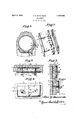
Figure l is a section'of a tire showing the 35 the tire mender in position;
Figure 2 is a perspective of the various parts constituting the tire mender showing the various parts separated;
Figure 3 is a section taken through a tire ailid tire mender showing the tire mender in a ace; Y l Figure 4 is a top plan with a'portion of the cover plate broken away;
Figure 5 is a section taken along line 5 5 of Figure 3; and
Figure 6 is a section similar to Figure 5 showing the tire mender before it has been forced into the tire as shown in Figure 5.
Referring to the drawings in which similar numerals designate like parts:
jacent ythe base plate l is a section of the usual tire 5 showing a rupture. i The'screlw members 3 passi. through the tire 5 and fsecure a plate 7 in alinement with ybase plate l and on the outside of the tire 5. Alongthe edge of plate7 are teeth 8, at an angle-to the plate 7. On top of `the plate 7 is a cover plate 9 having flangesl() which extend around the plate 7 on all sides'. Nuts 11 orother suitable securing means, bear against'gthe cover plate 91andraiford means forjdrawingthe base plate lsecurely against the tire s 15'which in turn is fo-ced vagainst they plate 7 and teeth 8. Y i A yIt willbe noted that the base plate l is 4smaller than the ,plate'7 and may be forced up within the teethy 8 so'as to bear,v against vthe tire and indirectly against thef plate v7. This 'is highly desirable as it permits a much closer contact, and atthe same time forces theteeth y8 securelyinto the tire 5F g' As actually 'used upona tire having a blow out or a rupture in the side walls", a. base plate -l' will be placed `on' the insideo'f the-tire op- Y posite the rupture. The screws will thenbe forced in the tireprefera'bly at points where there isa rupture or abrasion. rlhe plate 7 is then placed upon'V the screws with a cover plate 9'on`top of the plate 7. ltjwillbe noted,.as shown -inlFigure 6 that the 'teeth 8 proj ectat anacute angle from the plate 7 and that the cover plate 9 does not fit over the plate 7, but merely rests against the same. Upon pressure being exerted due to the tightening of the nut 11, the cover plate 9 will be forced over the plate 7, and due to the flanges l0 extending around the plate 9, the teeth 8 will be forced inwardly at the same time drawing the side walls adjacent the rupture closer ly over the platev 7,.the teeth 8 will be firmly together until when the cover plate 9 fits snugf imbedded in the tire and at approximately a f right angle to the plate 7.
The cover plate 9 serves to limit the movement of the teeth 8 inwardly and as soon as the flange l0 cornes in contact with the casing, it will serve as a stop. The cover plate 9 further serves to prevent the spreading of the teeth 8 when the tire is filled with air. Again, flange l() affords a very convenient method of 'removing the plate 7 as the two will be locked together and ascrew driver or similar tool may be inserted under the flange l0 and thus very easily remove the plate 7 from the tire. It willbe noted that upon the teeth 8 being forced inwardly by the flange 10, a shoulder will be formed securely holding the flange 10 in place, and locking the plates 9 and'7 together.
As soon as the plate 7 has been forced rinto position by the plate 9, the base plate l will be forced upwardly, and since it is smaller than either of the other plates, it will'have a tendency to seat within the plate 7. This action will result in a flush surface on the inside of the tire and overcomes one of the very common troubles, where a boot or patch is used, namely, of such article forming an obstruction within the tire which may pinch or wear against the tube causing a deflation of the tire. To further guard against any lsuch contingency, the metal plate 1 is protected with a coating of rubber orother soft material.
Having thus described my invention, what I claim is:
1. A tire mender comprising a base plate, a second plate secured to said base plate, said second plate having teeth angularly disposed to said plate, a cover plate adjacentsaid second plate, said cover plate having a flangeeX- tending around its edges and overlapping said second plate, securing means passing through all the mentionedplates, for drawing the teeth on said second plate within the flange on said cover plate.
2. A tire mender comprising a base plate, a second plate, said second plate having teeth angularly disposed to said second plate, a cover plate adjacent said second plate, said -cover plate having allangel extending around its edges and overlapping said second plate, means forsecuring said plates together and for drawing the teeth on said second plate within the flange on said cover plate.
,In testimony whereofI afiiX my signature.
JOI-IN VBDSVCARDIN.
Priority Applications (1)
| Application Number | Priority Date | Filing Date | Title |
|---|---|---|---|
| US297051A US1753688A (en) | 1928-08-02 | 1928-08-02 | Tire mender |
Applications Claiming Priority (1)
| Application Number | Priority Date | Filing Date | Title |
|---|---|---|---|
| US297051A US1753688A (en) | 1928-08-02 | 1928-08-02 | Tire mender |
Publications (1)
| Publication Number | Publication Date |
|---|---|
| US1753688A true US1753688A (en) | 1930-04-08 |
Family
ID=23144642
Family Applications (1)
| Application Number | Title | Priority Date | Filing Date |
|---|---|---|---|
| US297051A Expired - Lifetime US1753688A (en) | 1928-08-02 | 1928-08-02 | Tire mender |
Country Status (1)
| Country | Link |
|---|---|
| US (1) | US1753688A (en) |
Cited By (3)
| Publication number | Priority date | Publication date | Assignee | Title |
|---|---|---|---|---|
| US3261393A (en) * | 1963-05-17 | 1966-07-19 | Templeton Kenly & Company | Apparatus and method for patching screens |
| US20130213556A1 (en) * | 2010-10-29 | 2013-08-22 | Compagnie Generale Des Etablissements Michelin | Flexible guide for tire repair |
| US9266293B2 (en) | 2010-10-30 | 2016-02-23 | Michelin Recherche Et Technique S.A. | Depth marking tool for tire repair |
-
1928
- 1928-08-02 US US297051A patent/US1753688A/en not_active Expired - Lifetime
Cited By (4)
| Publication number | Priority date | Publication date | Assignee | Title |
|---|---|---|---|---|
| US3261393A (en) * | 1963-05-17 | 1966-07-19 | Templeton Kenly & Company | Apparatus and method for patching screens |
| US20130213556A1 (en) * | 2010-10-29 | 2013-08-22 | Compagnie Generale Des Etablissements Michelin | Flexible guide for tire repair |
| US9561628B2 (en) * | 2010-10-29 | 2017-02-07 | Michelin Recherche Et Technique S.A. | Flexible guide for tire repair |
| US9266293B2 (en) | 2010-10-30 | 2016-02-23 | Michelin Recherche Et Technique S.A. | Depth marking tool for tire repair |
Similar Documents
| Publication | Publication Date | Title |
|---|---|---|
| US1753688A (en) | Tire mender | |
| EP0036908A1 (en) | Safety ring for pneumatic vehicle tyres | |
| US2620852A (en) | Tire repair method | |
| US2313689A (en) | Rubber press pad | |
| US1245362A (en) | Lock-nut. | |
| US645502A (en) | Repair-plug for pneumatic tires. | |
| US267862A (en) | fletcher | |
| US1097218A (en) | Lock-nut. | |
| US2523044A (en) | Glass window hurricane protector | |
| US1498683A (en) | Tire-repair means | |
| US2889579A (en) | Vulcanizer | |
| US934639A (en) | Tire. | |
| US3357592A (en) | Closure | |
| US1207294A (en) | Method of repairing tires. | |
| US1269124A (en) | Blow-out patch. | |
| US955309A (en) | Bottle. | |
| US1049090A (en) | Device for repairing pneumatic-tire tubes. | |
| US1279301A (en) | Means for repairing tire-casings. | |
| US1331391A (en) | Antiskid device | |
| US748256A (en) | Elastic tire for vehicles. | |
| US1532603A (en) | Lock nut | |
| US1215582A (en) | Tire-plug. | |
| US1586104A (en) | Blow-out patch | |
| US644548A (en) | Nut-lock. | |
| US1358962A (en) | Pneumatic tire |