US1753686A - Basement circulator - Google Patents
Basement circulator Download PDFInfo
- Publication number
- US1753686A US1753686A US222169A US22216927A US1753686A US 1753686 A US1753686 A US 1753686A US 222169 A US222169 A US 222169A US 22216927 A US22216927 A US 22216927A US 1753686 A US1753686 A US 1753686A
- Authority
- US
- United States
- Prior art keywords
- water
- casing
- basement
- circulator
- nozzle
- Prior art date
- Legal status (The legal status is an assumption and is not a legal conclusion. Google has not performed a legal analysis and makes no representation as to the accuracy of the status listed.)
- Expired - Lifetime
Links
- XLYOFNOQVPJJNP-UHFFFAOYSA-N water Substances O XLYOFNOQVPJJNP-UHFFFAOYSA-N 0.000 description 27
- 239000007921 spray Substances 0.000 description 5
- 238000010276 construction Methods 0.000 description 3
- 150000001768 cations Chemical class 0.000 description 1
- 239000007789 gas Substances 0.000 description 1
- 231100000614 poison Toxicity 0.000 description 1
- 230000007096 poisonous effect Effects 0.000 description 1
- 238000007493 shaping process Methods 0.000 description 1
Images

Classifications
-
- A—HUMAN NECESSITIES
- A62—LIFE-SAVING; FIRE-FIGHTING
- A62C—FIRE-FIGHTING
- A62C31/00—Delivery of fire-extinguishing material
- A62C31/005—Delivery of fire-extinguishing material using nozzles
Definitions
- My invention relates to improvements in hose nozzles, and it consists in the combinations, constructions and arrangementshereinafter described and claimed.
- An object of my invention is to provide a hose nozzle which is especially designed to be lowered into the hold of aship for fighting hidden fires or for fighting fires in basements.
- the different parts of the nozzle are so shaped and arranged with respect to each other as to cause a portion of the water flowing from the nozzle to be ejected in an apron-like spray that extends substantially at right angles to the axis of the nozzle and lies in a flat plane; and to cause the other portion of the water to be ejected througha plurality of small openings which are inclined at such an angle as to cause the water to be directed into the space surrounding the hose and nozzle.
- a further object of my invention is to provide a device of the type described which is simple in construction and which is durable and efficient for the purpose intended.
- Figure 2 is a section along the line 22 of Figure 1;
- Figure 3 is a side elevation of a modifie portion of the device.
- Figure 4 is a top plan View of the portion of the device shown in Figure 3.
- FIG. 1 clearly shows how the casing 1 is provided with diametrically disposed projections 4 by means of which the casing may be screwed upon the hose 3.
- the casing has an enlarged compartment 5 and the upper wall of the compartment has openings 6 therein through which aportion of the water enteringthe casing may flow.
- the casing 1 is reduced at 7 and is provided with an external described.
- the special construction of the-element 9 is shown in Figures 1 and 2, and it will be noted that the Water upon entering the element at its center is deflected by a conicalshaped projection 10 into .three channels 11 see Figure 2. These channels have curved side walls 12 and 13 for imparting a whirling motion to the water as it passes therethrough. The channels are curved to such an extent that a radial line 14 passing the inner corner 15 of the channel 11 bisects the outer open end 16. It is this special manner of shaping that causes the water to be whirled at the desired speed as it leaves the element 9.
- Figure 1 further shows how the element 9 has a shoulder 17 projecting beyond the periphery 18 of the portion housing the passageways. 11.
- the outer diameter of the shoulder 17 has threads 18 forreceiving a cup-shaped member 19.
- This member together with the element 9, forms a water passageway 20 that receives the water issuing from the passageways 11 and causes it to flow inthe direction of the arrows shown in Figure 1 until the water finally emerges from anopening 21 in the top of the member 19.
- the exterior surface of the casing 1 at a point adjacent to the opening 21 is curved'as at 22, for causing the waterto be ejected from thenoz zle in a plane substantially at right apgles to the longitudinal axis of the nozz e. 1 V 7 From the foregoing description of the various parts of the device the operation thereofwill be readily understood.
- the nozzle is especially designed for fighting hidden fires such as occur in the holds of a ship. Oftentimes fires which originate in v the holds of a ship cannot be successfully fought, because it is impossible for the firemen to enterthe hold, due to the flames and poisonous gases and a nozzle which will direct a stream of water in a line parallel to the hosewill not always be effective .for fighting such fires, because the fire may be in some remote part of the hold Whereit is impos- Ill) sible to direct the stream of water. With the present device, the nozzle may be lowered through the trap door and be suspended by the hose itself at the desired distance above the floor.
- the element 9 has'sockets 26 therein, for receiving a spanner wrench when it is desired to secure the element to the casing 1.
- a basement circulator comprising a casing and housing having an annular unob structed water outlet opening formed by them, means disposed within said housing for whirling the water, said casing having an outwardly-extending curved portion overlying the water outlet for directing the water outwardly, and a flat horizontal portion extending from the curved portion for projecting the water in an apron-like spray transversely to the axis of the circulator.
- a basement circulator comprising a casing, aho'using enclosing the outlet end of said casing and having an opening disposed concentric with the casing outlet for forming an annular water outlet opening, a member mounted in said housing for whirling the water, said casing having acurved portion flaring outwardly from the annular outlet and merging into a flat horizontal portion for directing water issuing from the annular outlet in an apron-like spray;
- a basement circulator comprising a casing having a water outlet, a housing enclosing the outlet end of said casing and having an opening therein disposed in concentric relation with the casing outlet for forming an annular water outlet opening, and means carried by said housing for directing the water radially from the casing outlet, said casing having a curved ortion flaring outwardly
Landscapes
- Health & Medical Sciences (AREA)
- Public Health (AREA)
- Business, Economics & Management (AREA)
- Emergency Management (AREA)
- Nozzles (AREA)
Description
April 1930- c. A. BORG ESON 1,753,686
BASEMENT CIRCULATOR Filed Sept.=l 26, 1927 '2 Sheets-Sheet l INVENTOR ATTORNEYS.
April 1930. CA. BORGESON 1,753,686
BASEMENT CIRCULATOR Filed Sept. 26, 1927 2 Sheets-Sheet 2 INVENTOR CHA ELEJ .4 Eye $550.
ATTOR N EYS Patented Apr. 8;, 1930 curta n! STATES PATENT ()FFICE CHARLES A. BOBG-ESON, OF SAN FRANCISCO, CALIFORNIA, ASSIGNOR OF TWENTY-FOUR AND ONE-HALF PER CENT TO GEORGE W. MITCHELL AND TWENTY-FOUR AND ONE- HALF PER CENT TO ALVA J. LINDERSMITH, BOTH OF SAN FRANCISCO, CALIFORNIA BASEMENT orncurln'ron.
My invention relates to improvements in hose nozzles, and it consists in the combinations, constructions and arrangementshereinafter described and claimed.
An object of my invention is to provide a hose nozzle which is especially designed to be lowered into the hold of aship for fighting hidden fires or for fighting fires in basements. The different parts of the nozzle are so shaped and arranged with respect to each other as to cause a portion of the water flowing from the nozzle to be ejected in an apron-like spray that extends substantially at right angles to the axis of the nozzle and lies in a flat plane; and to cause the other portion of the water to be ejected througha plurality of small openings which are inclined at such an angle as to cause the water to be directed into the space surrounding the hose and nozzle.
A further object of my invention is to provide a device of the type described which is simple in construction and which is durable and efficient for the purpose intended.
Other objects and advantages will appear in the following specification and thenovel features of my invention will be particularly pointed out in the appended claims.
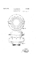
My invention is illustrated in the accompanying drawings forming a part of this appli cation in which Figure 1 is a vertical section through the device;
Figure 2 is a section along the line 22 of Figure 1;
Figure 3 is a side elevation of a modifie portion of the device; and
Figure 4 is a top plan View of the portion of the device shown in Figure 3.
In carrying out my invention I provide a casing 1, having internal threads 2 for receiving the end of a hose 3, see Figure 3. Figure 1 clearly shows how the casing 1 is provided with diametrically disposed projections 4 by means of which the casing may be screwed upon the hose 3. The casing has an enlarged compartment 5 and the upper wall of the compartment has openings 6 therein through which aportion of the water enteringthe casing may flow. The casing 1 is reduced at 7 and is provided with an external described.
The special construction of the-element 9 is shown inFigures 1 and 2, and it will be noted that the Water upon entering the element at its center is deflected by a conicalshaped projection 10 into .three channels 11 see Figure 2. These channels have curved side walls 12 and 13 for imparting a whirling motion to the water as it passes therethrough. The channels are curved to such an extent that a radial line 14 passing the inner corner 15 of the channel 11 bisects the outer open end 16. It is this special manner of shaping that causes the water to be whirled at the desired speed as it leaves the element 9.
Figure 1 further shows how the element 9 has a shoulder 17 projecting beyond the periphery 18 of the portion housing the passageways. 11. The outer diameter of the shoulder 17 has threads 18 forreceiving a cup-shaped member 19. This member, together with the element 9, forms a water passageway 20 that receives the water issuing from the passageways 11 and causes it to flow inthe direction of the arrows shown in Figure 1 until the water finally emerges from anopening 21 in the top of the member 19. The exterior surface of the casing 1 at a point adjacent to the opening 21 is curved'as at 22, for causing the waterto be ejected from thenoz zle in a plane substantially at right apgles to the longitudinal axis of the nozz e. 1 V 7 From the foregoing description of the various parts of the device the operation thereofwill be readily understood.
As stated in the first part ofthe specification, the nozzle is especially designed for fighting hidden fires such as occur in the holds of a ship. Oftentimes fires which originate in v the holds of a ship cannot be successfully fought, because it is impossible for the firemen to enterthe hold, due to the flames and poisonous gases and a nozzle which will direct a stream of water in a line parallel to the hosewill not always be effective .for fighting such fires, because the fire may be in some remote part of the hold Whereit is impos- Ill) sible to direct the stream of water. With the present device, the nozzle may be lowered through the trap door and be suspended by the hose itself at the desired distance above the floor. The water will be thrown from the nozzle in an apron-like spray, which as heretofore stated, will extend substantially at right angles through the axis of the nozzle. This spray has enough force to carry it approximately forty feet or more away from the nozzle. It will therefore be seen that the remote parts of the hold will be quickly drenched by water when the device is used. Vater will also be ejected from theopen-' ings 6, and this water will be sprayed around the points adjacent to the nozzle and hose. In Figure 3 I show a slightly modified form of the device, this form being identical to the form already described with the exception that the curved surface 22 in the former device is made up of a plurality of planes 23, 2% and 25 in the modified form of the device. These planes will deflect the water in substantially the same manner as the curved portion 22. The element 9 has'sockets 26 therein, for receiving a spanner wrench when it is desired to secure the element to the casing 1. Although I have shown and described one embodiment of my invention, it is to be understood that the same is susceptible of various changes and I reserve the right to employ such changes as may come within the sc'op'e'of the appended claims.
I claim: 7 V 1. A basement circulator comprising a casing and housing having an annular unob structed water outlet opening formed by them, means disposed within said housing for whirling the water, said casing having an outwardly-extending curved portion overlying the water outlet for directing the water outwardly, and a flat horizontal portion extending from the curved portion for projecting the water in an apron-like spray transversely to the axis of the circulator.
2. A basement circulator comprising a casing, aho'using enclosing the outlet end of said casing and having an opening disposed concentric with the casing outlet for forming an annular water outlet opening, a member mounted in said housing for whirling the water, said casing having acurved portion flaring outwardly from the annular outlet and merging into a flat horizontal portion for directing water issuing from the annular outlet in an apron-like spray;
8. A basement circulator comprising a casing having a water outlet, a housing enclosing the outlet end of said casing and having an opening therein disposed in concentric relation with the casing outlet for forming an annular water outlet opening, and means carried by said housing for directing the water radially from the casing outlet, said casing having a curved ortion flaring outwardly
Priority Applications (1)
| Application Number | Priority Date | Filing Date | Title |
|---|---|---|---|
| US222169A US1753686A (en) | 1927-09-26 | 1927-09-26 | Basement circulator |
Applications Claiming Priority (1)
| Application Number | Priority Date | Filing Date | Title |
|---|---|---|---|
| US222169A US1753686A (en) | 1927-09-26 | 1927-09-26 | Basement circulator |
Publications (1)
| Publication Number | Publication Date |
|---|---|
| US1753686A true US1753686A (en) | 1930-04-08 |
Family
ID=22831159
Family Applications (1)
| Application Number | Title | Priority Date | Filing Date |
|---|---|---|---|
| US222169A Expired - Lifetime US1753686A (en) | 1927-09-26 | 1927-09-26 | Basement circulator |
Country Status (1)
| Country | Link |
|---|---|
| US (1) | US1753686A (en) |
-
1927
- 1927-09-26 US US222169A patent/US1753686A/en not_active Expired - Lifetime
Similar Documents
| Publication | Publication Date | Title |
|---|---|---|
| US20110272486A1 (en) | Method for spraying a medium and spraying nozzle | |
| US20250065164A1 (en) | Method of Protecting An Occupancy Using A Pendent Fire Protection Sprinkler Arrangement Configured To Be Mounted In A Ceiling And Related Pendent Fire Protection Sprinkler Arrangement | |
| US2647800A (en) | Fire extinguishing nozzle and distributor head | |
| US4291835A (en) | Mist producing nozzle | |
| US1474603A (en) | Liquid and gas mixer | |
| US1753686A (en) | Basement circulator | |
| US2559592A (en) | Vapor or fog nozzle | |
| RU2516641C1 (en) | Fire extinguishing system with deluge sprinkler | |
| CN110025914A (en) | End cap type reagent nozzle | |
| US1395442A (en) | Spray-nozzle | |
| RU2297865C1 (en) | Irrigator | |
| KR20160111804A (en) | water injection device | |
| CA2679002A1 (en) | Ambient mist head | |
| US1037785A (en) | Sprayer for fire-hose and the like. | |
| US1288123A (en) | Cornice sprinkler-head. | |
| US1606377A (en) | Basement circulator | |
| RU2551063C1 (en) | Fluid sprayer | |
| US1439176A (en) | Sprinkler head | |
| RU2622793C1 (en) | Kochetov's pneumatic dispenser | |
| US1605622A (en) | Fireman's water-screen apparatus | |
| US3895759A (en) | Dry chemical dispersion nozzle | |
| US2140517A (en) | Vaporizing nozzle | |
| US993498A (en) | Hose-nozzle and sprinkler. | |
| US1593500A (en) | Sprinkler | |
| US1156474A (en) | Sprinkling or spraying device. |