US1753682A - Truing mechanism - Google Patents
Truing mechanism Download PDFInfo
- Publication number
- US1753682A US1753682A US100442A US10044226A US1753682A US 1753682 A US1753682 A US 1753682A US 100442 A US100442 A US 100442A US 10044226 A US10044226 A US 10044226A US 1753682 A US1753682 A US 1753682A
- Authority
- US
- United States
- Prior art keywords
- truing
- bed
- tool
- screw
- wheel
- Prior art date
- Legal status (The legal status is an assumption and is not a legal conclusion. Google has not performed a legal analysis and makes no representation as to the accuracy of the status listed.)
- Expired - Lifetime
Links
Images
Classifications
-
- B—PERFORMING OPERATIONS; TRANSPORTING
- B24—GRINDING; POLISHING
- B24B—MACHINES, DEVICES, OR PROCESSES FOR GRINDING OR POLISHING; DRESSING OR CONDITIONING OF ABRADING SURFACES; FEEDING OF GRINDING, POLISHING, OR LAPPING AGENTS
- B24B53/00—Devices or means for dressing or conditioning abrasive surfaces
- B24B53/04—Devices or means for dressing or conditioning abrasive surfaces of cylindrical or conical surfaces on abrasive tools or wheels
Definitions
- This'invention relates to improvements in truing mechanism and hasparticular reference to the mechanism for maintaining proper operative surface on the grinding 8 wheel of a centerless grinder.
- Centerless grinders as known to the trade today are employed for precision grinding of articles of circular form in cross-section, with a very high degree of accuracy. That this accuracy may be properly attained, it is essential that the operative surface of the grinding-wheel be kept in proper condition andany inequalities due to irregularwearing of the surface, quickly removed.
- a further object of the present invention is the provision of an improved truing mecha nism which may be either semi-automatic or entirely automatic in operation as preferred.
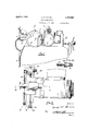
- Figure 1 is a fragmentary view of a centerless grinder embodying the invention.
- Figure2 is an enlarged fragmentary plan view.
- g V is a fragmentary view of a centerless grinder embodying the invention.
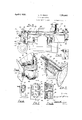
- Figure 3 is an end view of the machine showing the control parts for the truing mechanism.
- Figure 4 is a detail of the drive mechanism for the feed screw and associateparts.
- Figure '5 is a sectional-view through the truing device and its supporting parts taken as on the line 5-5 of Figure 2.
- Figure 6 is a detail view of the switch shifting member.
- FIG. 7 is an enlarged View of the switch members with the control piece removed, as on line 77 of Figure 4.
- FIG. 8 is a sectional View as on the line 8 8 of Figure 7.
- F igure 9 is an enlarged detailed view of a different form of switch controlling device.
- Fig. 10 is a fragmentary sectional view illustrating the clutch for coupling the power mechanism to the screw.
- Centerless grinders of the type here illustrated comprise'a bed or support A, bearing a slide B for the regulating wheel 0 and a suitable housing D for the grinding wheel E, to be operated on by the present automatic truing device.
- the member D is provided with a bracket portion 10'for the supplemental bracket portion 11,- having the annular bearing 12 for the trunnion 13 on the under-side of the tr-uing device'bed 14.
- This bed is provided with the lateral portions 15 riding on the arms 16 of member 11 and having locking bolts 17, depending through said arms. These bolts are shiftable in the slots 18 of the arms 16 by adjustment of the screws 19, whereby the bed 14 may be initially set at any desired angle and secured in this position by tightening of screws 17 and 19. a
- the upper surfaceof the bed 14 is planned to provide the ways 20 on which is slidable the truing table 21, the parts being held in proper relationship one to the other-by engagement of semi-dovetail rib 22 on the bed within the guide slot 23 of the table 21.
- This table is provided with a tubular socket at 24 to receive the sleeve 25 in which is slidably retained the holder 26 for truing diamond 27, a screw threaded adjusting member 28, rotatably held in the end of the sleeve and in threaded engagement with the shank of the tool26, permits in and out adjustment of the tool relativeto its retaining sleeve as desired.
- the sleeve 25 projects inwardly through a transverse slot '30 in the housing D for the grinding wheel protected by a suitable sliding cover plate.
- the truing point may be moved transversely of the wheel surface for truing of same, while escape of the grinding fluid or coolant is prevented by said cover.
- Angular setting of the bed will cause the grinding wheel to be trued off at an angle, while a right angle relationship between truing tool and grinding wheel axis will cause the production of the surface of revolution on the grinding wheel parallel with its axis of rotation.
- the adjusting screw 31 rotatably supported by brackets 32 on the bed but held against longitudinal movement with respect thereto.
- This screw has threaded engagement with the truing tool table, so that upon rotation of the screw in one direction or the other the table will be moved transversely on the bed, carrying with it the truing tool 26.
- the screw is provided with a hand wheel 33, by which this relative movement may be imparted and in addition means for automatically rotating'the screw in either direction as desired are provided.
- These means include a reversible motor 34, secured to one end of the bed 14 and connected by belt 35, with a pulley on shaft 36 which, bears the reduction worm 37, operating worm gear 38 on stub shaft 39.
- a clutch 40 serves to operatively associate stub shaft 39 and screw 31 for power actuation of the latter or to disconnect the parts when manual operation is desired.
- Rising from the bed 14 adjacent the motor 34 is a bracket 41 particularly shown in detail in Figure 8. This bracket bears a pair of insulated plates 42 and 43 having the spaced contacts 44, 45, 46 and 47. Pivoted to plate 42 is a trifurcated switch member 48 and to the lower plate a similar oppositely disposed switch member 49.
- These members are centrally electrically associated and have their two outer terminals adapted for alternate contact with terminals 44, 45 or 46 and 47 respectively of the two switch sections.
- the terminals ust mentioned are the terminals of the motor circuit and control the actuation of the motor.
- the motor will be operated to rotate the screw in a direction to move the truing tool and its table from left to right, as viewed in Figures 3 of the drawing, this being the position the parts are shown as occupying in Figures 3, 6 and 7 for example.
- the switch is reversed to close the circuit through contacts 45 and 46 the motor will reversed, rotating the crew in the opposite direction or from right to left, considering Figure 3 of'the drawing.
- Rod 56 is provided with a plurality of adjusting collars 66, 67,68 and 69.
- Collars 66 and 67' are preferably so adjusted as to loosely fit each side of yoke 55, so that the yoke will. be moved upon longitudinal movementof the rod.
- Collars 68 and 69 on the other hand are so adjusted as to be engaged by abutment70 on the truing tool table 21 when it has made the desired movement or stroke in one'dir'ection or the other, which is to say ordinarily when it has been laterally shifted beyond the edge of the grinding wheel.
- means such as the rack 1 and pinion 72 controlled by the handle 73 may be employed to manually shift the rod 56 the necessary additional amount to reverse the motor for return movement.
- I claim- 1 The combination with a grinder having a. wheel housing, of a bracketcarried by the housing and including a guide member, a table movable on the guide member and hearing a truing tool, the housing having a slot through which the tool extends for engagement with the wheel within the housing, screw mechanism for reciproating the table and tool, means for manually actuating the screw to reciprocate the truing tool, and power means carried by the bracket couplable with the screw for independent actuation thereof.
- Truing mechanism for purpose described, including a support, a truing tool reciprocable on the support, electrically operated means for shifting the tool on the support, a control switch therefor, means movable with the tool for automatic operation of the control switch, and additional means for manually operating said control switch.
- Wheel truing mechanism including a support, a bed mounted on the support for angular adjustment relative thereto, a table transversely movable on the bed, a cross-feed screw for actuating said table, a truing device mounted on the table, means for manually actuating the cross-feed screw, power driving mechanism carried by the bed and coupable with the screw for actuation there of, a clutch'member for operably associating the power mechanism and screw, and means for controlling the direction of power drive of the cross-feed screw, including'a slidable control member, a reversing device operably associated therewith, inter-engageable means on the table and control member for operating the latter on movement of the table, and supplemental manually operable means for shifting said control member, independent of the inter-engaging devices on the member with a rack portion for manual shifting of p the control member.
- a grinding machine the combination with an abrasive wheel, of a self-contained truing mechanism therefor, comprising an angularly adjustable bed, a truing tool movable longitudinally of the bed,-means carried by the bed for efiecting said tranverse movements of the truing tool, said means including a motor mounted on the bed, means for varying the rate of movement transmitted from the motor to the tool, and additional means for manually shifting 'the tool inde pendent of the motor.
Landscapes
- Engineering & Computer Science (AREA)
- Mechanical Engineering (AREA)
- Grinding-Machine Dressing And Accessory Apparatuses (AREA)
Description
April 1930- G. w. BINNS 1,753,682
TRUING MECHANISM Filed April 1,926 2 Sheets-Sheet 2 III 65 Patented Apr. 8, 1930 :uivirrfb STAT-ES PATENT IVOFFICE" GEORGE w. BINNS, or CINCINNATI, OHIO, AssIeNoR, BY vInsNE AssIeNmiN'rs'ro CINCINNATI GRINDER-S INCORPORATED, or CINCINNATI, OHIO, A CORPORATION or OHIO rnUINe MECHANISM v Application filed A rii'i, 1926. Serial No. 100,442..
This'invention relates to improvements in truing mechanism and hasparticular reference to the mechanism for maintaining proper operative surface on the grinding 8 wheel of a centerless grinder.
Centerless grinders as known to the trade today are employed for precision grinding of articles of circular form in cross-section, with a very high degree of accuracy. That this accuracy may be properly attained, it is essential that the operative surface of the grinding-wheel be kept in proper condition andany inequalities due to irregularwearing of the surface, quickly removed.
' Prior to the present invention it has been customary to perform such truing by manually shifting a truing device when required, transversely of the grinding wheel. This has necessitated the attention of the opera tor during the truing and necessarily all other work in connection with the machine has ceased. The purposeof the present invention, therefore, is "to do away with the necessity of manual'operation or attention of the operator excessively to this during the truing operation. A further objectof the invention is'to insure most uniform accurate performance of the truing, with elim ination of possible errors or irregularities clue to the human-element. I A further object of the present invention is the provision of an improved truing mecha nism which may be either semi-automatic or entirely automatic in operation as preferred.
Certain embodiments of the generic principles of the invention have been illustrated in the accompanying drawing, but it is to be understood that any modifications within the scope of pending claims may be inthe specific structural" features hereinafter shown and described without departing from or exceeding the spirit of the invention.
Figure 1 is a fragmentary view of a centerless grinder embodying the invention. Figure2 is an enlarged fragmentary plan view. g V
Figure 3 is an end view of the machine showing the control parts for the truing mechanism.
Figure 4 is a detail of the drive mechanism for the feed screw and associateparts.
Figure '5 is a sectional-view through the truing device and its supporting parts taken as on the line 5-5 of Figure 2.
Figure 6 is a detail view of the switch shifting member.
Figure 7 is an enlarged View of the switch members with the control piece removed, as on line 77 of Figure 4.
Figure 8 is a sectional View as on the line 8 8 of Figure 7. F igure 9 is an enlarged detailed view of a different form of switch controlling device. Fig. 10 is a fragmentary sectional view illustrating the clutch for coupling the power mechanism to the screw.
Centerless grinders of the type here illustrated, comprise'a bed or support A, bearing a slide B for the regulating wheel 0 and a suitable housing D for the grinding wheel E, to be operated on by the present automatic truing device. The member D is provided with a bracket portion 10'for the supplemental bracket portion 11,- having the annular bearing 12 for the trunnion 13 on the under-side of the tr-uing device'bed 14. This bed is provided with the lateral portions 15 riding on the arms 16 of member 11 and having locking bolts 17, depending through said arms. These bolts are shiftable in the slots 18 of the arms 16 by adjustment of the screws 19, whereby the bed 14 may be initially set at any desired angle and secured in this position by tightening of screws 17 and 19. a
The upper surfaceof the bed 14 is planned to provide the ways 20 on which is slidable the truing table 21, the parts being held in proper relationship one to the other-by engagement of semi-dovetail rib 22 on the bed within the guide slot 23 of the table 21. This table is provided with a tubular socket at 24 to receive the sleeve 25 in which is slidably retained the holder 26 for truing diamond 27, a screw threaded adjusting member 28, rotatably held in the end of the sleeve and in threaded engagement with the shank of the tool26, permits in and out adjustment of the tool relativeto its retaining sleeve as desired.
It will be noted that the sleeve 25 projects inwardly through a transverse slot '30 in the housing D for the grinding wheel protected by a suitable sliding cover plate. As a result the truing point may be moved transversely of the wheel surface for truing of same, while escape of the grinding fluid or coolant is prevented by said cover. Angular setting of the bed will cause the grinding wheel to be trued off at an angle, while a right angle relationship between truing tool and grinding wheel axis will cause the production of the surface of revolution on the grinding wheel parallel with its axis of rotation.
To cause the proper relative transverse movement of the grinding wheel and truing tool, use is made of the adjusting screw 31, rotatably supported by brackets 32 on the bed but held against longitudinal movement with respect thereto. This screw has threaded engagement with the truing tool table, so that upon rotation of the screw in one direction or the other the table will be moved transversely on the bed, carrying with it the truing tool 26. The screw is provided with a hand wheel 33, by which this relative movement may be imparted and in addition means for automatically rotating'the screw in either direction as desired are provided. These means include a reversible motor 34, secured to one end of the bed 14 and connected by belt 35, with a pulley on shaft 36 which, bears the reduction worm 37, operating worm gear 38 on stub shaft 39. A clutch 40 serves to operatively associate stub shaft 39 and screw 31 for power actuation of the latter or to disconnect the parts when manual operation is desired. Rising from the bed 14 adjacent the motor 34 is a bracket 41 particularly shown in detail in Figure 8. This bracket bears a pair of insulated plates 42 and 43 having the spaced contacts 44, 45, 46 and 47. Pivoted to plate 42 is a trifurcated switch member 48 and to the lower plate a similar oppositely disposed switch member 49. These members are centrally electrically associated and have their two outer terminals adapted for alternate contact with terminals 44, 45 or 46 and 47 respectively of the two switch sections. The terminals ust mentioned are the terminals of the motor circuit and control the actuation of the motor. For example, when the parts are in the position shown, namely, with the switch arms contacting respectively with the contacts 44 and 47, the motor will be operated to rotate the screw in a direction to move the truing tool and its table from left to right, as viewed in Figures 3 of the drawing, this being the position the parts are shown as occupying in Figures 3, 6 and 7 for example. However, when the switch is reversed to close the circuit through contacts 45 and 46 the motor will reversed, rotating the crew in the opposite direction or from right to left, considering Figure 3 of'the drawing.
To accomplish this reversal of the switch arms use is made of the spindle 50, journalled in bracket 41 and bearing on its forward face the shift arm 51, having slots 52 receiving the insulating rollers 53 on the ends of the intermediate arms of trifucated switch members 48. the control arm 54, having the yoke 55 embracing shifter rod 56', which is slidably held in bearing 57 of bracket 41 and bearing 58 of bracket 32. This arm has a depending double cam or wedge portion 59 and60, separated by the intermediate notch 61 and having the terminal. abutment shoulders 62. This head rides in engagement with the wedge pin 63, outwardly urged, in barrel 64 by spring 65, forming what may be termed a load and fire shifting and detent mechanism.
On the other hand, if the arm 54" be formed simply with a double wedge head without the intermediate notch 6'1 as shown in Figure 9 for example, the action of the spring pressed plunger 63 will be to snap 5116:211111 in the opposite direction closing the circuit through contacts 45 and 46 and automatically reversing the direction of rotation of the screw and thus of the truing tool, causing the tool to Disposed on the rear of the spindle 50 is travel in reversed direction across the stone. v
In the event that the mechanism of Figure 3 is employed with the intermediate or checking notch 61, means such as the rack 1 and pinion 72 controlled by the handle 73 may be employed to manually shift the rod 56 the necessary additional amount to reverse the motor for return movement.
From the foregoing description taken in connection with the drawings the construction of the present improved automatically operating truing mechanism should be readily understood. It will be appreciated by those familiar with the art that in diamond truing of the grinding wheels the progress of the diamond traversely of the wheel. particularly with a wheel of considerable diameter is necessarily quite slow and a tedious operation, if it must be manually performed. With the present mechanism however, the reduction attained from motor to screw is suificient for the desired slow traverse and it is merely necessary for the operator to set the mechanismin operation and then proceed with examining of work, adjusting of ma chine or the like while the truing automatically takes place by either a single stroke and stop with use of the notch 61 or a stroke and reverse proposition until the circuit is manually broken in the case of the head shown in Figure 9.
Attention is invited to the fact that the motor pulley and the pulley 36 on the worm shaft are of opposed cone type, sothat the belt 35 may be readily shifted from one step to another to vary the rate of traverse of the table as'imparted by said drive mechanism. As the truing tool is rigidly mounted on the table this at the same time varies the rate of reciprocation of the truing tool with respect to the rate of rotation of the grinding wheel.
I claim- 1. The combination with a grinder having a. wheel housing, of a bracketcarried by the housing and including a guide member, a table movable on the guide member and hearing a truing tool, the housing having a slot through which the tool extends for engagement with the wheel within the housing, screw mechanism for reciproating the table and tool, means for manually actuating the screw to reciprocate the truing tool, and power means carried by the bracket couplable with the screw for independent actuation thereof.
2. Truing mechanism for purpose described, including a support, a truing tool reciprocable on the support, electrically operated means for shifting the tool on the support, a control switch therefor, means movable with the tool for automatic operation of the control switch, and additional means for manually operating said control switch.
3. Wheel truing mechanism including a support, a bed mounted on the support for angular adjustment relative thereto, a table transversely movable on the bed, a cross-feed screw for actuating said table, a truing device mounted on the table, means for manually actuating the cross-feed screw, power driving mechanism carried by the bed and coupable with the screw for actuation there of, a clutch'member for operably associating the power mechanism and screw, and means for controlling the direction of power drive of the cross-feed screw, including'a slidable control member, a reversing device operably associated therewith, inter-engageable means on the table and control member for operating the latter on movement of the table, and supplemental manually operable means for shifting said control member, independent of the inter-engaging devices on the member with a rack portion for manual shifting of p the control member.
5. The combination with a grinder,including an abrasive wheel and a housing for said wheel, of a bracket carried by the housing, said bracket having an annular bearing formed therein, a truing device bed having a trunnion portion rotatably engaged in the bearing, means for connecting said parts in desired angularly adjusted relation one to the other, a truing device mounted for movement on the bed, means for shifting the truing device transversely on the bed and in an angular path determined by the adjustment of the bed about its trunnion, and means carried by the bed and adjustable into angular position therewith for imparting a traversing movement on the bed to the truing tool, said means including a reversible motor, and means actuable by movement of the tool on the bed for automatically reversing saidmotor.
6. In a grinding machine the combination with an abrasive wheel, of a self-contained truing mechanism therefor, comprising an angularly adjustable bed, a truing tool movable longitudinally of the bed,-means carried by the bed for efiecting said tranverse movements of the truing tool, said means including a motor mounted on the bed, means for varying the rate of movement transmitted from the motor to the tool, and additional means for manually shifting 'the tool inde pendent of the motor. I
In witness whereof, I hereunto subscribe my name. i
- GEORGE W. BINNS.
Priority Applications (1)
| Application Number | Priority Date | Filing Date | Title |
|---|---|---|---|
| US100442A US1753682A (en) | 1926-04-07 | 1926-04-07 | Truing mechanism |
Applications Claiming Priority (1)
| Application Number | Priority Date | Filing Date | Title |
|---|---|---|---|
| US100442A US1753682A (en) | 1926-04-07 | 1926-04-07 | Truing mechanism |
Publications (1)
| Publication Number | Publication Date |
|---|---|
| US1753682A true US1753682A (en) | 1930-04-08 |
Family
ID=22279790
Family Applications (1)
| Application Number | Title | Priority Date | Filing Date |
|---|---|---|---|
| US100442A Expired - Lifetime US1753682A (en) | 1926-04-07 | 1926-04-07 | Truing mechanism |
Country Status (1)
| Country | Link |
|---|---|
| US (1) | US1753682A (en) |
-
1926
- 1926-04-07 US US100442A patent/US1753682A/en not_active Expired - Lifetime
Similar Documents
| Publication | Publication Date | Title |
|---|---|---|
| US2415062A (en) | Cam grinding apparatus | |
| US2239639A (en) | Cutter and tool grinding machine | |
| US2740236A (en) | Grinding machine | |
| US1753682A (en) | Truing mechanism | |
| US2639559A (en) | Cam grinder | |
| US2132924A (en) | Cylindrical grinding machine | |
| US2077363A (en) | Grinding wheel truing apparatus | |
| US2419940A (en) | Grinding machine | |
| US2142050A (en) | Crankshaft grinding machine | |
| US2179211A (en) | Form grinding apparatus | |
| US2101787A (en) | Grinding machine | |
| US2190134A (en) | Grinding machine | |
| US2132941A (en) | Roll grinding machine | |
| US2477733A (en) | Grinding machine | |
| US2648172A (en) | Grinding machine | |
| US2041244A (en) | Cam grinding apparatus | |
| US2130021A (en) | Grinding machine | |
| US2056149A (en) | Truing apparatus | |
| US2082734A (en) | Form grinding apparatus | |
| US1610638A (en) | Edge-grinding machine | |
| US1479116A (en) | Thread-grinding machine | |
| US2674831A (en) | Grinding machine | |
| US2746214A (en) | Grinding machine | |
| US1790245A (en) | Grinding machine | |
| US2170606A (en) | Grinding machine |