US1750737A - Tile-cutting machine - Google Patents
Tile-cutting machine Download PDFInfo
- Publication number
- US1750737A US1750737A US223598A US22359827A US1750737A US 1750737 A US1750737 A US 1750737A US 223598 A US223598 A US 223598A US 22359827 A US22359827 A US 22359827A US 1750737 A US1750737 A US 1750737A
- Authority
- US
- United States
- Prior art keywords
- cutter
- water
- tile
- frame
- machine
- Prior art date
- Legal status (The legal status is an assumption and is not a legal conclusion. Google has not performed a legal analysis and makes no representation as to the accuracy of the status listed.)
- Expired - Lifetime
Links
- XLYOFNOQVPJJNP-UHFFFAOYSA-N water Substances O XLYOFNOQVPJJNP-UHFFFAOYSA-N 0.000 description 31
- 229910001651 emery Inorganic materials 0.000 description 5
- 230000000994 depressogenic effect Effects 0.000 description 2
- 239000000463 material Substances 0.000 description 2
- 239000002184 metal Substances 0.000 description 2
- 239000004927 clay Substances 0.000 description 1
- 239000012141 concentrate Substances 0.000 description 1
- 238000010438 heat treatment Methods 0.000 description 1
- 239000007788 liquid Substances 0.000 description 1
- 229920006395 saturated elastomer Polymers 0.000 description 1
- 239000002699 waste material Substances 0.000 description 1
- 238000009736 wetting Methods 0.000 description 1
Images
Classifications
-
- B—PERFORMING OPERATIONS; TRANSPORTING
- B28—WORKING CEMENT, CLAY, OR STONE
- B28D—WORKING STONE OR STONE-LIKE MATERIALS
- B28D1/00—Working stone or stone-like materials, e.g. brick, concrete or glass, not provided for elsewhere; Machines, devices, tools therefor
- B28D1/02—Working stone or stone-like materials, e.g. brick, concrete or glass, not provided for elsewhere; Machines, devices, tools therefor by sawing
- B28D1/04—Working stone or stone-like materials, e.g. brick, concrete or glass, not provided for elsewhere; Machines, devices, tools therefor by sawing with circular or cylindrical saw-blades or saw-discs
-
- B—PERFORMING OPERATIONS; TRANSPORTING
- B24—GRINDING; POLISHING
- B24B—MACHINES, DEVICES, OR PROCESSES FOR GRINDING OR POLISHING; DRESSING OR CONDITIONING OF ABRADING SURFACES; FEEDING OF GRINDING, POLISHING, OR LAPPING AGENTS
- B24B27/00—Other grinding machines or devices
- B24B27/06—Grinders for cutting-off
Definitions
- the object of this invention is the making of a machine for practically and successfully cutting roof tile and the like, such as concrete tile, clay tile or tile made of any material of the same general character.
- Another object of said machine is to minimize or avoid waste as by this machine both parts of a cut tile is capable of use, one on the hip of the roof and one in the valley,
- Another object of the invention is to provide such a machine as a common laborer can operate successfully, because of its simplicity, and still another object is to provide a very smooth cut surface instead of a ragged broken edge.
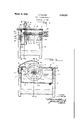
- Fig. 1 is a vertical transverse section of the machine on the line 11 of Fig. 2.
- Fig. 2 is a longitudinal vertical section of the machine on the line 22 of Fig. 1.
- the machine is provided with a frame 10 substantially rectangular in form and having a table 11 with a'metallic surface 12, longi- 3 tudinal bars 13, 14 and 15 and cross bars 16,
- a rotary cutter is mounted on a shaft 20 mounted transversely in the machine in bearings 21 and 22 mounted on the bars 13 and 14 and driven by a pulley 23 secured thereon.
- the rotary cutter is mounted on the inner end of the shaft 20 and consists of a hub 25, a metal disk 26 and an annular emery cutter 27 secured on the periphery of said disk 26, as shown.
- the hub 25 of the cutter is mounted on a reduced portion 28 of the shaft 20 and clamped thereon by the nut 29.
- the rotary cutter is mounted so that the upper portion thereof will project through a slot 30 in the table 11, as shown, much like rotary saws are mounted.
- the water tank is secured in the frame between the bars 14 and 15 and below the table 11, so that the cutter will operate therein, as shown.
- This tank is filled about half full .the water deflector.
- the main part of the frame composed of the parts 10, 13, 14, 15, 17'and 19 is stationary and the water tank 35 is mounted therein and extends appreciably higher than said stationary frame, as shown in Fig. 1, and it also extends from front to rear or longitudinally of said frame.
- the bearings of the cutter are mounted on the sta tionary part of the frame as seen also in Fig. 1.
- the upper part of the frame consisting of the table 11 and cross bars 16 and 18 are hinged at the rear end of the machine on cross bar 17 so that its front end can be lifted and said upper part of the frame tilted upward by the workmen standing at the front end of the machine, and at that end the table projects as shown in Fig. 2. This furnishes easy access to the water tank and to the cutter.
- Roof tile is generally cut diagonally to adapt the portions thereof to the hip or the valley of the roof.
- the tile is placed upon the table 11 and fed to the cutter much in the same way as wooden boards are hand fed to rotary saws, the cutter turning in the direction indicated by the arrow in Fig. 2.
- the cutting portion 27 of the cutter, the emery portion, is usually about one-fourth inch thick so that it cuts substantially a onefourth inch kerf.
- a water deflector 40 is mounted above the cutter substantially as shown, by means of an arm. 41 that is secured by bolts to the frame bar 16 at the rear end of the hinged part of p the frame and extends forwardly as shown in Fig. 2.
- the water deflector has an upper wall concavely curved longitudinally and forwardly of the machine and the cutter, and it has side walls 42 parallel with each other and extending downward to .a point slightly below the upper edge of the cutter, so that the upper edge of the cutter, in a sense, runs in Also the deflector is turned downwardly and somewhat rearwardly in the form of a lip at the front end thereof, as seen in Fig. 2.
- the deflector is such as to concentrate and direct the water on the cutter and prevent water being thrown too far forward against the workmen by the cutter. Since the periphery of the cutter is made of emery or like material and is therefore relatively thick and porous, as distinguished from a metal cutter, it will throw and direct an ample quantity of water upon the tile which is located on the table in front of the cutter. lVhile it is being cut thus both the cutters and the tile are kept water-soaked sufiiciently and amply and the workman is' i to the cutter.
- the table 11 is depressed at 43 near the cutter slot 30 and on each side thereof, as shown in Fig. 1, and there are also a number of drainage holes 44 in said depressed portion. This is for the purpose of facilitating the drainage or return of the water that is carried upward by the cutter and deflected by the water deflector l0.
- a splash plate 45 secured to the under side of the table 11 around said perforations and depression and extends into the upper end of the tank for guiding the water back to the tank and preventing the water splashing out over the top of the tank.
- a machine for cutting tile and the like having a stationary frame, a water tank mounted therein with its top open, a vertically disposed rotary cutter having its periphery formed of emery and the like and mounted in the machine so that the lower portion thereof will run in the water in the tank and the upper portion thereof will extend above the tank, an upper portion of the frame including a table which portion is hinged at the rear end to the stationary portion of the frame and arranged so that the front end thereof may be lifted and tilted upward and backward and the table thereof being provided with a slot through which the upper part of the cutter projects, and a water deflector secured at the rear end of said up per part of the frame and extending forward and free above the cutter with the sides and front end thereof extending below the upper edge of the cutter for concentrating the water which is thrown upward against said reflector down on the cutter, substantially as set forth.
- a machine for cutting tile and the like substantially as set forth in claim 1 with the water tank extending above the stationary part of the frame, and a splash plate secured to the under side of the table and extending down into the water tank with suflicient clearance between said splash plate and the water tank to permit the tilting upward and backward of the upper part of the frame including the table and water deflector substantially as set forth.
- a machine for cutting tile and the like including a slotted table, a vertically disposed rotary cutter mounted below the table with its upper and operating portion extending through the slot in the table, a water tank located below the table, the lower portion of the cutter running in the water whereby water will be carried up by the cutter for wetting the cutter and tile, and an overhanging combination guard and water deflector, mounted above the table and cutter with its sides and ends extending below the upper edge of the cutter for deflecting the water which is thrown upward against said deflector down on the cutter whereby said cutter will be kept wet and the tile being cut will also be kept wet by said wet cutter, said guard overhang portion projecting from one side of the cutter to beyond the axis thereof, and having its sides in spaced relation to the table for work reception therebetween.
- a slotted work supporting table a liquid containing tank therebeneath, a rotary cutter rotatably mounted beneath the table and above the tank and having its lower portion projecting into the tank and its upper portion projecting through the table slot for cutting, and an overhanging combination work and splash guard projecting upwardly from the table adjacent one end of the table slot and including an overhanging portion extending toward the cutter to beyond the cutter axis but spaced from the table for confining the splashing from the cutter and returning the discharge to the cutter and to the tank.
Landscapes
- Engineering & Computer Science (AREA)
- Mechanical Engineering (AREA)
- Mining & Mineral Resources (AREA)
- Processing Of Stones Or Stones Resemblance Materials (AREA)
Description
Patented Mar. 18, 1930 UNITED STATES PATENT OFFICE OTTO WALTER, OF PERRYSVILLE, INDIANA TILE-CUTTING MACHINE Application filed October 3, 1927. Serial No. 223,598.
The object of this invention is the making of a machine for practically and successfully cutting roof tile and the like, such as concrete tile, clay tile or tile made of any material of the same general character.
Another object of said machine is to minimize or avoid waste as by this machine both parts of a cut tile is capable of use, one on the hip of the roof and one in the valley,
whereas heretofore only one part has been capable of use, the other being in broken pieces that had to be thrown away.
Another object of the invention is to provide such a machine as a common laborer can operate successfully, because of its simplicity, and still another object is to provide a very smooth cut surface instead of a ragged broken edge.
The features of the invention will be understood from the accompanying drawings and the following description and claims.
In the drawings Fig. 1 is a vertical transverse section of the machine on the line 11 of Fig. 2. Fig. 2 is a longitudinal vertical section of the machine on the line 22 of Fig. 1.
The machine is provided with a frame 10 substantially rectangular in form and having a table 11 with a'metallic surface 12, longi- 3 tudinal bars 13, 14 and 15 and cross bars 16,
'17, 18 and 19.
A rotary cutter is mounted on a shaft 20 mounted transversely in the machine in bearings 21 and 22 mounted on the bars 13 and 14 and driven by a pulley 23 secured thereon. The rotary cutter is mounted on the inner end of the shaft 20 and consists of a hub 25, a metal disk 26 and an annular emery cutter 27 secured on the periphery of said disk 26, as shown. The hub 25 of the cutter is mounted on a reduced portion 28 of the shaft 20 and clamped thereon by the nut 29.
The rotary cutter is mounted so that the upper portion thereof will project through a slot 30 in the table 11, as shown, much like rotary saws are mounted.
The water tank is secured in the frame between the bars 14 and 15 and below the table 11, so that the cutter will operate therein, as shown. This tank is filled about half full .the water deflector.
of water, that is, so that the water will extend up almost to the hub of the cutter. This is for the purpose of keeping the cutter wet and also keeping the tile wet while it is being out.
It is noted that the main part of the frame composed of the parts 10, 13, 14, 15, 17'and 19 is stationary and the water tank 35 is mounted therein and extends appreciably higher than said stationary frame, as shown in Fig. 1, and it also extends from front to rear or longitudinally of said frame. The bearings of the cutter are mounted on the sta tionary part of the frame as seen also in Fig. 1. The upper part of the frame consisting of the table 11 and cross bars 16 and 18 are hinged at the rear end of the machine on cross bar 17 so that its front end can be lifted and said upper part of the frame tilted upward by the workmen standing at the front end of the machine, and at that end the table projects as shown in Fig. 2. This furnishes easy access to the water tank and to the cutter.
Roof tile is generally cut diagonally to adapt the portions thereof to the hip or the valley of the roof. The tile is placed upon the table 11 and fed to the cutter much in the same way as wooden boards are hand fed to rotary saws, the cutter turning in the direction indicated by the arrow in Fig. 2. The cutting portion 27 of the cutter, the emery portion, is usually about one-fourth inch thick so that it cuts substantially a onefourth inch kerf. V
A water deflector 40 is mounted above the cutter substantially as shown, by means of an arm. 41 that is secured by bolts to the frame bar 16 at the rear end of the hinged part of p the frame and extends forwardly as shown in Fig. 2. The water deflector has an upper wall concavely curved longitudinally and forwardly of the machine and the cutter, and it has side walls 42 parallel with each other and extending downward to .a point slightly below the upper edge of the cutter, so that the upper edge of the cutter, in a sense, runs in Also the deflector is turned downwardly and somewhat rearwardly in the form of a lip at the front end thereof, as seen in Fig. 2. Therefore the deflector is such as to concentrate and direct the water on the cutter and prevent water being thrown too far forward against the workmen by the cutter. Since the periphery of the cutter is made of emery or like material and is therefore relatively thick and porous, as distinguished from a metal cutter, it will throw and direct an ample quantity of water upon the tile which is located on the table in front of the cutter. lVhile it is being cut thus both the cutters and the tile are kept water-soaked sufiiciently and amply and the workman is' i to the cutter.
The table 11 is depressed at 43 near the cutter slot 30 and on each side thereof, as shown in Fig. 1, and there are also a number of drainage holes 44 in said depressed portion. This is for the purpose of facilitating the drainage or return of the water that is carried upward by the cutter and deflected by the water deflector l0. There is also a splash plate 45 secured to the under side of the table 11 around said perforations and depression and extends into the upper end of the tank for guiding the water back to the tank and preventing the water splashing out over the top of the tank.
lVater is required to keep the cutter and tile wet and dustless. Dry tile is so very hard that it is impractical to cut it unless it is softened by being saturated with water. The water also facilitates the cutting of the emery and particularly keeps it from heating and prolongs its life. When the hinged upper portion of the frame is moved upward and backward by the workmen lifting the front part thereof, it carries with it both the deflector l0 and the splash plate 45, which is secured thereto. This is permitted by ample clearance being provided between the splash plate 40 and the wall of the water plate 35, as shown in Fig. 2.
The invention claimed is:
1. A machine for cutting tile and the like having a stationary frame, a water tank mounted therein with its top open, a vertically disposed rotary cutter having its periphery formed of emery and the like and mounted in the machine so that the lower portion thereof will run in the water in the tank and the upper portion thereof will extend above the tank, an upper portion of the frame including a table which portion is hinged at the rear end to the stationary portion of the frame and arranged so that the front end thereof may be lifted and tilted upward and backward and the table thereof being provided with a slot through which the upper part of the cutter projects, and a water deflector secured at the rear end of said up per part of the frame and extending forward and free above the cutter with the sides and front end thereof extending below the upper edge of the cutter for concentrating the water which is thrown upward against said reflector down on the cutter, substantially as set forth.
2. A machine for cutting tile and the like substantially as set forth in claim 1 with the water tank extending above the stationary part of the frame, and a splash plate secured to the under side of the table and extending down into the water tank with suflicient clearance between said splash plate and the water tank to permit the tilting upward and backward of the upper part of the frame including the table and water deflector substantially as set forth.
3. A machine for cutting tile and the like including a slotted table, a vertically disposed rotary cutter mounted below the table with its upper and operating portion extending through the slot in the table, a water tank located below the table, the lower portion of the cutter running in the water whereby water will be carried up by the cutter for wetting the cutter and tile, and an overhanging combination guard and water deflector, mounted above the table and cutter with its sides and ends extending below the upper edge of the cutter for deflecting the water which is thrown upward against said deflector down on the cutter whereby said cutter will be kept wet and the tile being cut will also be kept wet by said wet cutter, said guard overhang portion projecting from one side of the cutter to beyond the axis thereof, and having its sides in spaced relation to the table for work reception therebetween.
4. In combination a slotted work supporting table, a liquid containing tank therebeneath, a rotary cutter rotatably mounted beneath the table and above the tank and having its lower portion projecting into the tank and its upper portion projecting through the table slot for cutting, and an overhanging combination work and splash guard projecting upwardly from the table adjacent one end of the table slot and including an overhanging portion extending toward the cutter to beyond the cutter axis but spaced from the table for confining the splashing from the cutter and returning the discharge to the cutter and to the tank.
In witness whereof, I have hereunto affixed my signature.
OTTO WALTER.
Priority Applications (1)
| Application Number | Priority Date | Filing Date | Title |
|---|---|---|---|
| US223598A US1750737A (en) | 1927-10-03 | 1927-10-03 | Tile-cutting machine |
Applications Claiming Priority (1)
| Application Number | Priority Date | Filing Date | Title |
|---|---|---|---|
| US223598A US1750737A (en) | 1927-10-03 | 1927-10-03 | Tile-cutting machine |
Publications (1)
| Publication Number | Publication Date |
|---|---|
| US1750737A true US1750737A (en) | 1930-03-18 |
Family
ID=22837195
Family Applications (1)
| Application Number | Title | Priority Date | Filing Date |
|---|---|---|---|
| US223598A Expired - Lifetime US1750737A (en) | 1927-10-03 | 1927-10-03 | Tile-cutting machine |
Country Status (1)
| Country | Link |
|---|---|
| US (1) | US1750737A (en) |
Cited By (5)
| Publication number | Priority date | Publication date | Assignee | Title |
|---|---|---|---|---|
| US2444598A (en) * | 1947-06-16 | 1948-07-06 | Wilfred C Eyles | Tile-sawing machine |
| FR2497717A1 (en) * | 1981-01-13 | 1982-07-16 | Goubaud Michel | Circular saw with water bath - is mounted in water level regulated case with inlet controlled by pivotable flap |
| CN105215827A (en) * | 2015-09-29 | 2016-01-06 | 安徽省宁国市天成科技发展有限公司 | A kind of Multifunctional heating pipe pipe installation |
| US10252444B2 (en) | 2017-04-14 | 2019-04-09 | Tti (Macao Commercial Offshore) Limited | Tile saw |
| US20210387377A1 (en) * | 2015-12-16 | 2021-12-16 | Black & Decker Inc. | Tile saw |
-
1927
- 1927-10-03 US US223598A patent/US1750737A/en not_active Expired - Lifetime
Cited By (6)
| Publication number | Priority date | Publication date | Assignee | Title |
|---|---|---|---|---|
| US2444598A (en) * | 1947-06-16 | 1948-07-06 | Wilfred C Eyles | Tile-sawing machine |
| FR2497717A1 (en) * | 1981-01-13 | 1982-07-16 | Goubaud Michel | Circular saw with water bath - is mounted in water level regulated case with inlet controlled by pivotable flap |
| CN105215827A (en) * | 2015-09-29 | 2016-01-06 | 安徽省宁国市天成科技发展有限公司 | A kind of Multifunctional heating pipe pipe installation |
| US20210387377A1 (en) * | 2015-12-16 | 2021-12-16 | Black & Decker Inc. | Tile saw |
| US10252444B2 (en) | 2017-04-14 | 2019-04-09 | Tti (Macao Commercial Offshore) Limited | Tile saw |
| US11554517B2 (en) * | 2017-04-14 | 2023-01-17 | Techtronic Power Tools Technology Limited | Tile saw |
Similar Documents
| Publication | Publication Date | Title |
|---|---|---|
| US1662372A (en) | Saw guard | |
| US4334356A (en) | Anti-mar base for saber- and bayonet-type saws and the like | |
| US2998813A (en) | Masonry saw | |
| US1830151A (en) | Dust collector and guard for saws | |
| EP0830912A3 (en) | Table saw | |
| JP3813224B2 (en) | Flat ground crusher with replaceable knife and wear plate | |
| US1750737A (en) | Tile-cutting machine | |
| US3189064A (en) | Saw chain | |
| US8347871B2 (en) | Wet cutting saw | |
| US2716402A (en) | Masonry cutting machine | |
| US2839100A (en) | Woodworking accessory | |
| US2444598A (en) | Tile-sawing machine | |
| US5460068A (en) | Apparatus for cutting ice cakes into blocks | |
| US3970125A (en) | Tree cutting apparatus | |
| USRE23650E (en) | Rechippeb with vibrating trough | |
| US2664923A (en) | Machine for splitting or resawing insulating boards | |
| US3726565A (en) | Material stripping apparatus and blade | |
| US1801721A (en) | Table top for portable saws | |
| US2340553A (en) | Abrasive cutoff machine | |
| US4709609A (en) | Saw machine | |
| US518655A (en) | Theodore f | |
| US2685311A (en) | Method for splitting or resawing insulating board | |
| US3056325A (en) | Cutting apparatus having a reciprocating tool carriage and stopping means | |
| US2966182A (en) | Lumber blanking and chipping machine | |
| US2938553A (en) | Knife mounting for planer chippers |