US1745546A - Ignition timer and distributor - Google Patents
Ignition timer and distributor Download PDFInfo
- Publication number
- US1745546A US1745546A US22982A US2298225A US1745546A US 1745546 A US1745546 A US 1745546A US 22982 A US22982 A US 22982A US 2298225 A US2298225 A US 2298225A US 1745546 A US1745546 A US 1745546A
- Authority
- US
- United States
- Prior art keywords
- housing
- distributor
- timer
- opening
- bottom wall
- Prior art date
- Legal status (The legal status is an assumption and is not a legal conclusion. Google has not performed a legal analysis and makes no representation as to the accuracy of the status listed.)
- Expired - Lifetime
Links
Images
Classifications
-
- F—MECHANICAL ENGINEERING; LIGHTING; HEATING; WEAPONS; BLASTING
- F02—COMBUSTION ENGINES; HOT-GAS OR COMBUSTION-PRODUCT ENGINE PLANTS
- F02P—IGNITION, OTHER THAN COMPRESSION IGNITION, FOR INTERNAL-COMBUSTION ENGINES; TESTING OF IGNITION TIMING IN COMPRESSION-IGNITION ENGINES
- F02P5/00—Advancing or retarding ignition; Control therefor
- F02P5/02—Advancing or retarding ignition; Control therefor non-automatically; dependent on position of personal controls of engine, e.g. throttle position
Definitions
- This invention relates to ignition timing and distributing apparatus and one of the objects of the invention is to provide a durable and reliable ignition timer which can be manufactured at relatively low cost.
- Fig. l is a longitudinal sectional view of a timer-distributor embodying the present invention. The section through the timer is taken substantially on the line 11 of Fig. 3;
- Fig. 2 is a plan view thereof
- Fig. 3 is a plan view of the timer with the distributor head removed;
- Fig. 4 is a fragmentary side view showing the member which provides a name plate for the apparatus and also serves as the insulated terminal of the timer. Fig. 4 is taken looking in the direction of the arrow 4 in Fig. 3;
- Figs. 5, 6, 7 and 8 are sectional views taken respectively on lines 5-5, 6-6, 77 and 88 of Fig. 3;
- Fig. 9 is a sectional view on the line 99 of Fig. 2.
- the apparatus includes a platform member 20, provided with a tubular shank 21 for supporting a cam shaft 22.
- Shaft 22 carries at its lower end a washer 23 and a gear 24, which is attached by a pin 25.
- a washer 26 which is swedged into a groove27 provided in the shaft 22 is received by a suitable recess provided by the platform 20.
- the shank 21 and the platform 20 are, therefore, confined between the washers 23 and 26, thereby limiting endwise movement of the shaft 22.
- the recess which receives the washer 26 is provided by an annular boss 28, the exterior 'of which provides a bearing for the bottom wall 29 of a timer housing 30.
- the bottom wall 29 is provided with arcuate slots 31 and screws 32 pass through the slots and through tapped holes in the platform 20.
- - dished washers 33 are located between the heads of the screws 32 and the bottom wall of the timer housing in order to hold the bottom wall 29 resiliently in contact with an annular boss 34 provided by the platform 20.
- the screws 32 are held in adjusted position by nuts 35 and lock Washers 36.
- the housing 30 is manipulated by an L-shaped lever 37, one leg of which is attached by a rivet 38 to the inside of the housing 30, the other leg of which passes through a notch 39 and extends horizontally to the exterior of the housing 30.
- the shaft 22 is provided with a tapered portion 40 for receiving the timer cam 41 having a correspondingly tapered bore for receiving the tapered portion 40.
- the cam is provided with diametrically opposite notches 42, for receiving lugs 43 extending from a washer '44 which surrounds the shaft 22.
- a nut 45 engages a threaded portion 46 of the shaft for securing the cam 41 and the washer 44 in correct position of adjustment.
- the reduced upper end 47 of the cam shaft 22 receivesa distributor rotor 48 having a notch 49 for receiving a projection 50 which extends upwardly from the washer 44.
- the rotor 48 carries a resilient center Contact 51 attached by a rivet 52, embedded in the material of the rotor, to a distributor segment 53.
- Segment 53 cooperates with a circular row of distributor posts 54 and the center contact 51 resiliently bears against a button 55 supported by a receptacle 56 embedded in the molded material of the distributor head 57.
- the posts 54 are provided with knurled portions 58 which can be driven into inserts 59 also embedded in the distributor head.
- the posts 54 and the center button 55 are provided with pointed ends 54 and 55 which extend within cable-receiving sockets 60 and 1611, aespectively, provided by the distributor Head 57 is provided with an annular groove 62 and a flange 62' which are received by the circular upper edge 63 of the housing 30.
- the flange 62 is provided with a notch 39 for receiving the handle 37, the handle and notch cooperating to locate the head 57 in correct angular position with respect to the housing 30.
- the head 57. is retained in position by two spring clips 64 having hook portions 65 which are received by sockets 66 provided by the distributor head. The hook portions spring over shoulders 67 before moving into the sockets 66.
- the bottom wall 29 of the timer housing 30 is notched at 68 to receive the lower end of a spring clip 64 which extends around the edge of the bottom wall 29 and then upwardly through an opening 69 provided therein by punching away'a portion of the bottom wall to provide the opening and to form a lip 70.
- the spring clip 64 cannot be removed.
- the timer cam 41 cooperates with a rubbing block 71 which is attached by a rivet 72 to a breaker lever 73 which has a non-conducting hub 74 supported by a stud 75 mounted on the bottom wall 29.
- the hub 74 is retained on the stud 75 by a clip 76 which may be sprung in the'groove provided in the stud 75.
- the rivet 72 also secures between the lever 73 and the rubbing block 71, an end of a leaf spring 77 having its intermediate portion partly encircling the hub of the lever and having its other end, indicated at 78, in Fig.
- the plate 82 is secured by rivets 84 to the housing 30 and is insulated from the cup by a non-conducting plate 85 which surrounds the opening 83.
- the rivets 84 are each in- Sulated from the housing 30 by providing holes' in the housing 30 which are larger than the shanks of the rivets, and by providing non-conducting washers 86, between the' heads of the rivets and. the inside of the housing 30.
- the plate 82 not only serves as a 'cover for the opening 83 but also provides. space for the name of the manufacture;-
- the bracket 94 is pivotally mounted upon the bottom wall 29 of the timer housing 30 by a rivet 96, and the bracket 94 is secured in various positions of adjustment by a screw 97 which passes through a slot 98 in the bracket 94 and engages a hole tapped in the plate 29.
- an L-shaped handle for moving the cup, said handle having one leg attached to the interior cylindrical wall of the housing and the other leg extending outwardly from the housing, and a distributor head having a circular flange telescopically engaged by therim of the housing, the flange having a notch for receiving the L-shaped handle and in which the handle snugly fits, whereby the handle and notch provide means for positively locating the distributor head on the housing and the notch provides clearance for the leg of the handle which extends outwardly from the housing.
- An ignition timer comprising, in combination, a cylindrical housing having an opening through the side thereof,- a cover plate for the opening insulatingly supported by the housing and providing a terminal, a breaker lever within the housing, and a spring mechanically and electrically connected with the lever and with said cover plate.
- An ignition timer comprising, in combination, a cylindrical housing having an opening through the side thereof, a cover plate for the opening insulatingly supported by the housing and providing a terminal, a circuit interrupter within the housing, and aconductor connected with the interrupter and with said cover plate.
Landscapes
- Engineering & Computer Science (AREA)
- Chemical & Material Sciences (AREA)
- Combustion & Propulsion (AREA)
- Mechanical Engineering (AREA)
- General Engineering & Computer Science (AREA)
- Measurement Of Predetermined Time Intervals (AREA)
Description
Feb. 4, 1930. I c, KROEGER 1,745,546
IGNITION TIMER AND DISTRIBUTOR Filed April 14, 1925 i atented F eb. 4, 1930 UNITED STATES PATENT OFFICE FREDERICK G. KROEGER, OF ANDERSON, INDIANA, ASSIGNOR, BY MESNE ASSIGN- MENTS, TO DELCO-REMY CORPORATION, OF DAYTON, OHIO, A CORPORATION OF DELAWARE IGNITION TIMER AND DISTRIBUTOR Application filed April 14, 1925.- Serial No. 22,982.
This invention relates to ignition timing and distributing apparatus and one of the objects of the invention is to provide a durable and reliable ignition timer which can be manufactured at relatively low cost.
Further objects and advantages of the present invention will be apparent from the following description, reference being had to the accompanying drawings, wherein a preferred form of embodiment of the present invention is clearly shown.
In the drawings:
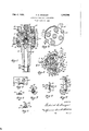
Fig. l is a longitudinal sectional view of a timer-distributor embodying the present invention. The section through the timer is taken substantially on the line 11 of Fig. 3;
Fig. 2 is a plan view thereof;
Fig. 3 is a plan view of the timer with the distributor head removed;
Fig. 4 is a fragmentary side view showing the member which provides a name plate for the apparatus and also serves as the insulated terminal of the timer. Fig. 4 is taken looking in the direction of the arrow 4 in Fig. 3;
Figs. 5, 6, 7 and 8 are sectional views taken respectively on lines 5-5, 6-6, 77 and 88 of Fig. 3;
Fig. 9 is a sectional view on the line 99 of Fig. 2.
The apparatus includes a platform member 20, provided with a tubular shank 21 for supporting a cam shaft 22. Shaft 22 carries at its lower end a washer 23 and a gear 24, which is attached by a pin 25. A washer 26 which is swedged into a groove27 provided in the shaft 22 is received by a suitable recess provided by the platform 20. The shank 21 and the platform 20 are, therefore, confined between the washers 23 and 26, thereby limiting endwise movement of the shaft 22. The recess which receives the washer 26 is provided by an annular boss 28, the exterior 'of which provides a bearing for the bottom wall 29 of a timer housing 30. The bottom wall 29 is provided with arcuate slots 31 and screws 32 pass through the slots and through tapped holes in the platform 20. Resilient,
- dished washers 33 are located between the heads of the screws 32 and the bottom wall of the timer housing in order to hold the bottom wall 29 resiliently in contact with an annular boss 34 provided by the platform 20. The screws 32 are held in adjusted position by nuts 35 and lock Washers 36. The housing 30 is manipulated by an L-shaped lever 37, one leg of which is attached by a rivet 38 to the inside of the housing 30, the other leg of which passes through a notch 39 and extends horizontally to the exterior of the housing 30.
The shaft 22 is provided with a tapered portion 40 for receiving the timer cam 41 having a correspondingly tapered bore for receiving the tapered portion 40. The cam is provided with diametrically opposite notches 42, for receiving lugs 43 extending from a washer '44 which surrounds the shaft 22. A nut 45 engages a threaded portion 46 of the shaft for securing the cam 41 and the washer 44 in correct position of adjustment. The reduced upper end 47 of the cam shaft 22 receivesa distributor rotor 48 having a notch 49 for receiving a projection 50 which extends upwardly from the washer 44. The rotor 48 carries a resilient center Contact 51 attached by a rivet 52, embedded in the material of the rotor, to a distributor segment 53. Segment 53 cooperates with a circular row of distributor posts 54 and the center contact 51 resiliently bears against a button 55 supported by a receptacle 56 embedded in the molded material of the distributor head 57. The posts 54 are provided with knurled portions 58 which can be driven into inserts 59 also embedded in the distributor head. The posts 54 and the center button 55 are provided with pointed ends 54 and 55 which extend within cable-receiving sockets 60 and 1611, aespectively, provided by the distributor Head 57 is provided with an annular groove 62 and a flange 62' which are received by the circular upper edge 63 of the housing 30. The flange 62 is provided with a notch 39 for receiving the handle 37, the handle and notch cooperating to locate the head 57 in correct angular position with respect to the housing 30. The head 57. is retained in position by two spring clips 64 having hook portions 65 which are received by sockets 66 provided by the distributor head. The hook portions spring over shoulders 67 before moving into the sockets 66. The bottom wall 29 of the timer housing 30 is notched at 68 to receive the lower end of a spring clip 64 which extends around the edge of the bottom wall 29 and then upwardly through an opening 69 provided therein by punching away'a portion of the bottom wall to provide the opening and to form a lip 70. As will be apparent from the Fig. 9, as long as the housing 30 is maintained upon the platform 20, the spring clip 64 cannot be removed.
The timer cam 41 cooperates with a rubbing block 71 which is attached by a rivet 72 to a breaker lever 73 which has a non-conducting hub 74 supported by a stud 75 mounted on the bottom wall 29. The hub 74 is retained on the stud 75 by a clip 76 which may be sprung in the'groove provided in the stud 75. The rivet 72 also secures between the lever 73 and the rubbing block 71, an end of a leaf spring 77 having its intermediate portion partly encircling the hub of the lever and having its other end, indicated at 78, in Fig. 7, attached by a screw 79 and a nut 80 to a non-conducting block 81 and to a plate 82, which serves as a cover for an'opening 83 provided in the side wall of the housing 30. The opening 83 provides clearance between parts Sland 77 and the timer housing. The plate 82 is secured by rivets 84 to the housing 30 and is insulated from the cup by a non-conducting plate 85 which surrounds the opening 83. The rivets 84 are each in- Sulated from the housing 30 by providing holes' in the housing 30 which are larger than the shanks of the rivets, and by providing non-conducting washers 86, between the' heads of the rivets and. the inside of the housing 30. The plate 82 not only serves as a 'cover for the opening 83 but also provides. space for the name of the manufacture;-
and is also a conducting member for connectengaging a stationary contact 91 carried on an adjusting screw 92 which is threaded into an ear 93 provided by a bracket 94. The screw 92 is maintained in adjusted position by a lock nut 95.: In order'to adjust the sur,.
face of the contact 91 to the surface of the contact 90, the bracket 94 is pivotally mounted upon the bottom wall 29 of the timer housing 30 by a rivet 96, and the bracket 94 is secured in various positions of adjustment by a screw 97 which passes through a slot 98 in the bracket 94 and engages a hole tapped in the plate 29.
tatably supported by the base, an L-shaped handle for moving the cup, said handle having one leg attached to the interior cylindrical wall of the housing and the other leg extending outwardly from the housing, and a distributor head having a circular flange telescopically engaged by therim of the housing, the flange having a notch for receiving the L-shaped handle and in which the handle snugly fits, whereby the handle and notch provide means for positively locating the distributor head on the housing and the notch provides clearance for the leg of the handle which extends outwardly from the housing.
2. An ignition timer comprising, in combination, a cylindrical housing having an opening through the side thereof,- a cover plate for the opening insulatingly supported by the housing and providing a terminal, a breaker lever within the housing, and a spring mechanically and electrically connected with the lever and with said cover plate.
3. An ignition timer comprising, in combination, a cylindrical housing having an opening through the side thereof, a cover plate for the opening insulatingly supported by the housing and providing a terminal, a circuit interrupter within the housing, and aconductor connected with the interrupter and with said cover plate.
In testimony whereof I hereto aifix my signature.
FREDERICK C. KROEGER.
While the form of embodiment of the present invention as herein disclosed, constitutes
Priority Applications (1)
| Application Number | Priority Date | Filing Date | Title |
|---|---|---|---|
| US22982A US1745546A (en) | 1925-04-14 | 1925-04-14 | Ignition timer and distributor |
Applications Claiming Priority (1)
| Application Number | Priority Date | Filing Date | Title |
|---|---|---|---|
| US22982A US1745546A (en) | 1925-04-14 | 1925-04-14 | Ignition timer and distributor |
Publications (1)
| Publication Number | Publication Date |
|---|---|
| US1745546A true US1745546A (en) | 1930-02-04 |
Family
ID=21812447
Family Applications (1)
| Application Number | Title | Priority Date | Filing Date |
|---|---|---|---|
| US22982A Expired - Lifetime US1745546A (en) | 1925-04-14 | 1925-04-14 | Ignition timer and distributor |
Country Status (1)
| Country | Link |
|---|---|
| US (1) | US1745546A (en) |
-
1925
- 1925-04-14 US US22982A patent/US1745546A/en not_active Expired - Lifetime
Similar Documents
| Publication | Publication Date | Title |
|---|---|---|
| US2790020A (en) | Ignition apparatus | |
| US2727104A (en) | Contact assembly | |
| US2546710A (en) | Breaker plate assembly for distributors | |
| US1745546A (en) | Ignition timer and distributor | |
| US2187070A (en) | Ignition distributor | |
| US2874254A (en) | Variable resistor with a plug-in mounting | |
| US2797269A (en) | buck ctal | |
| US2717286A (en) | Stabilizing device | |
| US2816968A (en) | Distributor structure | |
| US2678365A (en) | Ignition distributor | |
| US2219480A (en) | Centrifugal control for ignition timer | |
| US2914625A (en) | Ignition breaker assembly | |
| US1766908A (en) | Ignition timer | |
| US1795937A (en) | To north east | |
| US1708225A (en) | Aflsignor | |
| US3091672A (en) | Ignition distributor | |
| USRE18276E (en) | of dayton | |
| US1825720A (en) | Asskjnob to delco-bemy cobfoba | |
| US1864459A (en) | norviel | |
| US2542411A (en) | Circuit breaker | |
| US1981041A (en) | Ignition apparatus | |
| US3833777A (en) | Pre-gapped breaker point assemblies | |
| US2579928A (en) | Primary ignition system | |
| US1641352A (en) | Electric switch | |
| US2873324A (en) | Distributor mechanism |