US1745524A - Method of and apparatus for machining valves, etc. - Google Patents
Method of and apparatus for machining valves, etc. Download PDFInfo
- Publication number
- US1745524A US1745524A US38172A US3817225A US1745524A US 1745524 A US1745524 A US 1745524A US 38172 A US38172 A US 38172A US 3817225 A US3817225 A US 3817225A US 1745524 A US1745524 A US 1745524A
- Authority
- US
- United States
- Prior art keywords
- valve
- cradle
- axis
- machining
- jig
- Prior art date
- Legal status (The legal status is an assumption and is not a legal conclusion. Google has not performed a legal analysis and makes no representation as to the accuracy of the status listed.)
- Expired - Lifetime
Links
- 238000003754 machining Methods 0.000 title description 20
- 238000000034 method Methods 0.000 title description 7
- 238000005266 casting Methods 0.000 description 13
- 238000010276 construction Methods 0.000 description 4
- 229910000831 Steel Inorganic materials 0.000 description 2
- 238000005520 cutting process Methods 0.000 description 2
- 230000000717 retained effect Effects 0.000 description 2
- 239000010959 steel Substances 0.000 description 2
- 238000004519 manufacturing process Methods 0.000 description 1
- 239000000463 material Substances 0.000 description 1
- 238000005259 measurement Methods 0.000 description 1
- WUAPFZMCVAUBPE-UHFFFAOYSA-N rhenium atom Chemical compound [Re] WUAPFZMCVAUBPE-UHFFFAOYSA-N 0.000 description 1
Images

Classifications
-
- B—PERFORMING OPERATIONS; TRANSPORTING
- B23—MACHINE TOOLS; METAL-WORKING NOT OTHERWISE PROVIDED FOR
- B23C—MILLING
- B23C3/00—Milling particular work; Special milling operations; Machines therefor
- B23C3/02—Milling surfaces of revolution
- B23C3/05—Finishing valves or valve seats
-
- Y—GENERAL TAGGING OF NEW TECHNOLOGICAL DEVELOPMENTS; GENERAL TAGGING OF CROSS-SECTIONAL TECHNOLOGIES SPANNING OVER SEVERAL SECTIONS OF THE IPC; TECHNICAL SUBJECTS COVERED BY FORMER USPC CROSS-REFERENCE ART COLLECTIONS [XRACs] AND DIGESTS
- Y10—TECHNICAL SUBJECTS COVERED BY FORMER USPC
- Y10T—TECHNICAL SUBJECTS COVERED BY FORMER US CLASSIFICATION
- Y10T279/00—Chucks or sockets
- Y10T279/13—Angularly adjustable or indexing
-
- Y—GENERAL TAGGING OF NEW TECHNOLOGICAL DEVELOPMENTS; GENERAL TAGGING OF CROSS-SECTIONAL TECHNOLOGIES SPANNING OVER SEVERAL SECTIONS OF THE IPC; TECHNICAL SUBJECTS COVERED BY FORMER USPC CROSS-REFERENCE ART COLLECTIONS [XRACs] AND DIGESTS
- Y10—TECHNICAL SUBJECTS COVERED BY FORMER USPC
- Y10T—TECHNICAL SUBJECTS COVERED BY FORMER US CLASSIFICATION
- Y10T82/00—Turning
- Y10T82/26—Work driver
-
- Y—GENERAL TAGGING OF NEW TECHNOLOGICAL DEVELOPMENTS; GENERAL TAGGING OF CROSS-SECTIONAL TECHNOLOGIES SPANNING OVER SEVERAL SECTIONS OF THE IPC; TECHNICAL SUBJECTS COVERED BY FORMER USPC CROSS-REFERENCE ART COLLECTIONS [XRACs] AND DIGESTS
- Y10—TECHNICAL SUBJECTS COVERED BY FORMER USPC
- Y10T—TECHNICAL SUBJECTS COVERED BY FORMER US CLASSIFICATION
- Y10T82/00—Turning
- Y10T82/29—Attachment for cutting a valve
Definitions
- This invention is for a method of and apparatus for the machining of metallic articles such for example as castings for gate Valves and the like.
- the invention is especially applicable to the manufacture of gate valves of wedge-gate type, but it is not confined to this particular type of work.
- valve seats are inclined in opposite direc-.
- the nut 12 travels along the screw ratus being readily adjustable to present the surfaces to be machined in the proper plane and position.
- the invention further pertalns to a novel method for machining valves.
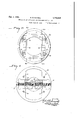
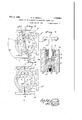
- Figure l is a side elevation of the apparatus showing the outline of a valve therein in broken lines, the valve being in position for the machining of the T-face thereof.
- Figure 2 is 2. shown in Fig. broken away.
- Figure 3 is a front end View of the apparatus, the valve being omitted.
- Figure 4 is a transverse section on the plane of line IV-IV of Fig. 2, showing a front elevation of the face plate.
- Figures 5 and 6 are views similar to a part of Fig. 2 but showing the valve turned to the two positions necessary for machining the two valve faces.
- Figure 7 is a detail view and a key therefor.
- FIG. 5 designates the end of a lathe shaft or the shaft of any other suitable machine, and 6 is a face plate carried thereon.
- a face plate secured to the face plate is the base 7 of a, cradle, designated generally as 8, the cradle being retained in position by bolts 9 passing through slots 7 in the base of the cradle.
- Loosening of the bolts 9 permits the cradle to be shifted to either side of the axis of rotation of the lathe, for the purpose hereinafter described.
- This adjustment can be made by turning a screw 10 extending across the face plate and having bearings therein at 11. On this screw is a nut 12 disposed between saddle like projections 13 on the base of the cradle.
- This general arrangement' can be best understood by reference to Figs. 2 and 4.
- the cradle laterally as may be desired.
- valve holder or jig 15 This jig, as best shown in Fig. 1, is a u-shaped construction having a yoke 15 at each end into which a rough This casting may be retained in place by renio'vabl'e clamping bars or strips 16' held in place by bolts 17.
- the axis of the trunnions for the jig must,'in the arrangement shown, be at right angles to the axis of the screw 10.
- sockets 18 and 18 in which are locking pins of similar construction.
- This construction includes an interiorly threaded hard steel bushing 19. Fitted into this threaded bushing is a threaded plug 20 having a downward extension 21 thereon, this extension passing centrally through a hard steel pin 22 having a conical end 22 A nut 21 on the extension 21 serves to hold the pin 22 on the extension 21.
- the upper face of plug 20 has a recess 20 therein with which a removable key' 23 may cooperate to raise the pinup and down by turning the plug.
- a shield 24 may be provided over the top of bushing 19.
- each of the sockets is preferably provided with a hardened bushing 29 having a conical opening therein.
- the valve hold ing jig may berotated on its trunnions and any of the holesf25. 26 or 27 be brought into register with the locking pin in socket 18, and any of the socket 25', 26',.o,r 27 brought into register with the pin in socket 18.
- these locking pins have'tapered ends, they cooperate with the conical openings in the bushings to accurately-center the locking pin in the bushing.
- a rough valve casting is fitted into the" jig 15 and bars 16 bolted on to retain the casting in place.
- the jig is properly shaped and dimensioned for the size otvalve with which it is to be used, and after the valve is clamped therein, it can have no relative movement in the jig.
- the symbol A designates the valve casting, which has the usual globe. like body with flanged or other snitablyshaped ends
- a Thro ughthe valve is the usual passage, and
- A designates the T on the valve body through which the gate operatesr
- the outer face, A, of this T is flanged, At. a and a" are the valve seats to be machined.
- the 'ig' holding cradle 8 is set so that the cradle is centered on the face plate and rotates concentrically.
- the jig is then turned, It may be assumed, to the position shown in Figs.
- Fig. 7 shows the locking pin prorotated 90 degrees. After being so rotated,
- the locking pin at 18 registers with socket 27, and may be entered into this socket to lock the jig.
- One -ot the ends A of the valve may be next lnachtmeltll.
- the valve is in the positio indicated in Fig. 5, where line cc indicates the axis of rotation of the lathe and the center line of the valve.
- the lathe is again operated with the valve so set, one of its end flanges A may be machlned. After this end has I been machined, the jig may be rotated '180 degrees and locked by the pin at 18 to present the other flange A to be machined.
- valve seats a and a" must be finished. As these valve seats are inclined in" opposite directionsfrom a plane perpendicular to the longitudinal axis of the valve, it is obvious that some special adjustment must be provided to machine these surfaces.
- the jig in which the valve is held is rotated through an are sufficient to bring one of the valve seats, say. a, as shown 1n Fig. 6, into a plane perpendicular to the axis of rotation of the lathe.
- This sets the longitudinal axis of-tho valve, c0, at an angle to the axis of rotation of the lathe d-d (Fig. 6) Therefore the seat a would rotate eccentrically about the axis ofrotation of the lathe.
- the jig could be moved through only a small arc, 1n which case afront cutterwould be used in machining one seat and a rear cutter used in machining the other.
- seat a" has been moved so that it is a plane perpendicular to the axis of rotation of the lathe, it is eccentric to the longitudinal axis of the valve and the cradle is shifted by operation of the screw 10 to the other side of the center of the face plate until the axis of rotation and the longitudinal axis of the valve coincide in the plane of the seat a".
- seat a" may be machined.
- an entirevalve casting can have all of the surfaces tobe finished machined in one lathe, and with but one setting of,the valve in the machine. It is not necessary or desirable to remove the valve after it is once set in the machine. All adjustments to present the difierent faces to the cutting tool can be quickly and conveniently made with absolute accuracy.
- Calibrations on the movable and stationary parts may be arranged to facilitate the making of adjustments. Furthermore, after the valve is once set in the jig, it does not matter if it is not initially on an absolutely centered position, taken out of the machine until after all faces have been machined, these faces will all bear the same proper relative relation to one another.
- a machine for the machining of valves and the like including a supporting member adapted for rotation, a unitary cradle memher on the supporting member and adjustable transversely with respect thereto, and a valve holding jig movable unitarily with the cradle member and rotatably carried in the cradle with its axis of rotation at right angles to the transverse direction of adjustment for the cradle, and means for adjustably holding the jig in various be rotated.
- A'machine for the finishing of valves and the like including a face plate adaptedfor rotation, a cradle carried by the face plate, means for moving the cradle transversely of the face plate, a valve holder rotatably carried in-the cradle and movable unitarily with the cradle, its axis of rotation being transverse to the direction of adjustment for the cradle, the transverse movement because, since it is notpositions to which it may of the cradle enabling the same valve to be located in a plurality of lateral ositions with respect to the axis of rotation 0 said plate.
- a machine of the class described for machining valves and the like including a face plate adapted for rotation, a cradle carried on the face plate, a screw for effecting plate, and means for adjustably holding the ig against relative rotatlon in the cradle.
- a machine for finishing valves having end faces, a T-face, and valve seats inclined with respect to the end faces in opposite 'directions, including a face plate adapted for rotation, a cradle adjustable transversely to the face plate, a jig pivotally carried in the cradle with its axis transverse to the direction in which the cradle may be adjusted and means for holding the jig against rotation for the machining of the end faces of a-valve, the
- a machine for finishing valves having oppositely inclined seat faces including a revoluble face plate, and a valve holder thereon adjustable to different an les with respect to the axis of rotation of the ace plate where by one or the other of the seats may be in a plane perpendicular to the axis of rotation of the face plate, said holder being also movable transversely of theface plate to cause the longitudinal axis of the valve to intersect the axis of rotationof the face plate in the plane of that valve seat which is perpendicular to the said axis of rotation.
Landscapes
- Engineering & Computer Science (AREA)
- Mechanical Engineering (AREA)
- Turning (AREA)
Description
R. W. BISSELL Feb. 4, 1930.
METHOD OF AND APPARATUS FOR MACHINING VALVES, ETC
5 Sheets-Shet Filed June 19, 1925 IN VEN TOR.
4S ATTORNEY Feb. 4, 1930. w, BISSELL' 1,745,524
METHOD OF AND APPARATUS FOR MACHINING VALVES, ETC
Filed June 19, 1925 3 Sheets-Sheet 2 I y L 7a ZLC f) nummmnnumuu1mmmumnu mmm I INVENTOR.
' ATTORNEY Feb. 4, 1930. R. w. BISSELL 1,745,524
METHOD OF AND APPARATUS FOR MACHINING VALVES, ETC
Filed June 19, 1925 3 Sheets-Sheet ATTORNEY Patented Feb. 4, 1930 UNITED STATE PATENT OFFICE ROBERT W. BISSELI, 0E PITTSBURGH, PENNSYLVANIA, ASSIGNOR T0 KEROTEST MAN- UFACTUBING COMPANY, .OF PITTSBURGH, PENNSYLVANIA, A CORPORATION OF PENNSYLVANIA OF AND APPARATUS FOR MACHINING- VALVES, ETC.
Application filed June 1;), 1925. Serial No. 38,172.
This invention is for a method of and apparatus for the machining of metallic articles such for example as castings for gate Valves and the like. The invention is especially applicable to the manufacture of gate valves of wedge-gate type, but it is not confined to this particular type of work.
' In the usual valve of the wedge-gate type,
the valve seats are inclined in opposite direc-.
tions at an angle to a plane perpendicular to the longitudinal axis of the valve. This requires, therefor, that in the making and in the repairing of these valves that the valve casting'be set in one position to turn'the square surfaces thereof and in other positions to successively machine the oppositely inclined valve seats.
The practice as ordinarily followed at the present time is to mount the valve casting in a lathe and machine the square surfacesthereof. Then the casting has to be secured to a wedge block on the face plate of a lathe so as to properly present one of the valve seats for machining. Having machined one valve seat, it has been the practice to remove the valve from its Wedgeplate, reverse it end for end, and again properly mount the valve on the wedge plate for the machining of the other Valve seat. This work of setting up the valve on a wedgeplate is very exacting and requires absolute accuracy of measurement. It is not only exacting and time consuming, but With'large heavy valves, it requires considerable manual labor.
In my co-pending application Serial No. 38,173 filed June 19, 1925, to which the present application is related, I have shown and described an apparatus wherein the casting, after having its square ends machined, can be conveniently mounted so as to bring one seat of the valve in position to be machined, and after such seat has been machined, slight adjustments may be made in the apparatus without disturbing the valve, to present the other seat in the proper plane.
According to the present invention I provide an apparatus in which the casting can be quickly secured, after'which all the surfaces,
' the nut 12 travels along the screw ratus being readily adjustable to present the surfaces to be machined in the proper plane and position. The invention further pertalns to a novel method for machining valves.
The nature of the invention may be readily understood by reference to the accompanying drawings, wherein Figure l is a side elevation of the apparatus showing the outline of a valve therein in broken lines, the valve being in position for the machining of the T-face thereof.
Figure 2 is 2. shown in Fig. broken away.
Figure 3 is a front end View of the apparatus, the valve being omitted.
Figure 4 is a transverse section on the plane of line IV-IV of Fig. 2, showing a front elevation of the face plate.
Figures 5 and 6 are views similar to a part of Fig. 2 but showing the valve turned to the two positions necessary for machining the two valve faces.
Figure 7 is a detail view and a key therefor.
In the drawings 5 designates the end of a lathe shaft or the shaft of any other suitable machine, and 6 is a face plate carried thereon. Secured to the face plate is the base 7 of a, cradle, designated generally as 8, the cradle being retained in position by bolts 9 passing through slots 7 in the base of the cradle. Loosening of the bolts 9 permits the cradle to be shifted to either side of the axis of rotation of the lathe, for the purpose hereinafter described. This adjustment can be made by turning a screw 10 extending across the face plate and having bearings therein at 11. On this screw is a nut 12 disposed between saddle like projections 13 on the base of the cradle. This general arrangement'can be best understood by reference to Figs. 2 and 4. When the screw 10 is rotated, by means of a suitable key or socket wrench,
1, part of the apparatus being of a locking pin,
the cradle laterally as may be desired.
Projecting forwardly from the base of the cradle are two arms 8 of-necessarylength. The ends of these arms have alined openings 8 therein in which are trunnion's 14. of a plan View of the arrangement to shift valve casting A may be set.
valve holder or jig 15. This jig, as best shown in Fig. 1, is a u-shaped construction having a yoke 15 at each end into which a rough This casting may be retained in place by renio'vabl'e clamping bars or strips 16' held in place by bolts 17. The axis of the trunnions for the jig must,'in the arrangement shown, be at right angles to the axis of the screw 10.
In one of the arms 8 are two sockets 18 and 18 in which are locking pins of similar construction. This construction includes an interiorly threaded hard steel bushing 19. Fitted into this threaded bushing is a threaded plug 20 having a downward extension 21 thereon, this extension passing centrally through a hard steel pin 22 having a conical end 22 A nut 21 on the extension 21 serves to hold the pin 22 on the extension 21. The upper face of plug 20 has a recess 20 therein with which a removable key' 23 may cooperate to raise the pinup and down by turning the plug. A shield 24 may be provided over the top of bushing 19.
In the valve receiving jig-15 on one of the faces thereof concentric toits trunnions, are
4 a plurality of sockets arranged in two series,
the sockets of one series being designated25, 26 and 27;:md those of the other series being 25', 26', and27'. In order-to minimize the wear of the parts and reduce liability of error through the wear ofparts, each of the sockets is preferably provided with a hardened bushing 29 having a conical opening therein. With this arrangement, the valve hold ing jig may berotated on its trunnions and any of the holesf25. 26 or 27 be brought into register with the locking pin in socket 18, and any of the socket 25', 26',.o,r 27 brought into register with the pin in socket 18. As these locking pins have'tapered ends, they cooperate with the conical openings in the bushings to accurately-center the locking pin in the bushing. i a
The operation may now befollowedz' A rough valve casting is fitted into the" jig 15 and bars 16 bolted on to retain the casting in place. The jig is properly shaped and dimensioned for the size otvalve with which it is to be used, and after the valve is clamped therein, it can have no relative movement in the jig. The symbol A designates the valve casting, which has the usual globe. like body with flanged or other snitablyshaped ends A Thro ughthe valve is the usual passage, and A designates the T on the valve body through which the gate operatesr The outer face, A, of this T is flanged, At. a and a" are the valve seats to be machined. a
After the valve is placed in the ig, the 'ig' holding cradle 8 is set so that the cradle is centered on the face plate and rotates concentrically. The jig is then turned, It may be assumed, to the position shown in Figs.
1 and 2 and clamping pin at 18 entered into socket 25. Fig. 7 shows the locking pin prorotated 90 degrees. After being so rotated,
the locking pin at 18 registers with socket 27, and may be entered into this socket to lock the jig. One -ot the ends A of the valve may be next lnachtmeltll. At this time the valve is in the positio indicated in Fig. 5, where line cc indicates the axis of rotation of the lathe and the center line of the valve.
\Vhcn the lathe is again operated with the valve so set, one of its end flanges A may be machlned. After this end has I been machined, the jig may be rotated '180 degrees and locked by the pin at 18 to present the other flange A to be machined.
In this way, all of the square surfaces of the valve may be machined. Next the valve seats a and a" must be finished. As these valve seats are inclined in" opposite directionsfrom a plane perpendicular to the longitudinal axis of the valve, it is obvious that some special adjustment must be provided to machine these surfaces.
To this end, the jig in which the valve is held is rotated through an are sufficient to bring one of the valve seats, say. a, as shown 1n Fig. 6, into a plane perpendicular to the axis of rotation of the lathe. This however, sets the longitudinal axis of-tho valve, c0, at an angle to the axis of rotation of the lathe d-d (Fig. 6) Therefore the seat a would rotate eccentrically about the axis ofrotation of the lathe.
To correct this, the bolts 9 are loosened, and the screw 10 is operated to shift the cradle laterally sufliciently to cause'the longitudinal axis of the valve to intersect the axis of rotation of the lathe in the plane of the seat to be machined, this point of intersection being designated s, in Fig. 6. :When this has been done,
the various parts are locked and the pin at 18 is entered into a registering hole, say 26,
to .hold the jig at the proper angle. After having machined seat a, .the jig is rotated to bring the other seat a perpendicular to the axis of rotation of the lathe. It is pre? ferred that the jig be rotated to bring seat a" to the position of seat a in Fig. 6, so
that a change of cutting tools is not necessary.
Obviously, however, the jig could be moved through only a small arc, 1n which case afront cutterwould be used in machining one seat and a rear cutter used in machining the other. In elther event, however, after seat a" has been moved so that it is a plane perpendicular to the axis of rotation of the lathe, it is eccentric to the longitudinal axis of the valve and the cradle is shifted by operation of the screw 10 to the other side of the center of the face plate until the axis of rotation and the longitudinal axis of the valve coincide in the plane of the seat a". Upon locking the parts in position, seat a" may be machined.
. In this manner an entirevalve casting can have all of the surfaces tobe finished machined in one lathe, and with but one setting of,the valve in the machine. It is not necessary or desirable to remove the valve after it is once set in the machine. All adjustments to present the difierent faces to the cutting tool can be quickly and conveniently made with absolute accuracy.
Calibrations on the movable and stationary parts may be arranged to facilitate the making of adjustments. Furthermore, after the valve is once set in the jig, it does not matter if it is not initially on an absolutely centered position, taken out of the machine until after all faces have been machined, these faces will all bear the same proper relative relation to one another.,
Obviously the varioussurfaces do not have to be machined in the sequence described, as the order in which the different faces and surfaces are machined is not material. Va-
7 rious changes in the construction and arrangement of parts are also considered within the scope and spirit of my invention. Although I have described the invention as being particularly applicable to the machining of gate valves, it will be understood thatit may apply in the machining of other articles than gate valves, and its principle may be utilized in connection with other machine tools than lathes.
I claim as my invention:
1. A machine for the machining of valves and the like, including a supporting member adapted for rotation, a unitary cradle memher on the supporting member and adjustable transversely with respect thereto, and a valve holding jig movable unitarily with the cradle member and rotatably carried in the cradle with its axis of rotation at right angles to the transverse direction of adjustment for the cradle, and means for adjustably holding the jig in various be rotated.
2. A'machine for the finishing of valves and the like, including a face plate adaptedfor rotation, a cradle carried by the face plate, means for moving the cradle transversely of the face plate, a valve holder rotatably carried in-the cradle and movable unitarily with the cradle, its axis of rotation being transverse to the direction of adjustment for the cradle, the transverse movement because, since it is notpositions to which it may of the cradle enabling the same valve to be located in a plurality of lateral ositions with respect to the axis of rotation 0 said plate.
3. A machine of the class described for machining valves and the like, including a face plate adapted for rotation, a cradle carried on the face plate, a screw for effecting plate, and means for adjustably holding the ig against relative rotatlon in the cradle.
4. A machine for finishing valves having end faces, a T-face, and valve seats inclined with respect to the end faces in opposite 'directions, including a face plate adapted for rotation, a cradle adjustable transversely to the face plate, a jig pivotally carried in the cradle with its axis transverse to the direction in which the cradle may be adjusted and means for holding the jig against rotation for the machining of the end faces of a-valve, the
-face of a valve, and the two seats of a valve, and means for adjusting the cradle laterally of the face plate when one or the other of the valve seats is being held in position to be machined, whereby the same valve may be located in a plurality of lateral ositions with respect to the axis of rotation 0 said plate.
5. A machine for finishing valves having oppositely inclined seat faces, including a revoluble face plate, and a valve holder thereon adjustable to different an les with respect to the axis of rotation of the ace plate where by one or the other of the seats may be in a plane perpendicular to the axis of rotation of the face plate, said holder being also movable transversely of theface plate to cause the longitudinal axis of the valve to intersect the axis of rotationof the face plate in the plane of that valve seat which is perpendicular to the said axis of rotation.
6. 'The method of finishing and machining the square faces and valve seats of gate valve castings where the seats are oppositely inclined from a plane perpendicular to the axis of the valve, which includes mounting the valve in a rotatable and laterally adjustable holder of a machine, centering the holder with respect to the axis of the machine, rotating the holder to successively position each square face at right angles to the axis of the machine and successively finishing each face so presented, then rotating the holder to position one of the valve seats in a plane per pendicular to the axis of the machine, adjusting the holder to one side of the axis of the machine until the longitudinal axis of the valve intersects the axis of the machine in the plane of the seat so positioned, machining the seat, then correspondingly adjusting the holder of the machine to correspondingly position the other seat,'and then machining said second seat. 1
In testimony whereof I affix my signature.
ROBERT W. BISSELL.
Priority Applications (1)
| Application Number | Priority Date | Filing Date | Title |
|---|---|---|---|
| US38172A US1745524A (en) | 1925-06-19 | 1925-06-19 | Method of and apparatus for machining valves, etc. |
Applications Claiming Priority (1)
| Application Number | Priority Date | Filing Date | Title |
|---|---|---|---|
| US38172A US1745524A (en) | 1925-06-19 | 1925-06-19 | Method of and apparatus for machining valves, etc. |
Publications (1)
| Publication Number | Publication Date |
|---|---|
| US1745524A true US1745524A (en) | 1930-02-04 |
Family
ID=21898458
Family Applications (1)
| Application Number | Title | Priority Date | Filing Date |
|---|---|---|---|
| US38172A Expired - Lifetime US1745524A (en) | 1925-06-19 | 1925-06-19 | Method of and apparatus for machining valves, etc. |
Country Status (1)
| Country | Link |
|---|---|
| US (1) | US1745524A (en) |
-
1925
- 1925-06-19 US US38172A patent/US1745524A/en not_active Expired - Lifetime
Similar Documents
| Publication | Publication Date | Title |
|---|---|---|
| US3782847A (en) | Method and apparatus for reconditioning cylinder heads | |
| US2269946A (en) | Work holder for drilling bowling balls | |
| US1981174A (en) | Tool grinder | |
| US3501872A (en) | Internal pipe beveling attachment for pipe beveling machines | |
| US3177742A (en) | Method for positioning a work piece in a machine tool | |
| US1745524A (en) | Method of and apparatus for machining valves, etc. | |
| US2957362A (en) | Die sinking table | |
| US2453722A (en) | Toolholder | |
| US801350A (en) | Valve-reseating machine. | |
| US2386880A (en) | Indexing fixture for machine tools | |
| US2170054A (en) | Apparatus for boring crankcase bearings | |
| US2207881A (en) | Universal vise and workholder | |
| US2849840A (en) | Method and apparatus for grinding nail cutter dies | |
| US2346053A (en) | Multiple chuck | |
| US3838521A (en) | Tool setting fixture | |
| US2407908A (en) | Work driving dog | |
| US2410494A (en) | Tool bit fixture | |
| US3333493A (en) | Preset tooling | |
| US2000789A (en) | Tool setting gauge | |
| US3197924A (en) | Twist drill sharpener | |
| US2632255A (en) | Centering gauge | |
| US3169449A (en) | Ram alignment method and apparatus | |
| US2830823A (en) | Jaw chuck assembly | |
| US1837312A (en) | Method of producing instrument frames | |
| US1856846A (en) | Finishing machine for wheels, etc. |