US171663A - Improvement in ice-cream freezers - Google Patents
Improvement in ice-cream freezers Download PDFInfo
- Publication number
- US171663A US171663A US171663DA US171663A US 171663 A US171663 A US 171663A US 171663D A US171663D A US 171663DA US 171663 A US171663 A US 171663A
- Authority
- US
- United States
- Prior art keywords
- ice
- shaft
- attached
- improvement
- frame
- Prior art date
- Legal status (The legal status is an assumption and is not a legal conclusion. Google has not performed a legal analysis and makes no representation as to the accuracy of the status listed.)
- Expired - Lifetime
Links
- 235000015243 ice cream Nutrition 0.000 title description 6
- 241000239290 Araneae Species 0.000 description 3
- 238000005192 partition Methods 0.000 description 3
- 150000003839 salts Chemical class 0.000 description 2
- 241001364096 Pachycephalidae Species 0.000 description 1
- 238000010276 construction Methods 0.000 description 1
- 239000000796 flavoring agent Substances 0.000 description 1
- 235000019634 flavors Nutrition 0.000 description 1
- 230000008014 freezing Effects 0.000 description 1
- 238000007710 freezing Methods 0.000 description 1
Images
Classifications
-
- A—HUMAN NECESSITIES
- A23—FOODS OR FOODSTUFFS; TREATMENT THEREOF, NOT COVERED BY OTHER CLASSES
- A23G—COCOA; COCOA PRODUCTS, e.g. CHOCOLATE; SUBSTITUTES FOR COCOA OR COCOA PRODUCTS; CONFECTIONERY; CHEWING GUM; ICE-CREAM; PREPARATION THEREOF
- A23G9/00—Frozen sweets, e.g. ice confectionery, ice-cream; Mixtures therefor
- A23G9/04—Production of frozen sweets, e.g. ice-cream
- A23G9/14—Continuous production
- A23G9/18—Continuous production the products being on the outer wall of a cooled body, e.g. drum or endless band
-
- Y—GENERAL TAGGING OF NEW TECHNOLOGICAL DEVELOPMENTS; GENERAL TAGGING OF CROSS-SECTIONAL TECHNOLOGIES SPANNING OVER SEVERAL SECTIONS OF THE IPC; TECHNICAL SUBJECTS COVERED BY FORMER USPC CROSS-REFERENCE ART COLLECTIONS [XRACs] AND DIGESTS
- Y10—TECHNICAL SUBJECTS COVERED BY FORMER USPC
- Y10S—TECHNICAL SUBJECTS COVERED BY FORMER USPC CROSS-REFERENCE ART COLLECTIONS [XRACs] AND DIGESTS
- Y10S165/00—Heat exchange
- Y10S165/135—Movable heat exchanger
- Y10S165/139—Fully rotatable
- Y10S165/14—Rotating heat exchanger having rotating flow confining structures or chambers for two separate heat exchange fluids
- Y10S165/141—Concentric flow confining structures or chambers
Definitions
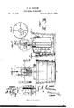
- Figure 1 is a side view of my improved freezer.
- Fig. 2 is a vertical section of the same, taken through the line as m, Fig. 1.
- Fig. 3 is a detail cross-section of the can, taken through the line 3 y, Fig. 2.
- Fig. 4 is a detail section, showing the connection of frame and uprights.
- Fig. 5 is a detail view of a set of buckets.
- the object of this invention is to furnish an improved ice-cream freezer, which will enable ice-cream of any desired number of difierent flavors to be kept distinct and separate while being frozen, and which shall be simple in construction, convenient in use, and effective in operation, freezing the creamquickly, doing its work with a much less outlay of labor, ice, and salt than ordinary freezers.
- the invention consists in the ring-can, provided with the radial partitions, and with the cross-bars or spider for connecting it with the driving-shaft; in the cover provided with the funnel-tube, the cross-bar, and the lugs, in combination with the ring-can, and with the keepers attached to said can; in the combina-f; tion of the sliding frame, the sliding gears wheel, and the rack with the shafts, and with the uprights of the frame-work; and in thev combination fthe buckets with the compartments of the ring-can, as hereinafter fully described.
- A is the tub, in the center of the bottom of which is secured a step, a to receive the lower end of the shaft B.
- an arched or bridge bar To the bottom of the tub A is attached an arched or bridge bar, o through a hole in the center of which the shaft B passes, and upon the upper side of which rests a collar, 1), formed upon the said shaft B.
- G is a ring-can, the outerwall of which is made enough smaller than the tub A, to allow sufficient space for the ice, and the inner wall of which is made of such a diameter as to furnish space for ice around the shaft B.
- the interior or ring space of the can 0 is divided into four, more or less, compartments by radial partitions 0 D are buckets, pans, or cups, which are made of such a shape as to fit into the compartments of the can 0, and of a size depending upon the number'of buckets to be used ineach compartment.
- the buckets D are provided with covers d, and with lugs 01 upon their ends, to serve as handles in handling them, and to receive the arms of the loop or bail E, by means of which they are lowered into and raised out of the compartments of the can 0.
- the arms of the bails E have hooks formed upon their ends to hook upon the lugs 01 of the lower bucket D.
- the bars or spider 0 rest upon the collar 11 of the shaft B, and thus support the can 0.
- a cross-bar, f which has a square hole formed through its center to receive the shaft B.
- the cover F is provided with a tube, f the lower end of which fits into the central cavity of the can 0, and its upper end projects and is made flaring, to serve as a funnel for convenience in introducing the ice and salt into the central cavity of the can C.
- the upper end of the shaft B enters a square hole formed in the lower end of the short vertical shaft G, which revolves in bearings attached to the frame P, that slides up and down upon the uprights H, and has a bevel-gear wheel, I, attached to its upper end.
- a bevel-gear wheel, I attached to its upper end.
- the cover F provided with the funneltube f, the cross-bar f and the lugs f, in combination with the ring-can G, and with the keepers'cflattached to said can, substantially as herein shown and described.
Landscapes
- Engineering & Computer Science (AREA)
- Manufacturing & Machinery (AREA)
- Life Sciences & Earth Sciences (AREA)
- Chemical & Material Sciences (AREA)
- Food Science & Technology (AREA)
- Polymers & Plastics (AREA)
- Operating, Guiding And Securing Of Roll- Type Closing Members (AREA)
Description
S. M. GOSSON.
ICE-CREAM FREEZER.
Patented Jan. 4-, 1876.
IJ/H
N. PETERS, PHOTO-LITHOGRAPHER, WASHINGTON, D10.
, mvsurom momma UNITED STATES PATENT QFF'ICE.
.SYLVAIN M. eosson, OF WHISTLER, ALABAMA.
IMPROVEMENT IN ICE-CREAM FREEZERS;
Specification forming part of Letters Patent No: 171,663, dated January i, 1876; application filed September 11, 1875.
To all whom it may concern:
Be it known that I, SYLVAIN M. Gos- SON, of Whistler, in the county of Mobile and State of Alabama, have invented a new and useful Improvement in Ice-Cream Freezer,
of which the following is a specification:
Figure 1 is a side view of my improved freezer. Fig. 2 is a vertical section of the same, taken through the line as m, Fig. 1. Fig. 3 is a detail cross-section of the can, taken through the line 3 y, Fig. 2. Fig. 4 is a detail section, showing the connection of frame and uprights. Fig. 5 is a detail view of a set of buckets.
Similar letters of reference indicate corresponding parts.
The object of this invention is to furnish an improved ice-cream freezer, which will enable ice-cream of any desired number of difierent flavors to be kept distinct and separate while being frozen, and which shall be simple in construction, convenient in use, and effective in operation, freezing the creamquickly, doing its work with a much less outlay of labor, ice, and salt than ordinary freezers.
The invention consists in the ring-can, provided with the radial partitions, and with the cross-bars or spider for connecting it with the driving-shaft; in the cover provided with the funnel-tube, the cross-bar, and the lugs, in combination with the ring-can, and with the keepers attached to said can; in the combina-f; tion of the sliding frame, the sliding gears wheel, and the rack with the shafts, and with the uprights of the frame-work; and in thev combination fthe buckets with the compartments of the ring-can, as hereinafter fully described. I
A is the tub, in the center of the bottom of which is secured a step, a to receive the lower end of the shaft B. To the bottom of the tub A is attached an arched or bridge bar, o through a hole in the center of which the shaft B passes, and upon the upper side of which rests a collar, 1), formed upon the said shaft B. G is a ring-can, the outerwall of which is made enough smaller than the tub A, to allow sufficient space for the ice, and the inner wall of which is made of such a diameter as to furnish space for ice around the shaft B. The interior or ring space of the can 0 is divided into four, more or less, compartments by radial partitions 0 D are buckets, pans, or cups, which are made of such a shape as to fit into the compartments of the can 0, and of a size depending upon the number'of buckets to be used ineach compartment. The buckets D are provided with covers d, and with lugs 01 upon their ends, to serve as handles in handling them, and to receive the arms of the loop or bail E, by means of which they are lowered into and raised out of the compartments of the can 0. The arms of the bails E have hooks formed upon their ends to hook upon the lugs 01 of the lower bucket D. To the bottom of the can 0 are attached two bars, 0 which cross the lower end of the central cavity of the can O, and'have a square hole formed through their center to receive the shaft B, so that the can may be revolved by the revolution of the said shaft B. The bars or spider 0 rest upon the collar 11 of the shaft B, and thus support the can 0. To the cover F of the can 0 is attached a cross-bar, f which has a square hole formed through its center to receive the shaft B. The cover F is provided with a tube, f the lower end of which fits into the central cavity of the can 0, and its upper end projects and is made flaring, to serve as a funnel for convenience in introducing the ice and salt into the central cavity of the can C. To the cover F are attached lugs f which project downward to enter keepers 0 attached to the opposite sides of the upper part of the can 0, to prevent the said cover and can from turning upon each other. The upper end of the shaft B enters a square hole formed in the lower end of the short vertical shaft G, which revolves in bearings attached to the frame P, that slides up and down upon the uprights H, and has a bevel-gear wheel, I, attached to its upper end. Into the teeth of the gear-wheel I mesh the teeth of a bevelgear wheel, J, attached to a horizontal shaft,
K, which revolves in bearings attached to the sliding frame P, and to one or both the ends of which is attached a crank, L. To the horizontal shaft K is attached one or two balancewheels, M, according to the size of the apparatus. Upon the shaft K is placed a gear wheel, N, which is connected with it by a 2 r 11mins tongue and groove,so that -the said wheelmaybe carried around by and with said shaft, but may be slidlongitudinallyupou it, to throw the said gear-wheel into and out of gear with the toothed bar 0, attached to one of the uprights H, so that by throwingthe wheel N into gear with the rack O and turning the shaft K, the frame 1? and the gearing may be raised away from the shaft B. As the frame P rises its'top cross-bar strikes against and catches upon a spring-catch, Q, attached to the cross-bar 71/, that connects the upper ends of the uprights H. The lower ends of the uprights H are attachedto the middle parts of the side bars of the frame R, which is hinged at one end to the ear of the tub A, and the other end of which catches,
j when shut down, upon a spring-catch, S, at-
tachedoto the other ear of said tub.
Having thus described my invention, I claim as new and desire to secure by Letters Patcut- 1. The ring-can 0, provided with the radial partition 0, and with the crossbars, or spider o for connecting it with its shaft B, substantially as herein shown and described.
2. The cover F, provided with the funneltube f, the cross-bar f and the lugs f, in combination with the ring-can G, and with the keepers'cflattached to said can, substantially as herein shown and described.
The combination of the sliding frame P, the sliding gear-wheel N, and the rack O with the shafts G K and the uprights H of the frame-Work R H 11/, substantially as herein shown and describe 4. The combination of the buckets D with the compartments of the ring-can O, substantially as herein shown and described.
SYLVAIN M. Gosso'N,
Witnesses:
B. F. CARVER, 1 E. W. NIX.
Publications (1)
| Publication Number | Publication Date |
|---|---|
| US171663A true US171663A (en) | 1876-01-04 |
Family
ID=2241070
Family Applications (1)
| Application Number | Title | Priority Date | Filing Date |
|---|---|---|---|
| US171663D Expired - Lifetime US171663A (en) | Improvement in ice-cream freezers |
Country Status (1)
| Country | Link |
|---|---|
| US (1) | US171663A (en) |
-
0
- US US171663D patent/US171663A/en not_active Expired - Lifetime
Similar Documents
| Publication | Publication Date | Title |
|---|---|---|
| US171663A (en) | Improvement in ice-cream freezers | |
| US194145A (en) | Improvement in churns | |
| US217130A (en) | Improvement in ice-cream freezers | |
| US181055A (en) | Improvement in ice-cream freezers | |
| US36904A (en) | Improved ice-cream freezer | |
| US140280A (en) | Improvement in reciprocating churns | |
| US5821A (en) | Cream-freezer | |
| US608446A (en) | Sugar-crystallizer | |
| US281973A (en) | Geoege f | |
| USRE226E (en) | Improvement in cream-freezers | |
| US1030356A (en) | Combined churn and butter-worker. | |
| US323732A (en) | Albeet l | |
| US40370A (en) | Improved machine for making dough, paste | |
| US1196906A (en) | Combined churn and butter-worker. | |
| US267483A (en) | Post-auger | |
| US151887A (en) | Improvement in churns | |
| US146025A (en) | Improvement in malt-driers | |
| US158097A (en) | Improvement in butter-workers | |
| US413137A (en) | And michael a | |
| US180937A (en) | Improvement in bottle-washers | |
| US209700A (en) | Improvement in liquid-freezers | |
| US144762A (en) | Improvement in spool-cases | |
| US391125A (en) | Migny | |
| US790817A (en) | Bottle-washing apparatus. | |
| US154307A (en) | Improvement in show-cases and sample-boxes |