US171615A - Improvement in petroleum-wells - Google Patents
Improvement in petroleum-wells Download PDFInfo
- Publication number
- US171615A US171615A US171615DA US171615A US 171615 A US171615 A US 171615A US 171615D A US171615D A US 171615DA US 171615 A US171615 A US 171615A
- Authority
- US
- United States
- Prior art keywords
- tube
- packer
- well
- steam
- water
- Prior art date
- Legal status (The legal status is an assumption and is not a legal conclusion. Google has not performed a legal analysis and makes no representation as to the accuracy of the status listed.)
- Expired - Lifetime
Links
Images

Classifications
-
- E—FIXED CONSTRUCTIONS
- E21—EARTH OR ROCK DRILLING; MINING
- E21B—EARTH OR ROCK DRILLING; OBTAINING OIL, GAS, WATER, SOLUBLE OR MELTABLE MATERIALS OR A SLURRY OF MINERALS FROM WELLS
- E21B36/00—Heating, cooling or insulating arrangements for boreholes or wells, e.g. for use in permafrost zones
Definitions
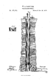
- Figure 1 is a vertical section of a petroleumwell having my improvement applied thereto, and Fig. 2 is a detached view of the steampipe guiding-flange.
- This invention is designed to reduce the cost which is involved in the application of such tubes.
- A represents the oil-bearing rock, and A A A the upper strata of rock and soil.
- B is the casing,which usually extends to such depth as will exclude the fresh water.
- B is the casingcap.
- 0 is the pumping-tube, of any usual or approved construction, and provided with the ordinary pumping-rod and valves, which need not, therefore, be described.
- D is the steaur tube, extending to near the bottom of the well, care being taken to keep its lower end above such portion of dead-oil or water as cannot be readily removed by the pump.
- E is the supplementary or protecting tube, surrounding the steam-tube D, and either united to the packer F by a water-tight joint, or connected with the steam-tube D by a watertight joint near the packer, or extending through the packer, as shown in the drawings.
- the packer (represented at F) may be of any desired manufacture, and as this invention does not relate to the packer, I propose to employ any one which will answer my purpose.
- Tube E is rigidly attached to the guide 0, so that it (tube E) may be raised and lowered with the pumpingtube, and the distance at which these tubes 0 and E are placed apart may be governed by the kind of packer, if any, which is to be used with them, or by any other circumstance. or feature of construction.
- the guiding-flange is, by preference, about one-quarter of an inch less in diameter than the bore of the well.
- the steain-tubeD may be introduced, and when it reaches the guiding-flange G the converging sides of the flange will insure that the lower end of .the steam-pipe enters the tube E without fail.
- the dead-oil or oil and water are pumped out through the pumping-tube 0, in order that the discharge of steam may be unobstructed, as a small amountof either oil or water in the well will prevent heat thereby produced will beconfinedbelow' the packer, as -the. water above said packer.
- i i I a suflicient quantity to-produce the desired result may bepoured in from above.
- flange 0 s01 jmnch smaller than the bore of the well is to it permit water to be poured into the well to snr round tube E without having such water ru into. the tube.
- the steam-tube may be withdrawn without disturbing the packer.
Landscapes
- Life Sciences & Earth Sciences (AREA)
- Engineering & Computer Science (AREA)
- Geology (AREA)
- Mining & Mineral Resources (AREA)
- Physics & Mathematics (AREA)
- Environmental & Geological Engineering (AREA)
- Fluid Mechanics (AREA)
- General Life Sciences & Earth Sciences (AREA)
- Geochemistry & Mineralogy (AREA)
- Production Of Liquid Hydrocarbon Mixture For Refining Petroleum (AREA)
Description
..U lllllllllll Patented. 1m. 2s, 1a75.'
max/4 1M141 WALLACE L. HARDISON, OF ST.
' UNITED fS'IATESf PATENT [OFEIGE PETERSBURG, PENNSYLVANIA.
IMPROVEMENT IN PETROLEUM-WELLS.
Specification forming part of Letters Patent No. 17 [,615, dated December 28, 1875; application filed,
Novemberl9,1875. f I
marked thereon, which form a part of this specification.
Figure 1 is a vertical section of a petroleumwell having my improvement applied thereto, and Fig. 2 is a detached view of the steampipe guiding-flange.
In another application for a patent for improvements in oil-wells, of even date herewith,
I have shown and described tubes for protect ing the steam-tube from contact with the saltwater which is frequently found in such wells, I
and for permitting the escape of the gas and the surplus steam from the well without the injury to the well which would ordinarily result from the action of the heat and moisture of the escaping steam upon the slate rock of the well. This invention is designed to reduce the cost which is involved in the application of such tubes. I
A represents the oil-bearing rock, and A A A the upper strata of rock and soil. B is the casing,which usually extends to such depth as will exclude the fresh water. B is the casingcap. 0 is the pumping-tube, of any usual or approved construction, and provided with the ordinary pumping-rod and valves, which need not, therefore, be described. D is the steaur tube, extending to near the bottom of the well, care being taken to keep its lower end above such portion of dead-oil or water as cannot be readily removed by the pump. E is the supplementary or protecting tube, surrounding the steam-tube D, and either united to the packer F by a water-tight joint, or connected with the steam-tube D by a watertight joint near the packer, or extending through the packer, as shown in the drawings.
The packer (represented at F) may be of any desired manufacture, and as this invention does not relate to the packer, I propose to employ any one which will answer my purpose.
As the salt -water will rarely rise to within some hundreds of feet of the top of the well, I have invented a construction which enables me to dispense with such length of pipe as would otherwise be required to reach from'the salt-water level to the top of the well. This salt-water level can be easily ascertained by proper soundings, and at this level, or at a short distance above this point, I attach a steam-tube guiding-flange, G, to the pumping-tube O. The flange need not be rigidly connected to the pumping-tube; in fact, l usually secure a collar or clamp to the pumpingtube below the flange, so that when the tube is withdrawn from the well the collar will bring the flange with it. It is provided with two holes-one, c, for the pumping-tube, and another, 0, for the protecting-tube E. It is circular in form, and is dishing or concave, with its sides converging toward the protecting-pipe opening 0. Tube E is rigidly attached to the guide 0, so that it (tube E) may be raised and lowered with the pumpingtube, and the distance at which these tubes 0 and E are placed apart may be governed by the kind of packer, if any, which is to be used with them, or by any other circumstance. or feature of construction. The guiding-flange is, by preference, about one-quarter of an inch less in diameter than the bore of the well.
After the pumping-tube G and protectingtube E, with packer F, have been placed in position, the steain-tubeD may be introduced, and when it reaches the guiding-flange G the converging sides of the flange will insure that the lower end of .the steam-pipe enters the tube E without fail.
In operating my devices, the dead-oil or oil and water are pumped out through the pumping-tube 0, in order that the discharge of steam may be unobstructed, as a small amountof either oil or water in the well will prevent heat thereby produced will beconfinedbelow' the packer, as -the. water above said packer.
will condense the steam which might otherwise pass up throughtube E, and. in. case. there be not enough water above the packer, i i I a suflicient quantity to-produce the desired result may bepoured in from above.
One of the objects in making. flange 0 s01 jmnch smaller than the bore of the well is to it permit water to be poured into the well to snr round tube E without having such water ru into. the tube.
By my construction the steam-tube may be withdrawn without disturbing the packer.
What I claim is- 1. The combination of the pumpingktnjbejlO thestealn-tubeD, and the "protecting-tube E, i supported upon the pumping-tube, substan tially as set forth.
set forth. I
In testimonythat I claim the foregoingas my own I affix my-signature in presence of two i witnesses.
'WALLAOE L. HARDISON. Witnesses: 1 E. 0. WEAVER,
H. H. DOUBLEDAY.
2. The combinationof thegnidingflanQdO! with the protecting-tube E; snbstantially as];
Publications (1)
| Publication Number | Publication Date |
|---|---|
| US171615A true US171615A (en) | 1875-12-28 |
Family
ID=2241022
Family Applications (1)
| Application Number | Title | Priority Date | Filing Date |
|---|---|---|---|
| US171615D Expired - Lifetime US171615A (en) | Improvement in petroleum-wells |
Country Status (1)
| Country | Link |
|---|---|
| US (1) | US171615A (en) |
Cited By (1)
| Publication number | Priority date | Publication date | Assignee | Title |
|---|---|---|---|---|
| US3340932A (en) * | 1965-04-21 | 1967-09-12 | Armco Steel Corp | Sub-surface connector for plural tubing elements |
-
0
- US US171615D patent/US171615A/en not_active Expired - Lifetime
Cited By (1)
| Publication number | Priority date | Publication date | Assignee | Title |
|---|---|---|---|---|
| US3340932A (en) * | 1965-04-21 | 1967-09-12 | Armco Steel Corp | Sub-surface connector for plural tubing elements |
Similar Documents
| Publication | Publication Date | Title |
|---|---|---|
| US326439A (en) | Protecting wells | |
| US1014272A (en) | Wall-packer for oil-wells. | |
| US171563A (en) | Improvement in petroleum-wells | |
| US997191A (en) | Well-casing. | |
| US260803A (en) | Artesian vacuum-well | |
| US484764A (en) | Apparatus for boring artesian wells | |
| US208619A (en) | Improvement in well-tubing | |
| US400466A (en) | Well-boring apparatus | |
| US306799A (en) | William d | |
| US403183A (en) | Apparatus for removing gummy matter from oil-wells | |
| US208610A (en) | Improvement in casings for oil-wells | |
| US399747A (en) | Joseph edwards | |
| US216064A (en) | Improvement in regulating the flow of oil-wells | |
| US436216A (en) | Device for operating oil-wells | |
| US260401A (en) | Ambeose n | |
| US166357A (en) | Improvement in fire-plugs | |
| US2290431A (en) | Extraction of fluids from the earth | |
| US320176A (en) | Pump for oil-wells | |
| US154096A (en) | Improvement in oil-rock preservers | |
| US129314A (en) | Improvement in wells | |
| US203044A (en) | Improvement in oil-well packings | |
| US1149751A (en) | Packer for oil-wells. | |
| US685522A (en) | Packing for drift, gallery, or other openings in mines. | |
| US485953A (en) | Siphonic water-distributing apparatus | |
| US147780A (en) | Improvement in submarine sand-elevators |