US1715744A - Automatic-stop elevator system - Google Patents
Automatic-stop elevator system Download PDFInfo
- Publication number
- US1715744A US1715744A US205570A US20557027A US1715744A US 1715744 A US1715744 A US 1715744A US 205570 A US205570 A US 205570A US 20557027 A US20557027 A US 20557027A US 1715744 A US1715744 A US 1715744A
- Authority
- US
- United States
- Prior art keywords
- car
- relay
- floor
- coil
- conductor
- Prior art date
- Legal status (The legal status is an assumption and is not a legal conclusion. Google has not performed a legal analysis and makes no representation as to the accuracy of the status listed.)
- Expired - Lifetime
Links
Images

Classifications
-
- B—PERFORMING OPERATIONS; TRANSPORTING
- B66—HOISTING; LIFTING; HAULING
- B66B—ELEVATORS; ESCALATORS OR MOVING WALKWAYS
- B66B1/00—Control systems of elevators in general
- B66B1/02—Control systems without regulation, i.e. without retroactive action
- B66B1/06—Control systems without regulation, i.e. without retroactive action electric
- B66B1/08—Control systems without regulation, i.e. without retroactive action electric with devices, e.g. handles or levers, in the cars or cages for direct control of movements
Definitions
- My invention relates to control systems and it has particular relation to control systems for elevators, hoists and similar appa" ratus.
- One object of my invention is to provide a control system for machines operable over predeterminedpaths wherein the machines may be selectively stopped at any one of a plurality of points along the paths.
- Another object of my invention is to provide a control system for elevators oi the type wherein the elevator is started by an attendant on the elevator and is-automati eally stopped in response to the operation of passenger-actuated push-buttons, either from within the car or at the several landings traversed bythe elevat'or.
- Another object of my invention is to provide a control system for elevators of'the type designated in the preceding paragraph wherein a plurality of cars in a bank are so controlled that the first car to approach a floor at which a passenger-actuated means has been operated will be stopped at that floor only when travelling in the direction corresponding to the passenger-actuated device operated.
- Another object of my invention is to provide a control system for elevators wherein the car is started by an attendant on the car and is automatically stopped in response to passenger-actuated devices, and wherein no mechanical interconnection between the elevator and the hatchway is required to effect such stops.
- Another object of my invention is to provide a suitable relay structure for accomplishing the result of stopping the car without mechanical connections between the car and the hatchway.
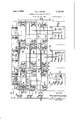
- Figure 1 is a diagrammatic view of one form ofmy invention asapplied to three elevators operating to serve five floors;
- Fig. 2 is a View, in side elevation, of a I relay for use with the sytem shown in Fig.
- Fig. 3 is a plan view of the relay shown in Fig.2.
- the system'therein sho'wncomprises a plurality of elevator cars A, B and C, which are controlled through A CORPORATION OF PENNSYL- HEISSUE the agency of car switches ACS, BCS and CCS, which, in turn, respectively govern the up-anddown direction-switches, A1, A2, B1, B2, and C1, C2.
- the elevator cars are illustrated as operating in hatchways defined by the broken lines A, B and C, respectively, .which hatchways traverse five floors designated as 1st, 2nd, 3rd, 1th and 5th.
- Push-buttons all, 41), 3U, 8D, 2U, and 21) are arranged respectively at the 4th, 8rd and 2nd floors for actuation by persons desiring to use the elevators.
- Each of the elevator cars A, B and C is provided with a series of push-buttons, one for each of the floors, designated respectively as A4, A3, A2, etc. It will be noted in this figure that only a single button for each of the floors is provided on the car, and, as will be hereinafter explained, these buttons may be operated to stop the associated elevator car when travelling in either direction.
- Inductor relays A100, A101 and A102 are illustrated as associated with the corresponding doWn-ioor buttons 4D, 3D and 2D.
- a similar series of relays A104, A105 and A106 are associated with the buttons 4U, 3U and 2U.
- Similar inductor relays are associated with the cars 13 and C designated by like reference numerals preceded by the characters B and C, respectively.
- Each of the relays A100, A101. etc, is provided with two energizing coils designated as 107 and 108, respectively, and a hold-back coil 109. Fteferrin to Figs. 2 and 3',the structure of these re ays may be readily determined.
- Each of these relays comprises a suitable base 110 upon which coils 107 and 108 are suitably supported, as by supporting mem bers 113 and 114.
- a pair of armature members 115 and 116 are rigidly mounted upon a core 117 extending through the coils 107 and 108 for unitary rotary movement in the supporting members. 113 and 114.
- Each of the armature members comprises an upright member1l8, and upper 'inturned fastening portion 119 and a lower in-turned pole face 120.
- the member 116 also has a second i turned pole face 121 for a purpose hereinafter described.
- the pole faces 120 and 121 extend parallel to each other in planes at r g t angles to the fastening member 119.
- Rigid 1y connecting the upper inturned members 119 of both of the armature members contacting engagement with a 115 and 116 is a bar 122 formed of suitable insulating material upon which may be mounted suitable contact members 123 and 1 preferably formed of resilient material so arranged that, upon movement of the con-' tact members 123 and 124 to'disengage their respectively cooperating contact members 125 and 126, the contact member 126 will.
- t arrangement is to cause disenga ementof contactmembers 123 and125 a s ort time prior to the disengagement of the con members 124 'and126.
- the relay is mounted in the hatchway' adjacent to the path of movement ot'the elevator car, for example, the car A.
- the car A' carries an inductor plate --X so mounted as toapproach closely adjacent to the pole' facel20 of the armature members 115 and 116,.as the elevator car passes the point at which the relay is mounted.
- a suitable hold-back coil 109 is mounted upon the base 110.
- the coi1 109 is This'coil 109 is so design provided with a suitable core 129,'which ex- Y tends closely adjacent to'the in-turned pole --face 121' on' the armature member 116 when the armature member 116 is in the normal or full-line position illustrated -in Fig. 2. ed that the effectproduced by it, when energized, will be to. revent the actuation of the armature memrs 115 and 116 by the inductor plate X,
- the up-di-rection switch A1 operates to energize the drivingmotor (not shown) inany suitable manner, and closes a self-holding circuit which extends -from line conductor L1 through conductor 130,;thecoil of updirection switch A1, conductors 131 and 137,
- the inductor plate X pass the relay A106 and actuate this relay to open its contact members 143 and 149.
- the contact members ,143 are arranged to open justior to-the openingof contact members 149.
- any of the elevator cars A, B and C which arrive adjacent the second floor, traveling in the upward direction, will operate their respective relays A106, B106,--etc. to stop the car at thesecond floor for the passenger who operated the button 2U.
- the corresponding relay A106, B106, etc. would not be operated, by reason of the effect of the hold-back coil associated with such relay.
- the car B will be caused to stop in response to passenger-operated push buttons at the various floors only when the car is traveling in the direction corresponding to that for which such buttons are operated.
- junction-point 169 From junction-point 169, another branch of the circuit extends by way of conductor 178 through the coil 108 of relay A100, conductors 179, 180 and 181, normally-' closed contact members Alb, and conductors 182, 177, and 130 to line conductor L1.
- This branch of the circuit will be opened by the operation of up-direction switch Al as the cal-continues its upward travel, thus permitting only the coil 171 for upinduetor relay A104 to remain energized.
- the inductor iron X will approach the relay A104; and open contact member 139 of the relay A104, thereby (leenergizing the up direction switch A1 and stopping the elevator car A at the 4th floor.
- the same push-button A ton the car may be used to stop the car when traveling either upwardly or downwardly, and the direction of the movement of the car will govern which of these relays is to be effective.
- My invention permits the use of the single ear button, as hereinbefore described, and reduces the number of conductors required in the cable connecting the elevator car to the stationary control devices.
- a car operable past a floor, means for starting said car, call means at said floor, call means on said ear, means for stopping said car at said floor comprising a relay having two actuating coils, means for energizing one of said coils responsive to the actuation of said floor-call means, means for energizing the other of said coils responsive tothe actuation of said car-call means, and means operable in accordance with movements of said car for rendering said relay operable to stop said car.
- a car operable past a floor, means for starting said car, call means at said floor, call means on.
- said car means for stopping said car at said fioorcomprising a relay having two actuating coils, means for energizingone of said coils responsive tothe actuation of said floor-call means, means for energizing the other of said coils responsive to the actuation of said car-call means, means operable in accordance with movements of said car for rendering said relay operable to stop said. car, means for maintaining said call means operative when actuated, and means op- 4? c mew erable' hy actuation of said stopping 'for restoring said call means to inoperative position; y
- a pair of energizable coils on said core nor-' mally effective to actuate said armature when energized means for rendering either of said'coils efiective to actuate said armature when either of them is energized, and mag netic means for preventing actuation of said armature by'said energized coil.
- switches comprising means for retarding the actuation of said switch.
Landscapes
- Engineering & Computer Science (AREA)
- Automation & Control Theory (AREA)
- Elevator Control (AREA)
Description
June 4, 1929. w. F. EAMES AUTOMATIC STOP ELEVATOR SYSTEM Filed July 14, 1927 2 Sheets-Sheet R O T N E V m WiIliq'mEEomes ATTO'RNEY Jqng 4, 1929., w. F. EAMES AUTOMATIC STOP ELEVATOR SYSTEM 2 Shets-Sheet Filed July 14, 1927 NNK INVENTOR Wi liomF Eames AT'TORNEY .latentee carves sraTE-s PATENT OFFICE.
HOUSE ELECTRIC & MANUFACTURING COMPANY,
VANIA'.
AUTOMATIC-STOP ELEVATOR SYSTEM.
Application filed ihily 14, 1927. Serial No. 205,570.
My invention relates to control systems and it has particular relation to control systems for elevators, hoists and similar appa" ratus.
One object of my invention is to provide a control system for machines operable over predeterminedpaths wherein the machines may be selectively stopped at any one of a plurality of points along the paths.
Another object of my invention is to provide a control system for elevators oi the type wherein the elevator is started by an attendant on the elevator and is-automati eally stopped in response to the operation of passenger-actuated push-buttons, either from within the car or at the several landings traversed bythe elevat'or. I
Another object of my invention is to provide a control system for elevators of'the type designated in the preceding paragraph wherein a plurality of cars in a bank are so controlled that the first car to approach a floor at which a passenger-actuated means has been operated will be stopped at that floor only when travelling in the direction corresponding to the passenger-actuated device operated.
Another object of my invention is to provide a control system for elevators wherein the car is started by an attendant on the car and is automatically stopped in response to passenger-actuated devices, and wherein no mechanical interconnection between the elevator and the hatchway is required to effect such stops.
Another object of my invention is to provide a suitable relay structure for accomplishing the result of stopping the car without mechanical connections between the car and the hatchway.
My device will be described with reference to the accompanying drawings, wherein Figure 1 is a diagrammatic view of one form ofmy invention asapplied to three elevators operating to serve five floors;
Fig. 2 is a View, in side elevation, of a I relay for use with the sytem shown in Fig.
1; and
Fig. 3 is a plan view of the relay shown in Fig.2.
Referring to Fig. 1, the system'therein sho'wncomprises a plurality of elevator cars A, B and C, which are controlled through A CORPORATION OF PENNSYL- HEISSUE the agency of car switches ACS, BCS and CCS, which, in turn, respectively govern the up-anddown direction-switches, A1, A2, B1, B2, and C1, C2.
The elevator cars are illustrated as operating in hatchways defined by the broken lines A, B and C, respectively, .which hatchways traverse five floors designated as 1st, 2nd, 3rd, 1th and 5th. Push-buttons all, 41), 3U, 8D, 2U, and 21) are arranged respectively at the 4th, 8rd and 2nd floors for actuation by persons desiring to use the elevators.
Each of the elevator cars A, B and C is provided with a series of push-buttons, one for each of the floors, designated respectively as A4, A3, A2, etc. It will be noted in this figure that only a single button for each of the floors is provided on the car, and, as will be hereinafter explained, these buttons may be operated to stop the associated elevator car when travelling in either direction.
Inductor relays A100, A101 and A102 are illustrated as associated with the corresponding doWn-ioor buttons 4D, 3D and 2D. A similar series of relays A104, A105 and A106 are associated with the buttons 4U, 3U and 2U. Similar inductor relays are associated with the cars 13 and C designated by like reference numerals preceded by the characters B and C, respectively.
Each of the relays A100, A101. etc, is provided with two energizing coils designated as 107 and 108, respectively, and a hold-back coil 109. Fteferrin to Figs. 2 and 3',the structure of these re ays may be readily determined.
Each of these relays comprises a suitable base 110 upon which coils 107 and 108 are suitably supported, as by supporting mem bers 113 and 114. A pair of armature members 115 and 116 are rigidly mounted upon a core 117 extending through the coils 107 and 108 for unitary rotary movement in the supporting members. 113 and 114. Each of the armature members comprises an upright member1l8, and upper 'inturned fastening portion 119 and a lower in-turned pole face 120. The member 116 also has a second i turned pole face 121 for a purpose hereinafter described. The pole faces 120 and 121 extend parallel to each other in planes at r g t angles to the fastening member 119.
Rigid 1y connecting the upper inturned members 119 of both of the armature members contacting engagement with a 115 and 116 is a bar 122 formed of suitable insulating material upon which may be mounted suitable contact members 123 and 1 preferably formed of resilient material so arranged that, upon movement of the con-' tact members 123 and 124 to'disengage their respectively cooperating contact members 125 and 126, the contact member 126 will.
follow'throu'gh for a short distance, bein limited b bracing member 127. The function of t arrangement is to cause disenga ementof contactmembers 123 and125 a s ort time prior to the disengagement of the con members 124 'and126. In the preferred operation of my relay illustrated in Figs. 2 and 3, the relay is mounted in the hatchway' adjacent to the path of movement ot'the elevator car, for example, the car A.
The car A'carries an inductor plate --X so mounted as toapproach closely adjacent to the pole' facel20 of the armature members 115 and 116,.as the elevator car passes the point at which the relay is mounted.
Should either of the coils 107 and 108 be energized at the time the inductor plate Xi passes-the pole face 120, the magnetic force produced by the energized coil will cause the armature members 115- and 116'to assume a position indicated by the dot and dash lines in Fig. 2. This movement of the armature members will cause disengagement of thecontact members 123,125 and 124, 126'.
For a purpose described, it is desirable to prevent the actuation ofthe. armature members 115 and 116,
under certain conditions, and, to provide 'for this effect, a suitable hold-back coil 109 is mounted upon the base 110. The coi1 109 is This'coil 109 is so design provided with a suitable core 129,'which ex- Y tends closely adjacent to'the in-turned pole --face 121' on' the armature member 116 when the armature member 116 is in the normal or full-line position illustrated -in Fig. 2. ed that the effectproduced by it, when energized, will be to. revent the actuation of the armature memrs 115 and 116 by the inductor plate X,
even thcughgthe coil 107 or thecoil-108 isenergized.
'Referrmg. again to Fig. 1, the system bestbe understood with reference to an assumed operation. Asuming the. elevator car A tobe at the first floor, the attendant on the'car may actuate the handle of the car switch ACS the left, thus energizing the I Iconductor which will be hereinafter" fup-direction switch A1 by a circuit which 1 extends from line conductor L1 throughconductors' 130, the coilof up-direction switch A1, conductor 131-, contact members 132, 133 and 134 of thecar switch AGS, and conjductors 135 and 136 toline conductor L2.
The up-di-rection switch A1 operates to energize the drivingmotor (not shown) inany suitable manner, and closes a self-holding circuit which extends -from line conductor L1 through conductor 130,;thecoil of updirection switch A1, conductors 131 and 137,
the contact ,members A10, conductor 138,
normally-closed contact members 139' of the I inductor relay iA104,"-conductor "140, nor mally-closed'contact members 141 of inductor relay A105, conductor 142, normally: closed contact members 143 of inductor relay A106 and conductors .144 and 136 to line conductor L2. The attendant on car- A: may
atany time thereafter, center the car switch 7 ACS without interrupting the upward mov'ement of the.;elevator car A..
Assume, for example, that a person at the second floor-desires to travel upwardly and operates the button 2U at that floor, This to I operation willcomplete'a circuit to energize the .c0il.145 of the up-inductor-relay A106 for thesecond floor. This circuit extends" from line conductor 'Ll through conductor 146, the push-button 2U, hold-down coil 147', conductor. 148, the normally-closed contact members 149 of theiinductor relay A106,
,155 through conductor 156, the coil 145 of relay A106 and conductors 157 and 136- to line conductor The parallel circuits' for the relays B106 0106 may readily be seen and-will not, therefore, be traced. As the car A approaches the second floor,
the inductor plate X pass the relay A106 and actuate this relay to open its contact members 143 and 149. 'As described with reference to Figs. 2 and 3, the contact members ,143 are arranged to open justior to-the openingof contact members 149.
r "Hhe opening of contact members 143 opens the hold-circ'uit-for the up-di'r'ection switch A1, and the car stops at the second 'floor.
The opening of contact members 149-opens the circuit ,for the coil 145 for the relay A106 and 'for the corresponding coils onthe relays B106 and 0106, thus restoringall of these relays tof'thei'r normal dee'nergizedcondition. l
The attendant on car A opens the door,
ment of the car switch ACS.
As may be readily observed from the foregoing description, any of the elevator cars A, B and C which arrive adjacent the second floor, traveling in the upward direction, will operate their respective relays A106, B106,--etc. to stop the car at thesecond floor for the passenger who operated the button 2U. However, should oneof the elevator cars A, B, and 0 pass the second floor traveling downward, the corresponding relay A106, B106, etc. would not be operated, by reason of the effect of the hold-back coil associated with such relay.
Assuming, for example, that the elevator car B approaches the second floor, traveling downward, prior to the arrival of car A at the second floor, traveling upward, the inductor iron X on the car B will approach closely adjacent to the energized relay B106, but the hold-back coil 158 will prevent this relay B106 from operating, as explained below. 7
When the elevator ear B is traveling downward, the circuit for the hold-back coils through each of the hold- back coils 160, 159
and 158, and conductor 136 to line conductor L2. In this manner, the car B will be caused to stop in response to passenger-operated push buttons at the various floors only when the car is traveling in the direction corresponding to that for which such buttons are operated.
Assuming now that the passenger entering the car A at the second floor desires to travel to the 4th floor and so informs the attendant on the car A, the attendant presses the 4th floor button A4 on the car, thus completing a circuit which extends from line conductor L2, through conductors 136, 135 and 166, the push-button A l, hold-down coil 167 for the button A 1, and conductor 168 to junctionpoint 169, whence one branch of the circuit extends, by way of conductor 170, through the coil 171 of the relay A10 1, conductors 172, 173, 174 and 175, contact members A2?) on the down-direction switch A2 and conductors 176, 177 and 130 to line conductor L1. From junction-point 169, another branch of the circuit extends by way of conductor 178 through the coil 108 of relay A100, conductors 179, 180 and 181, normally-' closed contact members Alb, and conductors 182, 177, and 130 to line conductor L1. This branch of the circuit, however, will be opened by the operation of up-direction switch Al as the cal-continues its upward travel, thus permitting only the coil 171 for upinduetor relay A104 to remain energized.
As the car approaches the 1th floor, the inductor iron X will approach the relay A104; and open contact member 139 of the relay A104, thereby (leenergizing the up direction switch A1 and stopping the elevator car A at the 4th floor. As may readily be seen from the description of the circuits for the coil 171 of relay A104 and the coil 108 of the relay A100, the same push-button A ton the car may be used to stop the car when traveling either upwardly or downwardly, and the direction of the movement of the car will govern which of these relays is to be effective. My invention permits the use of the single ear button, as hereinbefore described, and reduces the number of conductors required in the cable connecting the elevator car to the stationary control devices. Moreover, the use of the relay of the type shown in Figs. 2 and 3 permits a compact I I assembly of the apparatus used for each stop, yet also permits ready interconnection of several elevator cars in a bank to be made for operation from a common control means at the floors.
The apparatus disclosed is merely illustrative and may be changed in any suitable manner without modifying essentials of my invention. I do not, therefore, desire to be limited to the details shown and describedexcept as defined in the appended claims.
I claim as my invention: 7
1. In a control system for elevators, a car operable past a floor, means for starting said car, call means at said floor, call means on said ear, means for stopping said car at said floor comprising a relay having two actuating coils, means for energizing one of said coils responsive to the actuation of said floor-call means, means for energizing the other of said coils responsive tothe actuation of said car-call means, and means operable in accordance with movements of said car for rendering said relay operable to stop said car.
2. In a control system for elevators, a car operable past a floor, means for starting said car, call means at said floor, call means on.
said car, means for stopping said car at said fioorcomprising a relay having two actuating coils, means for energizingone of said coils responsive tothe actuation of said floor-call means, means for energizing the other of said coils responsive to the actuation of said car-call means, means operable in accordance with movements of said car for rendering said relay operable to stop said. car, means for maintaining said call means operative when actuated, and means op- 4? c mew erable' hy actuation of said stopping 'for restoring said call means to inoperative position; y
" 3. If a relay for elevatorcontrol systems,
'5' a core, an armature mounted on said core,
' .a pan of energizable coils on said core normally effective to. actuate said armature when energized, and means for rendering either ,of said coils efiectlve to actuate sa1 armature when either of them is energized.
4. In a relay for elevator-control systems, a core, an armature mounted on sand core,
. a pair of energizable coils on said core nor-' mally effective to actuate said armature when energized, means for rendering either of said'coils efiective to actuate said armature when either of them is energized, and mag netic means for preventing actuation of said armature by'said energized coil.
5, In a relay system for elevators, a relay,
a coil therefor, means for energizing said coil, means for maintaining saidcoil active when energized, and means operably responsive to the operation of relay for deenergizing said coil. 7
6. In a relay system for elevator control,
'said switches comprising means for retarding the actuation of said switch.
In testimony whereof, I'have hereunto a relay comprising a coil, an armature and suliscribed my name this 7th day of July,
mm n. ES.
Priority Applications (1)
| Application Number | Priority Date | Filing Date | Title |
|---|---|---|---|
| US205570A US1715744A (en) | 1927-07-14 | 1927-07-14 | Automatic-stop elevator system |
Applications Claiming Priority (1)
| Application Number | Priority Date | Filing Date | Title |
|---|---|---|---|
| US205570A US1715744A (en) | 1927-07-14 | 1927-07-14 | Automatic-stop elevator system |
Publications (1)
| Publication Number | Publication Date |
|---|---|
| US1715744A true US1715744A (en) | 1929-06-04 |
Family
ID=22762735
Family Applications (1)
| Application Number | Title | Priority Date | Filing Date |
|---|---|---|---|
| US205570A Expired - Lifetime US1715744A (en) | 1927-07-14 | 1927-07-14 | Automatic-stop elevator system |
Country Status (1)
| Country | Link |
|---|---|
| US (1) | US1715744A (en) |
-
1927
- 1927-07-14 US US205570A patent/US1715744A/en not_active Expired - Lifetime
Similar Documents
| Publication | Publication Date | Title |
|---|---|---|
| US3519106A (en) | Pulse-supervised transportation systems | |
| US1715744A (en) | Automatic-stop elevator system | |
| USRE17555E (en) | House electric | |
| US1905228A (en) | Signaling system for elevators | |
| US1844514A (en) | Elevator control system | |
| US2185748A (en) | Elevator system | |
| US1983940A (en) | Collector control system | |
| US2075102A (en) | Electric elevator system | |
| US1827796A (en) | Elevator control system | |
| US2642158A (en) | Selectively zoned elevator system | |
| US2300953A (en) | Interlock circuit for vertical door operators | |
| US1720538A (en) | Elevator-control system | |
| US2997134A (en) | Elevator systems | |
| US1955303A (en) | Elevator system | |
| US2827980A (en) | Elevator systems | |
| US2074575A (en) | Elevator system | |
| US2044152A (en) | Automatic leveling device for elevators | |
| US1763151A (en) | Signaling system | |
| US2338582A (en) | Elevator signaling system | |
| US3036665A (en) | Self service elevator with simplified mechanism | |
| US1640559A (en) | Control system | |
| US1811622A (en) | Signal system for elevators | |
| US1537079A (en) | Elevator system | |
| US1924327A (en) | Elevator control system | |
| US1984308A (en) | Control system |