US1715315A - Skeining reel - Google Patents
Skeining reel Download PDFInfo
- Publication number
- US1715315A US1715315A US201526A US20152627A US1715315A US 1715315 A US1715315 A US 1715315A US 201526 A US201526 A US 201526A US 20152627 A US20152627 A US 20152627A US 1715315 A US1715315 A US 1715315A
- Authority
- US
- United States
- Prior art keywords
- reel
- raceways
- arms
- head
- shaft
- Prior art date
- Legal status (The legal status is an assumption and is not a legal conclusion. Google has not performed a legal analysis and makes no representation as to the accuracy of the status listed.)
- Expired - Lifetime
Links
Images

Classifications
-
- B—PERFORMING OPERATIONS; TRANSPORTING
- B65—CONVEYING; PACKING; STORING; HANDLING THIN OR FILAMENTARY MATERIAL
- B65H—HANDLING THIN OR FILAMENTARY MATERIAL, e.g. SHEETS, WEBS, CABLES
- B65H49/00—Unwinding or paying-out filamentary material; Supporting, storing or transporting packages from which filamentary material is to be withdrawn or paid-out
- B65H49/18—Methods or apparatus in which packages rotate
- B65H49/20—Package-supporting devices
- B65H49/30—Swifts or skein holders
-
- B—PERFORMING OPERATIONS; TRANSPORTING
- B65—CONVEYING; PACKING; STORING; HANDLING THIN OR FILAMENTARY MATERIAL
- B65H—HANDLING THIN OR FILAMENTARY MATERIAL, e.g. SHEETS, WEBS, CABLES
- B65H2701/00—Handled material; Storage means
- B65H2701/30—Handled filamentary material
- B65H2701/31—Textiles threads or artificial strands of filaments
Definitions
- My invention relates to skeining reels and particularly to a collapsible reel for skeining artificial silk and the like.
- the object of my invention is to provide an improved construction by which the reel arms are accurately supported in predetermined position durlng the reeling operation, and readily collapsed for doiiing the wound skein.
- FIG. 1 is a vertical section through a reel in which my invention is embodied in oner form
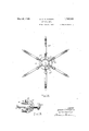
- Fig. 2 is an end elevation thereof
- Fig. 3 is a section through the sliding cone on line 3-3, Fig. 2.
- the reel is supported on an elongated pin or stud 15 secured in fixed position to the frame 16 by means of a nut 17. Between the collar 18 on the stud and the frame 16, is journalled gear 19 which meshes with a gear 2O fast on the spindle of drive pulley 21 controlled by the hand clutch lever 22. The reel hub 23 isfast with the gear 19, to which it is attached by machine screws 24.
- the reel hub is integral with the hollow shaft 25 which has an extended bearing on the stud 15 and is exteriorly notched at 26 for a purpose hereinafter explained. Sliding on the shaft 25 is the reel collapsing cone-head 27 Into the outer end of the latter is screwed the axially pierced knob 28 which slides on the shaft 25.
- the reel arms 29 are severally hinged to the hub 23 by hinge pins 30. Each arm is also supported by an adjustable pin 31 provided with a ball head 32 which engages an undercut and angled raceway 33 formed in the conehead 27.
- the several raceways have reaches ar'parallel with the shaft 25 and reaches y which axially converge toward the outer or 1927.
- a spring pressed ball 35 carried by the cone-head and engaging, in this position, the notch 26 in the reel Shaft 25.
- This take-up is automatic. If the take'up.
- the arms ma' be given a new setting on the pins by shi ing nuts 37, 37 to compensate for the change, thus keeping the over-all diameter constant.
- the construction is extremely simple, readily operated and easily kept in proper condition for good reeling. Ity automatically prevents1 looseness or play between the cone head and reel arms and has provision for easy adjustment of the relative positions of the arms and their supports to give precisely the desired over-all diameter.
- the pins are readily replaced by releasing lock nuts 37, lifting the reel arms 29 free from the pins, unscrewing the knob 28, and withdrawing the worn pins from the knob end of the raceways 33.
- the' operating head 27 itself may be readily withdrawn from the shaft 25 and may be replaced by a new head.
- the inner face of the conehead 27 may be recessed to'receive a sliding collar 38, the periphery of which forms the inner bearing surface of reaches w of the several raceways 33.
- a ring 39 of hardened steel let into the inner margins yof this bearing surface of the collar is slightly tapered (say at a 5 taper) to Wedge the pin heads 32 against the outer walls of the several raceways.
- the collar is yieldingly thrust toward the body of v the cone by springs 40 bearing against the back of the collar and confined by the heads of pins 41 which are tapped into the body of the cone-head.
- This take-up collar gives the accurate and snug confinement of the pin heads 31, as mentioned above, and automatically prevents all slackbetween the cone-head and the reel arms when the latter are in operatin or skeining position Lg and insures the win ing of a full skein, since on wear the reel arms are displaced slightly outward by the take-up sleeve.
- a colla sible skening reel for 'artificial silk and the ike comprising a reel shaft having a hub, an operating head slidable on said shaft and having axially convergingl raceways, in combination with reel arms ivoted to said. hub and having supports slida l eng in the raceways of the operating ead, an means adapted to receive said supports from Said converging ways and to hold said supports to insure a reel of definite predetermined diameter when the operating head is shifted in one direction.
- a collapsible skeining reel for artificial silk and the like comprising a reel shaft having a hub, an operating head slidable on said shaft and having raceways which afford reaches substantially parallel to the reel axis and reaches communicating therewith and converging toward the reel axis, in combination with rcel' arms pivoted to said hub and having supports slidably engaged in the raceways of the operating head.
- a collapsible skeining reel for artificial silk and the like comprising a reel shaft having a hub, an operating head slidable on said shaft and having axially converging raceways, in combination with reel arms pivoted to said hub and having supports slidably engaged in the raceways of the operating head, and means adapted to receive said supports from said converging Ways and to hold said'I supports to insure a reel of definite predetermined diameter when the operating head is shifted in one direction, together with means releasably maintaining the parts in the latter position.
- a collapsible skei'ning reel for articial silk and the like comprising a reel shaft having a hub, an operating head slidable .on
- said shaft and having axially ,convergingl raceways, in combination with reel arms pivo ted to said hub and having supports slidably engaged in the raceways of the operating head, and means adapted to receive said supports from said converging ways and to hold ⁇ means positively limiting the travel of the operating head in opposite direction.
- a collapsible skeining reel for artificial silk and the like comprising a hollow reel shaft having a hub atone end, an operating head slidable on' the opposite end of said shaft, and having raceways axially converging toward said opposite end of the shaft, in combination with reel arms hinged to said hub and having supports engaged in said raceways in the o erating head, together with a fixed stud on wliich the shaft rotates, and a gear journalled on said stud and rigid with the reel hub.
- a group of reel arms having raceways converging toward the yreel ax1s,V and supports for the several arms engaged in the several raceways, and means for varying the relative positions of said supports and vsaid reel'- arms to vary the over-all diameterof 'the reel.
- hinged reel arms having elements in a sliding engagement with an operating head, said head comprising raceways inclined to the reel axis,
- a reeloperating head having raceways comprising reaches inclined to t-he reel axis and reaches substantially parallel with the reel axis, pivoted reel arms having members engaged in said raceways, and means forming a bearing surface automatically pressed into engagement with said members in the reaches substantially parallel With the reel axis to take up Wear between the parts.
- a reeloperating head having undercut raceways, pivoted reel arms having members engaged in said raceways, and take-up means cooperatin with said members to hold the latter snug y against the undercut surfaces of said raceways when the reel arms are in extended or skein Winding position.
- a reeloperating head having undercut raceways, pivoted reel arms having members engaged in said raceWays, and spring-pressed take-up means cooperating with said members to hold the latterl snugly against the undercut surfaces of said raceways when the reel arms are in extended or' skein Winding position.
Description
May 28, 29.
D. C. THOMPSON s KEINING REEL Filed June 25, 1927 Sheets-Sheet l IN VEN TOR.'
May 28, 1929. D. c. THOMPSON SKEINING REEL Filed June 25, 1927 2 sheets-smet 2 Ting'- 3- Patented May 23, i929.
pararse EONI-D C. THOMPSON. 0F ROANOKE, VIBGNA, ASSIGNOR T0 THE VISCOSE COMPANY, 0E' MARCUS HOOK, PENNSYLVANIA, A CORPORATION OF PENNSYLVANIA.
examine asm..-
Application led .Tune 25,
My invention relates to skeining reels and particularly to a collapsible reel for skeining artificial silk and the like. The object of my invention is to provide an improved construction by which the reel arms are accurately supported in predetermined position durlng the reeling operation, and readily collapsed for doiiing the wound skein.
In the accompanying drawings- Fig. 1 is a vertical section through a reel in which my invention is embodied in oner form; A
Fig. 2 is an end elevation thereof; and
Fig. 3 is a section through the sliding cone on line 3-3, Fig. 2.
In the form here shown the reel is supported on an elongated pin or stud 15 secured in fixed position to the frame 16 by means of a nut 17. Between the collar 18 on the stud and the frame 16, is journalled gear 19 which meshes with a gear 2O fast on the spindle of drive pulley 21 controlled by the hand clutch lever 22. The reel hub 23 isfast with the gear 19, to which it is attached by machine screws 24.
The reel hub, is integral with the hollow shaft 25 which has an extended bearing on the stud 15 and is exteriorly notched at 26 for a purpose hereinafter explained. Sliding on the shaft 25 is the reel collapsing cone-head 27 Into the outer end of the latter is screwed the axially pierced knob 28 which slides on the shaft 25.
The reel arms 29 are severally hinged to the hub 23 by hinge pins 30. Each arm is also supported by an adjustable pin 31 provided with a ball head 32 which engages an undercut and angled raceway 33 formed in the conehead 27. The several raceways have reaches ar'parallel with the shaft 25 and reaches y which axially converge toward the outer or 1927. Serial No. 201,526.
priate type, for example by a spring pressed ball 35 carried by the cone-head and engaging, in this position, the notch 26 in the reel Shaft 25.
When the reeling operationis complete, and a skein is ready to be doffed, the operative pushes inward the knob 28, causing the cone-head to slide along the shaft 25 toward the reel hub. This causes the ball heads 32 of the supporting pins 31 to travel' axially in the converging reaches y of raceways' 33, thus swinging the several reel arms on their hinges to the collapsed position indicated in dotted lines in Fig. 1. The inward travel of the cone-head is halted by the shoulder' 36 on the `shaft 25.
afford a means for adjustably fixing the arms with respectto the pin supports 31. Once the arms are given a setting on the pins, the return of the arms to exactly the same position after each doiiing operation and the maintenance of them therein during winding depend upon the accurate and snug confinement of the pin heads 32 in the reaches w. Any looseness would cause a variation in the outer diameter of the arms during winding. The reaches are, for that reason, provided with an adjustable bearing wall, 'described hereinafter, to take up slack caused by wear.
This take-up is automatic. If the take'up.
changes the radial spacing of thepinheads from the axis of the reel, the arms ma' be given a new setting on the pins by shi ing nuts 37, 37 to compensate for the change, thus keeping the over-all diameter constant.
From this, it will be seen that the construction is extremely simple, readily operated and easily kept in proper condition for good reeling. Ity automatically prevents1 looseness or play between the cone head and reel arms and has provision for easy adjustment of the relative positions of the arms and their supports to give precisely the desired over-all diameter.
Should the pin heads become Worn to `an objectionable extent, the pins are readily replaced by releasing lock nuts 37, lifting the reel arms 29 free from the pins, unscrewing the knob 28, and withdrawing the worn pins from the knob end of the raceways 33. When thus released from the reel arms, the' operating head 27 itself may be readily withdrawn from the shaft 25 and may be replaced by a new head.
A certain amount of wear between the 1n heads 32 and the raceways 33 is inevitable. To take this up and thus maintain the parts snugly engaged when the reel arms are in extended position, the inner face of the conehead 27 may be recessed to'receive a sliding collar 38, the periphery of which forms the inner bearing surface of reaches w of the several raceways 33. A ring 39 of hardened steel let into the inner margins yof this bearing surface of the collar, is slightly tapered (say at a 5 taper) to Wedge the pin heads 32 against the outer walls of the several raceways. The collar is yieldingly thrust toward the body of v the cone by springs 40 bearing against the back of the collar and confined by the heads of pins 41 which are tapped into the body of the cone-head. This take-up collar gives the accurate and snug confinement of the pin heads 31, as mentioned above, and automatically prevents all slackbetween the cone-head and the reel arms when the latter are in operatin or skeining position Lg and insures the win ing of a full skein, since on wear the reel arms are displaced slightly outward by the take-up sleeve.
Certain novel and advantageous features of the reel drive shown inthe-drawing are not claimed herein, since they have no proper relation to the reel construction per se which constitutes the subj ect of the subjoined claims. The reel drive constitutes the subject of a y separate invention,'the right to patent on I. the underlying thoughts w which is hereby reserved.
While I haveshown a preferred construction of the reel and its collapsin mechanism, various modifications will re ily. occur to those dealing with the subject which embody ich I claim as my invention.
I claim-. y
1. A colla sible skening reel for 'artificial silk and the ike, comprising a reel shaft having a hub, an operating head slidable on said shaft and having axially convergingl raceways, in combination with reel arms ivoted to said. hub and having supports slida l eng in the raceways of the operating ead, an means adapted to receive said supports from Said converging ways and to hold said supports to insure a reel of definite predetermined diameter when the operating head is shifted in one direction.
2. A collapsible skeining reel for artificial silk and the like, comprising a reel shaft having a hub, an operating head slidable on said shaft and having raceways which afford reaches substantially parallel to the reel axis and reaches communicating therewith and converging toward the reel axis, in combination with rcel' arms pivoted to said hub and having supports slidably engaged in the raceways of the operating head.
3. A collapsible skeining reel for artificial silk and the like, comprising a reel shaft having a hub, an operating head slidable on said shaft and having axially converging raceways, in combination with reel arms pivoted to said hub and having supports slidably engaged in the raceways of the operating head, and means adapted to receive said supports from said converging Ways and to hold said'I supports to insure a reel of definite predetermined diameter when the operating head is shifted in one direction, together with means releasably maintaining the parts in the latter position.
4. A collapsible skei'ning reel for articial silk and the like, comprising a reel shaft having a hub, an operating head slidable .on
said shaft and having axially ,convergingl raceways, in combination with reel arms pivo ted to said hub and having supports slidably engaged in the raceways of the operating head, and means adapted to receive said supports from said converging ways and to hold `means positively limiting the travel of the operating head in opposite direction.
5. A collapsible skeining reel for artificial silk and the like, comprising a hollow reel shaft having a hub atone end, an operating head slidable on' the opposite end of said shaft, and having raceways axially converging toward said opposite end of the shaft, in combination with reel arms hinged to said hub and having supports engaged in said raceways in the o erating head, together with a fixed stud on wliich the shaft rotates, and a gear journalled on said stud and rigid with the reel hub.
' 6. In a collapsible skeining reel, a group of reel arms, an operating head having raceways converging toward the yreel ax1s,V and supports for the several arms engaged in the several raceways, and means for varying the relative positions of said supports and vsaid reel'- arms to vary the over-all diameterof 'the reel.
7. In a collapsible skeining reel, hinged reel arms having elements in a sliding engagement with an operating head, said head comprising raceways inclined to the reel axis,
together with a take-up member arranged at the outer ends of said raceways and coacting With the head-engaging elements of the reel arms to take up Wear between the parts.
8. In a collapsible skeining reel, a reeloperating head having raceways comprising reaches inclined to t-he reel axis and reaches substantially parallel with the reel axis, pivoted reel arms having members engaged in said raceways, and means forming a bearing surface automatically pressed into engagement with said members in the reaches substantially parallel With the reel axis to take up Wear between the parts.
9. In a collapsible skeining reel, a reeloperating head having undercut raceways, pivoted reel arms having members engaged in said raceways, and take-up means cooperatin with said members to hold the latter snug y against the undercut surfaces of said raceways when the reel arms are in extended or skein Winding position. 4
10. In a collapsible skeining reel, a reeloperating head having undercut raceways, pivoted reel arms having members engaged in said raceWays, and spring-pressed take-up means cooperating with said members to hold the latterl snugly against the undercut surfaces of said raceways when the reel arms are in extended or' skein Winding position.
In' testimony whereof l have signed my name to this specification.
DUNALD C. THOMPSUN.
Priority Applications (1)
| Application Number | Priority Date | Filing Date | Title |
|---|---|---|---|
| US201526A US1715315A (en) | 1927-06-25 | 1927-06-25 | Skeining reel |
Applications Claiming Priority (1)
| Application Number | Priority Date | Filing Date | Title |
|---|---|---|---|
| US201526A US1715315A (en) | 1927-06-25 | 1927-06-25 | Skeining reel |
Publications (1)
| Publication Number | Publication Date |
|---|---|
| US1715315A true US1715315A (en) | 1929-05-28 |
Family
ID=22746193
Family Applications (1)
| Application Number | Title | Priority Date | Filing Date |
|---|---|---|---|
| US201526A Expired - Lifetime US1715315A (en) | 1927-06-25 | 1927-06-25 | Skeining reel |
Country Status (1)
| Country | Link |
|---|---|
| US (1) | US1715315A (en) |
-
1927
- 1927-06-25 US US201526A patent/US1715315A/en not_active Expired - Lifetime
Similar Documents
| Publication | Publication Date | Title |
|---|---|---|
| US1715315A (en) | Skeining reel | |
| US2335975A (en) | Control device | |
| US3297264A (en) | Tension and waxing device for winding machines | |
| US2347173A (en) | Fishing reel | |
| US1418706A (en) | Reeling device | |
| US2157847A (en) | Despooler | |
| US3166263A (en) | Thread winding machine | |
| US2370922A (en) | Device for unreeling the strand material in winding machines | |
| US2466600A (en) | Winding machine | |
| US1846524A (en) | Bobbin | |
| US2022572A (en) | Winding machine | |
| US2010735A (en) | Driving arrangement for spindles of spinning and like textile machines | |
| US1957860A (en) | Spinning bobbin | |
| US376590A (en) | Yarn-reel | |
| US2300707A (en) | Cop winding machine | |
| US1101726A (en) | Automatic fishing-reel. | |
| US788632A (en) | Thread-winding machine. | |
| US1959606A (en) | Mounting device for spools in winding machines | |
| US806221A (en) | Winding-machine. | |
| US1126317A (en) | Variable-speed bobbin-winding machine. | |
| US2226221A (en) | Winding machine | |
| US1122083A (en) | Cone-gage. | |
| USRE14402E (en) | Bawd-tying gage | |
| US1038554A (en) | Apparatus for drawing the thread end into cops. | |
| US1261625A (en) | Reel. |