US1708321A - Method of rolling disks and rolling mill therefor - Google Patents
Method of rolling disks and rolling mill therefor Download PDFInfo
- Publication number
- US1708321A US1708321A US498350A US49835021A US1708321A US 1708321 A US1708321 A US 1708321A US 498350 A US498350 A US 498350A US 49835021 A US49835021 A US 49835021A US 1708321 A US1708321 A US 1708321A
- Authority
- US
- United States
- Prior art keywords
- blank
- roll
- rolls
- rolling
- disks
- Prior art date
- Legal status (The legal status is an assumption and is not a legal conclusion. Google has not performed a legal analysis and makes no representation as to the accuracy of the status listed.)
- Expired - Lifetime
Links
Images
Classifications
-
- B—PERFORMING OPERATIONS; TRANSPORTING
- B21—MECHANICAL METAL-WORKING WITHOUT ESSENTIALLY REMOVING MATERIAL; PUNCHING METAL
- B21H—MAKING PARTICULAR METAL OBJECTS BY ROLLING, e.g. SCREWS, WHEELS, RINGS, BARRELS, BALLS
- B21H1/00—Making articles shaped as bodies of revolution
- B21H1/02—Making articles shaped as bodies of revolution discs; disc wheels
-
- Y—GENERAL TAGGING OF NEW TECHNOLOGICAL DEVELOPMENTS; GENERAL TAGGING OF CROSS-SECTIONAL TECHNOLOGIES SPANNING OVER SEVERAL SECTIONS OF THE IPC; TECHNICAL SUBJECTS COVERED BY FORMER USPC CROSS-REFERENCE ART COLLECTIONS [XRACs] AND DIGESTS
- Y10—TECHNICAL SUBJECTS COVERED BY FORMER USPC
- Y10T—TECHNICAL SUBJECTS COVERED BY FORMER US CLASSIFICATION
- Y10T29/00—Metal working
- Y10T29/49—Method of mechanical manufacture
- Y10T29/49481—Wheel making
- Y10T29/49492—Land wheel
- Y10T29/49496—Disc type wheel
- Y10T29/49504—Disc shaping
Definitions
- OTHO M OT'IE, OF TARENTUM, PENNSYLVANIA, ASSIGNOR TO ALLEGHENY STEEL COMPANY, OF BRACKENRIDGE, PENNSYLVANIA, A CORPORATION OF ENNSYL- VAN IA.
- An object of this invention is to provide a 24 method and mill for rolling balanced radially tapered metal disks.
- a further object is to provide a methodand mill whereby these or similar radially tapered disks may be cheaply and quickly rolled to accurate measurement, thus doing away with costly machine or grinding operations.
- a still further object is to provide a method and mill whereby two such disks, incontact one with the other, may be simultaneously rolled by one pair of rolls.
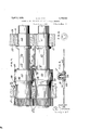
- Fig. 2 is a front View in elevation of said mill.
- Fig. 3 is a sectional view in elevation taken through the center of the mill on a plane at right angles to the roll axes.
- Figs. 4 and 5 are sectional views taken through the center ofthe mill housing on the plane, including the roll axes.
- Fig. 6 is an enlarged detail top plan view of the roll table and'illustrates the table in its relation to the lower roll.
- Fig. 7 is a view, partially in elevation and partially in section, and illustrates the rolls, the roll bearings, and shows a finished disk in section between the rolls.
- Fig. 8 is a view in sectional elevation, taken on a radial line, of the finished disk and the plan view of amill em-' clamping mechanism, for holding the disk'in place on its support pin
- Fig. 9 is a detail view of one of the clamping members.
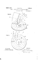
- Figures 10 and 11 illustrate a disk and one of the rolls of the mill and graphically show the flow of the metal.
- the mill shown in the drawings consists of housi11gs lO-lt of ordinary design, brasses 11 and 12 for the lower roll 13, and brasses 15 and 16 for upper roll 17.
- the saddles 18 and i 19 for the'upper roll are mounted on springs 20 and the brasses are provided with cylindrical outer surfaces 21 and 22.
- Brasses of this form are provided for the upper roll in order that the roll may be tilted about point 23 which is assumed to be the point at which the axis of roll 17 cuts the plane of roll end face
- the rolls 13 and 17 are connected together by gears 25 so as to be positively driven at the same speed and the lower roll may be connected up to any suitable prime mover, such as an electric motor, through suitable gearing, not shown, and the customary Wobbler 26.
- Two adjustment screws are provided for each end of the upper roll 17. Those for the gear end of the roll are numbered 27, while those forthe opposite end are numbered 28.
- the upper end of each screw 27 and 28 is squared to receive a .worm wheel 29 provided at its center with a squared hole.
- Worms 30 carried on shafts 31 journaled within housings 32 mesh with worm wheels 29. Housings 32 rest upon the tops of worm Wheels 29'and those for each set of screws are tied together by a tie rod 33.
- WVorm shaft 31 for the adjustment screws for the gear end of the roll 17 carries a worm wheel 34 while worm shaft 31 for the adjustment screws for the opposite end of roll 17 carries a worm wheel 35.
- a shaft 36 journaled within housings 37 and 38 mounted upon worm shaft3l, is provided with worms 39 and 40, which mesh with worms wheels 34 and 35, respectively.
- Shaft 36 is split or divided and the several parts are connected together by means of a aw clutch, one member 11 of which is keyed to one part of shaft 36 and the other part 42 is feathered to the other part of said shaft.
- Shaft 36 by means of suitable couplings 43, is connected up to a prime mover, such as an electric motor 44, under the control of the mill operatives.
- a table 45 preferably of cast iron, supported on suitable supports 46, extends from front to back of the mill and is cut away on each side of the line of rolling, as shown at 47, so as to clear the meeting faces of the rolls.
- the table is provided with a slot which is ofiset at 48, thus providing a forward portion 49 and a rearward portion 50.
- Supporting and guide rollers 51 and 52 carried in brackets secured to the underside of table 45 provide a support for a sliding bar 53, having an operating lever 54 pivotally connected thereto at 55.
- Operating lever 54 is provided with an upstanding pin 56 about which the disks, during rolling, are caused to rotate.
- Rollers 51 and 52 are each formed of two diameters, and bar 53 rides on the portion of smaller diameter, while operating lever 54 at times rides on the portion of larger diameter, as will be apparent from Fig. 6.
- Rolls 13 and 17 are not of ordinary construction. Roll 17, between the active face of its body 57 and its neck 58,'is provided with a waist 59, and similarly roll 13 between the active face of its body 60 and neck 61 is provided with a waist 62.
- the cutting away of the rolls to form these waists accomplishes a twofold purpose. First, it provides room for table 45, the clamping mechanism for the disk to be hereinafter described, and the disk itself; and, second, it provides a certain amount of spring in the rolls which is utilized in level stretching the disks after the major part of the reduction has been accomplished.
- the blanks to be converted in radially tapered disks 63 are clamped between a support 64 having a central thimble-like projection 65 which extends through a hole punched at the center of the blank or disk and a washer 66, which lies on top of the blank surrounding the projection 65, by means of a clamp nut 67.
- Thimble-like projection 65 is exteriorly threaded while lock nut 67 is interiorly threaded. The threads of both are formed in the nature of the threads of a breach block so that the nut can be d ropped into place and upon a quarter turn will firmly clamp the blank 63 between support 64 and washer 66.
- worms 30, with relation to worm wheels 29, is such that as the adjustment screws for one end of roll 17 are turned down those for the other end are backed up.
- the roll bearings, therefore, for one end will be moved down against the stress of itssupport springs 20 while the support springs for the bearings for the other end of the roll will move its bearings up so as to follow the upward movement of the adjusting screws above the same.
- a heating furnace 68 of suitable design is the clamping device is attached thereto.
- table 80 is provided at the delivery endof the mill, onto which the stripper 81 may slide the finished disks 63, where they will be supported while he removes the clamping device.
- the clamping devices, after removal from the finished disk, are conveyed by means of a chute 82 to a bosh 83 filled with cooling water.
- the active face of body 57 of roll 17 is tapered from end face 24 to end face 84 while the active face of body 60 of roll 13 is a true cylinder.
- a shear ring 85 preferably made in halves, is bolted to end face 86 of roll 13 by means of fillister head screws 87. The outer periphery of this shear ring lies flush with the cylindrical surface of the roll body 60.
- A. shear ring 88 bolted to end face 84 of roll body 57 co-operates with shear ring 85 to shear the disks 63 to circular form during the process of rolling.
- the body portion 89 of the thimble-like projection on support 64 is preferably formed octagonal.
- the blank is brought to proper rolling temperature in reheating furnace 68 and at its center for an area of about 10 inches in diameter it is cooled by placing a heavy cold disk upon the blank at its center for the purpose of conducting away the heat at that portion.
- the blank may be heated in such a Way as to prevent the central portion from attaining the heat of the periphery and portions adjacent the periphery. This may be accomplished by constructing the reheating furnace 68 so that the blanks during heating are mounted on water-cooled supports within the furnace; the supports being constructed so as to carry off the heatof the central portion of the blank. Such a furnace is desirable since it central portion.
- the blank After the blank is removed from the reheating furnace 68 with the central portion cooled, it is carried to slide 69 by the heater and placed over the thimble portion of a support 64. A washer 66 is then placed on top of the blank and a clamp nut 67 dropped in place over the thimble and given a quarter turn so as to clamp the blank securely between support 64 and the washer.
- the blank, with the assembled clamp is then mounted on .pin 56 which has been brought to the forward end of slot 49 by the roller by manipulating operating lever 54, and the blank is then move-.l by the roller so that pin 56 lies in the slot offset48. as shown in Fig. 6.
- the roller bymeans of the operating lever, holds thepin in offset 48 and for disks of the dimensions given, the center of the pin, when in the offset, lies,4.58 inches in front of the plane including the roll axes.- It will be un derstood, of course, that before the blank is moved to this position therolls will have been separated sufiiciently to'allow the blank i) enter.
- motor 44 When'the blank has reached this position, motor 44 will be started so that the adjustment screws 27 for the gear end of 'roll 17 will be turned down and adjustment screws 28 for the other end of roll 17 will be backed up and roll 17 thus tilted about point 23 in its axis.
- the speed of motor 44 will depend dead passes to stretch the disk level,,or a
- motor 44 is reversed until the rolls are separated a sufiicient distance to accommodate the next succeeding blank.
- the finished disk is moved by the roller to the rear of table 45. This is done by swinging operating lever 54 to the position shown by dotted line in Fig. 6. In moving the operating lever to this position, pin 56 is carried through the slot offset and along slot 50.
- the stripper by means of a suitable pair of tongs, grabs the finished disk,
- the side 90'of operating lever 54 nearest the gear end of the rolls bears against roll end face 91, and the cylindrical surface 92 of clamp nut 67 bears against end face 24 of roll 17.
- the clamping nut and lever 54 thus form abutments which prevent relative longitudinal motion of the two rolls and positively hold the rolls in proper rolling position with relation to the disk, independent of lateral motion of the disk and the rolls.
- the roll ends 24 and 91 form abutments for pin 56 and, therefore, reduce cross bending strains on the pin occasioned by the lateral pull of the disk during rolling. This is advantageous since the pin may thereby be of minimum diameter and at the same time resist heavy strain without undue deflection.
- This interaction between the pin and roll ends removes the end thrust from the roll bearings and at the same time permits the rolls to have free longitudinal motion without changing their relation with respect to each other and with respect to the disk.
- the cooling of the disk at the center confines the stretching to the hot marginal portion which is that portion subjected to roll action.
- Pin 56 by means of the operating lever 54, will be held by the roller in the slot oflset not only during the reduction passes but during the dead passes.
- the section of the disk under stretchin strain during reduction is of triangular orm, the base being the line of roll contact while the chilled or cooled central part of the disk is the apex.
- the active face of roll 13 will preferably be tapered in the same manner as the active face of roll 17 or both rolls may be cylinders ⁇ if-they are both mounted for simultaneous and opposite tilting.
- the thimble-like projection 65 of the disk clamping device may have to be slightly lengthened so as to accommodate two disks instead of one.
- the plane faces of the disks will lie in contact, one with the other, and
- the tapered faces will lie above and below the plane faces.
- the movable or tilting roll Since the movable or tilting roll has its active face longitudinally hyperbolically incurved or concaved, it will be seen that at the beginning of the rolling operation this roll will contact with the rotating blank at a point adjacent its center or on the hub line and atits periphery.
- the surface of the blank in contact with the tilting roll will be convexed, so that the surface of the blank along all radial lines will not be straight, but will be more or less curved and as the reduction of the blank proceeds, the convexity'decreases until the surface of the finished disk along all radial lines is straight due to roll contact along the entire length of the active face of the roll.
- the pass during the operation of reducing the blank progressively decreases toward the periphery of the blank, so that at the time the disk is finished, the pass at the periphery of the disk has decreased to the minimum distance while that at the hub or adjacent the center remains as it was in the beginning.
- the fiat central circular area is represented by 92 having a pcriphery 92 and from the periphery of this area the disk tapers radially in all directions equally to the disk periphery 93.
- Lines 92 93, 9a and 95 represent the direction of rotation of four points in the disk around pin 56, while the lines A, B, O, and D represent the lines of movement of points in the face of roll 57.
- Lines E, F, G and H represent the components of the two forces represented by the circular lines 92 93, 94 and 95, and the lines A, B, C and D.
- the direction of elongation is represented by line 96 which progresses spirally from the periphery of the circular area 92 to the disk periphery 93.
- the fibre of the disk (due to the method of rolling in which the disk is held for rotation in front of the plane including the roll axes) throughout the entire disk outside of the central area 92 extends along lines similar to line 96 thus producing a disk in which the fibre distribution is substantially symmetrical with relation to the disks center throughout the entire rolled portion of the disk, thus producing extreme strength.
- the method which consists in concaving for at least a portion of its length the active face of at least one roll of a pair, in supporting a blank for rotation about a center outside of the plane including the axes of said rolls, and in roller-forging said blank between said rolls.
- the method ofmaking radially tapered disks which consists in roller forging a blank between a pair of rolls and providing at least a portion of the active face of at least one of said rolls with a longitudinally concaved surface and in supporting said blank so as to rotate about a fixed center behind the plane including the roll axes whereby the blank is rolled off center.
- the method of making radially tapered disks which consists in supporting a blank for rotation and in roller forging said blank by means of rolls on a contact line which is outside of the center about which the blank rotates during rolling and incurving the active face of at least one of said rolls along the line of rolling to conform to the finished disk along said line.
- the method which consists in so forming a pair of rolls that the active face of at least one is incurved from end-to-end, in reducing a metal blank between said rolls, and during reduction in holding the blank in such manner that it is forced by the rolls to rotate about a fixed center outside of the plane which includes the roll axes.
- the method of making radially tapered disks which, consists in entering a blank between .rolls and holding the center of the blank behind the plane including the roll axes, in revolving said rolls and simultaneously therewith in tilting one of said rolls toward the other.
- the method of making radially tapered disks which consists in enterlng a metal blank between rolls, in holding the center of the blank outside of the plane including the roll axes, in revolving said rolls in contact with the blank and in changing the angle between the roll axes during roll- 14.
- the method of formin tapered disks which consists in confining a blank at an 1ntermediate point so that it is capable of turning, then in subjectingthe blank to the action of rolls so that the confining elements bear against the end of the rolls as the blank is turned by the roll action.
- tapered dlsks which consists in so confining a blank at an intermediate point that it is ca able of rotating about the confined portion, then in subjecting the blank to roll action so that it is rotated and so that at least one of the confining elements is held in engagement with the end of one of the rolls.
- the line of rolling extends at an angle to radial lines, whereby one confining element is held in contact with a roll end by the action of the rolls on the blank.
- the method whichv consists in so heating a metal blank of substantially uniform thickness as to obtain a relatively cold central zone with the surrounding border raised to rolling temperature, in rotating the blank about a point in the central zone andthen in roller forge beveling theblank during rotation thereof.
- a pair ofrolls one at least of which has its active face incurved from end to end, means for tilting one ofsaid rolls toward the other duringrolling in the plane common to the roll axes, and means for supporting a blank for rotation during rolling about a center behind said plane.
- a pair of rolls means for tilting one of said rolls toward the other during rolling in a plane common to the roll axes and means for supporting superposed blanks for rotation by said rolls about a common center outside of said plane.
- a pair of rolls having their axes angularly disposed in the'same plane, means for supporting a blank for rotation by said rolls about a center in front of the plane common to the roll axes and means for decreasing the distance between the rolls during rolling.
- a pair of rolls driving means for said rolls, means for holding the center of a blank during rolling beyond the plane including the roll axes and means for tilting one of said rolls about a point located in its axis and beriphery.
Description
0. M. OTTE April 9, 1929.
METHOD OF ROLLING DISKS AND ROLLING MILL THEREFOR Filed Sept. 5, 1921 6 Sheets-Sheet l INVEAITOI? a; M. 0W1 L AW. \zcmlz L; W .4, 1 A:
April 9, 1929. o, OTTE 1,708,321
METHOD OF ROLLING DISKS AND ROLLING MILL THEREFOR Filed Sept. 5, 1921 6 Sheets-Sheet 2 FIELZ.
INVEN 7'01? ML, M. 0111 Row. \JCM mam ALA Q C). M. QTTE April 9, 1929.
METHOD OF ROLLING DISKS AND ROLLING MILL THEREFOR 6 Sheets-Sheet 3 Filed Sept. 5, 1921 o. M. QTTE 1,708,321
METHOD OF ROLLING DISKS AND ROLLING MILL THEREFOR Filed Sept. 5, 1921 6 Sheets-Sheet 4 U m w April 9, 1929.
0. M. QTTE April 9, 1929.
METHOD OF ROLLING DIS-KS AND ROLLING MILL THEREFOR 6 Sheets-Sheet 5 I i w fi I Wu O \m Em I 1 omfwmw m w W v :i m .6 KW I mw H April 9, 1929. Q M'.OTTE 1,708,321
METHOD OF ROLLING DISKS AND ROLLING MILL THEREFOR Filed Sept. 5, 1921 6 Sheets-Sheet 6 WITNESSES Patented Apr. 9, 1929.
A 1,708,321 PATENT OFFICE.
OTHO M. OT'IE, OF TARENTUM, PENNSYLVANIA, ASSIGNOR TO ALLEGHENY STEEL COMPANY, OF BRACKENRIDGE, PENNSYLVANIA, A CORPORATION OF ENNSYL- VAN IA.
METHOD OF ROLLING DISKS AND ROLLING MILL THEREFOR.
Application filed September 3, 1921. Serial No. 498,350.
used for motor vehicles and in the fabrication of one of these a steel disk 28.5 inches in diameter, flat on one side and on the. other tapered radially from a central flat area inches in diameter, is used. The central'area IQ, is .197 inches in thickness and the disk from this central area tapers to .071 inchesin thickness at its outer periphery. Various methods have been used in the manufacture of these disks but with all of those methods with which I am familiar the cost is excessive and by none of them is it possible to commercially produce balanced disks.
An object of this invention is to provide a 24 method and mill for rolling balanced radially tapered metal disks.
A further object is to provide a methodand mill whereby these or similar radially tapered disks may be cheaply and quickly rolled to accurate measurement, thus doing away with costly machine or grinding operations.
A still further object is to provide a method and mill whereby two such disks, incontact one with the other, may be simultaneously rolled by one pair of rolls.
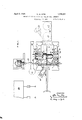
These, as well as other objects which will readily appear to those skilled in this art, I attain by the method and mill described in the specification and illustrated in the drawings accompanying and forming a part of this application and in which Figure 1 is a top bodying this invention.
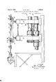
Fig. 2 is a front View in elevation of said mill.
Fig. 3 is a sectional view in elevation taken through the center of the mill on a plane at right angles to the roll axes.
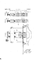
Figs. 4 and 5 are sectional views taken through the center ofthe mill housing on the plane, including the roll axes.
Fig. 6 is an enlarged detail top plan view of the roll table and'illustrates the table in its relation to the lower roll.
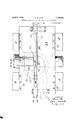
Fig. 7 is a view, partially in elevation and partially in section, and illustrates the rolls, the roll bearings, and shows a finished disk in section between the rolls.
Fig. 8 is a view in sectional elevation, taken on a radial line, of the finished disk and the plan view of amill em-' clamping mechanism, for holding the disk'in place on its support pin, Fig. 9 is a detail view of one of the clamping members.
Figures 10 and 11 illustrate a disk and one of the rolls of the mill and graphically show the flow of the metal.
The mill shown in the drawings consists of housi11gs lO-lt of ordinary design, brasses 11 and 12 for the lower roll 13, and brasses 15 and 16 for upper roll 17. The saddles 18 and i 19 for the'upper roll are mounted on springs 20 and the brasses are provided with cylindrical outer surfaces 21 and 22. Brasses of this form are provided for the upper roll in order that the roll may be tilted about point 23 which is assumed to be the point at which the axis of roll 17 cuts the plane of roll end face The rolls 13 and 17 are connected together by gears 25 so as to be positively driven at the same speed and the lower roll may be connected up to any suitable prime mover, such as an electric motor, through suitable gearing, not shown, and the customary Wobbler 26.
Two adjustment screws are provided for each end of the upper roll 17. Those for the gear end of the roll are numbered 27, while those forthe opposite end are numbered 28. The upper end of each screw 27 and 28 is squared to receive a .worm wheel 29 provided at its center with a squared hole. Worms 30 carried on shafts 31 journaled within housings 32 mesh with worm wheels 29. Housings 32 rest upon the tops of worm Wheels 29'and those for each set of screws are tied together by a tie rod 33.
WVorm shaft 31 for the adjustment screws for the gear end of the roll 17 carries a worm wheel 34 while worm shaft 31 for the adjustment screws for the opposite end of roll 17 carries a worm wheel 35. A shaft 36, journaled within housings 37 and 38 mounted upon worm shaft3l, is provided with worms 39 and 40, which mesh with worms wheels 34 and 35, respectively. Shaft 36 is split or divided and the several parts are connected together by means of a aw clutch, one member 11 of which is keyed to one part of shaft 36 and the other part 42 is feathered to the other part of said shaft. Shaft 36, by means of suitable couplings 43, is connected up to a prime mover, such as an electric motor 44, under the control of the mill operatives. A table 45, preferably of cast iron, supported on suitable supports 46, extends from front to back of the mill and is cut away on each side of the line of rolling, as shown at 47, so as to clear the meeting faces of the rolls. The table is provided with a slot which is ofiset at 48, thus providing a forward portion 49 and a rearward portion 50.
Supporting and guide rollers 51 and 52 carried in brackets secured to the underside of table 45 provide a support for a sliding bar 53, having an operating lever 54 pivotally connected thereto at 55. Operating lever 54 is provided with an upstanding pin 56 about which the disks, during rolling, are caused to rotate.
Rolls 13 and 17 are not of ordinary construction. Roll 17, between the active face of its body 57 and its neck 58,'is provided with a waist 59, and similarly roll 13 between the active face of its body 60 and neck 61 is provided with a waist 62. The cutting away of the rolls to form these waists accomplishes a twofold purpose. First, it provides room for table 45, the clamping mechanism for the disk to be hereinafter described, and the disk itself; and, second, it provides a certain amount of spring in the rolls which is utilized in level stretching the disks after the major part of the reduction has been accomplished.
The blanks to be converted in radially tapered disks 63 (one of which is shown in section) are clamped between a support 64 having a central thimble-like projection 65 which extends through a hole punched at the center of the blank or disk and a washer 66, which lies on top of the blank surrounding the projection 65, by means of a clamp nut 67. Thimble-like projection 65 is exteriorly threaded while lock nut 67 is interiorly threaded. The threads of both are formed in the nature of the threads of a breach block so that the nut can be d ropped into place and upon a quarter turn will firmly clamp the blank 63 between support 64 and washer 66.
The arrangement of worms 30, with relation to worm wheels 29, is such that as the adjustment screws for one end of roll 17 are turned down those for the other end are backed up. The roll bearings, therefore, for one end will be moved down against the stress of itssupport springs 20 while the support springs for the bearings for the other end of the roll will move its bearings up so as to follow the upward movement of the adjusting screws above the same.
A heating furnace 68 of suitable design is the clamping device is attached thereto. A
table 80 is provided at the delivery endof the mill, onto which the stripper 81 may slide the finished disks 63, where they will be supported while he removes the clamping device. The clamping devices, after removal from the finished disk, are conveyed by means of a chute 82 to a bosh 83 filled with cooling water.
The active face of body 57 of roll 17 is tapered from end face 24 to end face 84 while the active face of body 60 of roll 13 is a true cylinder.
A shear ring 85, preferably made in halves, is bolted to end face 86 of roll 13 by means of fillister head screws 87. The outer periphery of this shear ring lies flush with the cylindrical surface of the roll body 60. A. shear ring 88 bolted to end face 84 of roll body 57 co-operates with shear ring 85 to shear the disks 63 to circular form during the process of rolling.
The body portion 89 of the thimble-like projection on support 64 is preferably formed octagonal.
For the purpose of rolling a radially tapered disk of the dimensions given, I take, for example, a circular blank .197inches in thickness, 22.125 inches in diameter and having an octagonal hole punched at its center to fit the octagonal portion 89 of the thimble. The blank is brought to proper rolling temperature in reheating furnace 68 and at its center for an area of about 10 inches in diameter it is cooled by placing a heavy cold disk upon the blank at its center for the purpose of conducting away the heat at that portion. The blank may be heated in such a Way as to prevent the central portion from attaining the heat of the periphery and portions adjacent the periphery. This may be accomplished by constructing the reheating furnace 68 so that the blanks during heating are mounted on water-cooled supports within the furnace; the supports being constructed so as to carry off the heatof the central portion of the blank. Such a furnace is desirable since it central portion.
After the blank is removed from the reheating furnace 68 with the central portion cooled, it is carried to slide 69 by the heater and placed over the thimble portion of a support 64. A washer 66 is then placed on top of the blank and a clamp nut 67 dropped in place over the thimble and given a quarter turn so as to clamp the blank securely between support 64 and the washer. The blank, with the assembled clamp, is then mounted on .pin 56 which has been brought to the forward end of slot 49 by the roller by manipulating operating lever 54, and the blank is then move-.l by the roller so that pin 56 lies in the slot offset48. as shown in Fig. 6.
The roller, bymeans of the operating lever, holds thepin in offset 48 and for disks of the dimensions given, the center of the pin, when in the offset, lies,4.58 inches in front of the plane including the roll axes.- It will be un derstood, of course, that before the blank is moved to this position therolls will have been separated sufiiciently to'allow the blank i) enter.
When'the blank has reached this position, motor 44 will be started so that the adjustment screws 27 for the gear end of 'roll 17 will be turned down and adjustment screws 28 for the other end of roll 17 will be backed up and roll 17 thus tilted about point 23 in its axis. The speed of motor 44 will depend dead passes to stretch the disk level,,or a
number of such passes sufficient to iron out the major part of the waves or corrugations which have appeared in thedisk during rolling. It will be understood that .the mill, so far as the rolls are concerned, revolves continuou'sly.
After the disks have been stretched level by the dead passes, motor 44 is reversed until the rolls are separated a sufiicient distance to accommodate the next succeeding blank. During the time the rolls are being separated, the finished disk is moved by the roller to the rear of table 45. This is done by swinging operating lever 54 to the position shown by dotted line in Fig. 6. In moving the operating lever to this position, pin 56 is carried through the slot offset and along slot 50. When the finished disk reaches the rear end of table 45, the stripper, by means of a suitable pair of tongs, grabs the finished disk,
slides it to table 80, removes the clamping dev1ce and places the several parts thereof in chute 82 by means of which it is transferred I to bosh 83 for cooling and reuse.
The side 90'of operating lever 54 nearest the gear end of the rolls bears against roll end face 91, and the cylindrical surface 92 of clamp nut 67 bears against end face 24 of roll 17. The clamping nut and lever 54 thus form abutments which prevent relative longitudinal motion of the two rolls and positively hold the rolls in proper rolling position with relation to the disk, independent of lateral motion of the disk and the rolls. In turn, the roll ends 24 and 91 form abutments for pin 56 and, therefore, reduce cross bending strains on the pin occasioned by the lateral pull of the disk during rolling. This is advantageous since the pin may thereby be of minimum diameter and at the same time resist heavy strain without undue deflection. This interaction between the pin and roll ends removes the end thrust from the roll bearings and at the same time permits the rolls to have free longitudinal motion without changing their relation with respect to each other and with respect to the disk.
As before said, it has been found desirable to have the roll waists 59 and 62 of such flexibility that the spring of the same will exert such pressure during the dead passes as to cause gripping of the disk by the rolls sufficient to stretch the same level during comparatively few complete revolutions of the disk. Of course, during this level stretching, a slight reduction of the disk will take place.
I find that by holding the blank, as shown in Fig. 6, so that pin 56, about which it ro tates during rolling, lies in front of the plane including the roll axes and beyond the ends 24 and 91 of the active roll faces, the blank is simultaneously roll reduced at one portion and stretched at another. The rolling takes place off the center of the disk or, in other words, at an angle to a radial line of the disk and the disk is stretched during rolling between the roll contact line and the disk centre, since the movement of the disk through the roll is resisted by the pin which is held stationary in the slot ofiset.
The cooling of the disk at the center confines the stretching to the hot marginal portion which is that portion subjected to roll action. Pin 56, by means of the operating lever 54, will be held by the roller in the slot oflset not only during the reduction passes but during the dead passes. The section of the disk under stretchin strain during reduction is of triangular orm, the base being the line of roll contact while the chilled or cooled central part of the disk is the apex.
If two disks are to be simultaneously rolled, then the active face of roll 13 will preferably be tapered in the same manner as the active face of roll 17 or both rolls may be cylinders \if-they are both mounted for simultaneous and opposite tilting.
If two disks are to be simultaneously rolled, the thimble-like projection 65 of the disk clamping device may have to be slightly lengthened so as to accommodate two disks instead of one. When two disks are simultaneously rolled, the plane faces of the disks will lie in contact, one with the other, and
the tapered faces will lie above and below the plane faces.
Whenever I have spoken of the rolls as either tapered or as cylinders, it will be understood that'when the roll is tapered or is mounted for tilting, whether tapered or a cylinder, the active roll face must conform to the contour of the finished disk along the roll (the one in contact with the tapered side of the disk) of such contour that the roll contact line will conform to the surface of the finished disk along the line of rolling. It will, therefore, be obvious since the disks are truncated cones, that the active face of the roll in contact with the tapered side of the.
disk must be hyperbolically incurved or concaved in order to conform to the contour of the finished disk along the line of rolling.
Since the movable or tilting roll has its active face longitudinally hyperbolically incurved or concaved, it will be seen that at the beginning of the rolling operation this roll will contact with the rotating blank at a point adjacent its center or on the hub line and atits periphery. During the initial steps of reduction the surface of the blank in contact with the tilting roll will be convexed, so that the surface of the blank along all radial lines will not be straight, but will be more or less curved and as the reduction of the blank proceeds, the convexity'decreases until the surface of the finished disk along all radial lines is straight due to roll contact along the entire length of the active face of the roll.
The pass during the operation of reducing the blank progressively decreases toward the periphery of the blank, so that at the time the disk is finished, the pass at the periphery of the disk has decreased to the minimum distance while that at the hub or adjacent the center remains as it was in the beginning.
. gether with the device and modification there- '5 of which I now consider to represent the best 6 In Figures 10 and 11 the fiat central circular area is represented by 92 having a pcriphery 92 and from the periphery of this area the disk tapers radially in all directions equally to the disk periphery 93. Lines 92 93, 9a and 95 represent the direction of rotation of four points in the disk around pin 56, while the lines A, B, O, and D represent the lines of movement of points in the face of roll 57. Lines E, F, G and H represent the components of the two forces represented by the circular lines 92 93, 94 and 95, and the lines A, B, C and D. The direction of elongation is represented by line 96 which progresses spirally from the periphery of the circular area 92 to the disk periphery 93.
The fibre of the disk (due to the method of rolling in which the disk is held for rotation in front of the plane including the roll axes) throughout the entire disk outside of the central area 92 extends along lines similar to line 96 thus producing a disk in which the fibre distribution is substantially symmetrical with relation to the disks center throughout the entire rolled portion of the disk, thus producing extreme strength.
In accordance with the provisions of the Patent Statutes, I have described the principle of the operation of my invention, to-
embodiments thereof, but I desire to have it understood that the devices shown are only illustrative and that the invention can be carried out in other ways.
Having thus described my invention, what I claim as new and desire to secure by Let- .ters Patent is:
1. The method of making. radially tapered disks, which consists in roller forging a blank between a pair of rolls, and during rolling in moving one roll about a point between the center and periphery of the blank to decrease the pass.
2. The method of making radially tapered disks, which consists in roller forging a blank between a pair of rolls, and during rolling in constantly moving one roll about a point between the center and periphery of the blank to decrease the pass at the periphery of the blank while maintaining the pass adjacent the center of the blank.
3. The method of making radially tapered disks, which consists in so supporting a blank for rotation between a pair of'rolls that the roll contact line is outside of the center about which the blank rotates during rolling and in changing the angle between the roll axes during rolling.
4. The method of making radially tapered disks, which consists in so supporting a blank for rotation between a pair of rolls that the contact line is outside of the center about which the blank rotates during rolling and in constantly changing the angle between the roll axes during rolling.
5. The method of making radially tapered disks, which consists inroller forging a blank between a pair of rolls, locating the axes of said rolls so as to lie in a common plane outside the center of the blank and in progressively varying the angle between the roll axes during rolling by tilting one of said rolls toward the other.
6. The method which consists in concaving for at least a portion of its length the active face of at least one roll of a pair, in supporting a blank for rotation about a center outside of the plane including the axes of said rolls, and in roller-forging said blank between said rolls.
7. The method ofmaking radially tapered disks, which consists in roller forging a blank between a pair of rolls and providing at least a portion of the active face of at least one of said rolls with a longitudinally concaved surface and in supporting said blank so as to rotate about a fixed center behind the plane including the roll axes whereby the blank is rolled off center.
8. The method which consists in incurving a portion of the active face of at least one roll of a pair of rolls, in forging a blank between said rolls, and in supporting the blank during rolling to maintain its axes of rotation outside of the plane including the roll axes.
between the center and 9. The method of making radially tapered disks, which consists in supporting a blank for rotation and in roller forging said blank by means of rolls on a contact line which is outside of the center about which the blank rotates during rolling and incurving the active face of at least one of said rolls along the line of rolling to conform to the finished disk along said line.
10. The method which consists in so forming a pair of rolls that the active face of at least one is incurved from end-to-end, in reducing a metal blank between said rolls, and during reduction in holding the blank in such manner that it is forced by the rolls to rotate about a fixed center outside of the plane which includes the roll axes.
11. The method of making radially tapered disks, which, consists in entering a blank between .rolls and holding the center of the blank behind the plane including the roll axes, in revolving said rolls and simultaneously therewith in tilting one of said rolls toward the other.
12. The method of making radially tapered disks, which consists in entering a blank between rolls and holding the center of the blank behind the plane including the roll axes, in revolving said rolls and simultaneously therewith. in tilting one of said rolls toward the other about apoint located periphery of the blank.
13. The method of making radially tapered disks, which consists in enterlng a metal blank between rolls, in holding the center of the blank outside of the plane including the roll axes, in revolving said rolls in contact with the blank and in changing the angle between the roll axes during roll- 14. The method of formin tapered disks which consists in confining a blank at an 1ntermediate point so that it is capable of turning, then in subjectingthe blank to the action of rolls so that the confining elements bear against the end of the rolls as the blank is turned by the roll action.
15. The method of forming tapered dlsks which consists in so confining a blank at an intermediate point that it is ca able of rotating about the confined portion, then in subjecting the blank to roll action so that it is rotated and so that at least one of the confining elements is held in engagement with the end of one of the rolls.
16. The method of forming tapered disks whichconsists in confining a blank at an intermediate point so that it is capable of rotation thereabout, then in so subjecting the blank to the action of (lo-operating rolls that.
the line of rolling extends at an angle to radial lines, whereby one confining element is held in contact with a roll end by the action of the rolls on the blank.
ing a metal blank of substantially uniform thickness that an area adjacent its center is relatively cold, while the surrounding portion is raised to rolling temperature, then in roller beveling the surrounding portion during rotation of the blank about a center out side of the plane including the roll axes.
19. The method whichv consists in so heating a metal blank of substantially uniform thickness as to obtain a relatively cold central zone with the surrounding border raised to rolling temperature, in rotating the blank about a point in the central zone andthen in roller forge beveling theblank during rotation thereof.
20. The method of making radially tapered disks, which consists in forming a convex face on one side of a metal blank of substantially uniform thickness and then in reducing the convexity" of said face. i
21. The method of making radially tapered disks, which consists in rolling a metal blank to form a convex face on one side theregf and then in reducing the convexity of said ace.
22. The method of making radially tapered disks, which consists in rolling a metal blank to form a convex face on one side thereof and then in roll reducing the convexity of said face. a
23. The method of rolling a radially tapered circular disk, which consists in formin a convex face on at least one side of a meta blank during initial displacement of the metal of the blank and subsequently reducing the convexity of said face by further displacement of the metal of the blank.
24. The method of making radially tapered disks, which consists in simultaneously forming convex faces on opposite sides of superposed metal blanks and then in simulganeously reducing the convexity of said aces.
25. The method of making radially tit-- pered disks, which consists in increasing the diameter of a metal blank and simultaneously therewith informing a convex face on one side thereof and during further-increase in the diameter in reducing the convexity of said face.
26. In a mill for rolling radially tapered disks, a pair of rolls one at leastof which has its active face incurved from end to end, means for tilting one of said rolls toward the other during rolling in the plane common to the roll axes, and means for su porting a tween the center of the blank and its pe- 4 blank for rotation during rolling a out a center outside of said plane.
27. In a mill for rolling radially tapered disks, a pair ofrolls one at least of which has its active face incurved from end to end, means for tilting one ofsaid rolls toward the other duringrolling in the plane common to the roll axes, and means for supporting a blank for rotation during rolling about a center behind said plane.
28. In a mill for rolling radially tapered disks, a pair of rolls, gears connecting said rolls, means for moving one of said rolls toward and from the other for entering and removing the work, means for constantly changing the angle between the roll axes during rolling and means for supporting a blank for rotation by said rolls,
29. In a mill forrolling radially tapered disks, a pair of rolls, means for tilting one of said rolls toward the other during rolling in a plane common to the roll axes and means for supporting superposed blanks for rotation by said rolls about a common center outside of said plane.
30. In a mill for rolling radially tapered disks, a pair of rolls having their axes angularly disposed in the'same plane, means for supporting a blank for rotation by said rolls about a center in front of the plane common to the roll axes and means for decreasing the distance between the rolls during rolling.
31. In a mill for rolling radially tapered disks, a pair of rolls, driving means for said rolls, means for holding the center of a blank during rolling beyond the plane including the roll axes and means for tilting one of said rolls about a point located in its axis and beriphery.
32. In a mill for rolling radially tapered disks, a pair of rolls, gears connecting said rolls, driving means for said rolls, adjustment screws for said rolls and means for simultaneously moving said screws in opposite direc- ,tions.
33. In a mill for rolling radially tapered disks, a pair of rolls, bearings for the opposite ends of said rolls, means for pivotally supportinga blank between said bearings, adjustment screws for the bearings of one roll, springs for supporting said bearings and means for simultaneously moving said screws in opposite directions.
34. In a mill for rolling radially tapered disks, a pair of rolls, means located beyond the end of theactive faces of said rolls for pivotally supporting a blank being rotated by said rolls, roll bearings located on the opposite side of the said means, adjustment screws for said bearings, and means for simultaneously moving said adjustment screws in opposite longitudinal directions.
35. In a mill for rolling radially tapered disks, a pair of rolls, a table extending between said rolls, a guide slot in said table, pin supporting means, a pin on said supporting means extending through said slot, a bearing for a blank mounted on said pin, adjustment screws for the opposite ends of one of said rolls and means for simultaneously moving said screws in opposite directions to tilt said roll.
In testimony whereof, I have hereunto subscribed my name this 26th day of August,
I OTHO orrs.
Priority Applications (1)
| Application Number | Priority Date | Filing Date | Title |
|---|---|---|---|
| US498350A US1708321A (en) | 1921-09-03 | 1921-09-03 | Method of rolling disks and rolling mill therefor |
Applications Claiming Priority (1)
| Application Number | Priority Date | Filing Date | Title |
|---|---|---|---|
| US498350A US1708321A (en) | 1921-09-03 | 1921-09-03 | Method of rolling disks and rolling mill therefor |
Publications (1)
| Publication Number | Publication Date |
|---|---|
| US1708321A true US1708321A (en) | 1929-04-09 |
Family
ID=23980708
Family Applications (1)
| Application Number | Title | Priority Date | Filing Date |
|---|---|---|---|
| US498350A Expired - Lifetime US1708321A (en) | 1921-09-03 | 1921-09-03 | Method of rolling disks and rolling mill therefor |
Country Status (1)
| Country | Link |
|---|---|
| US (1) | US1708321A (en) |
Cited By (1)
| Publication number | Priority date | Publication date | Assignee | Title |
|---|---|---|---|---|
| US2647423A (en) * | 1946-08-07 | 1953-08-04 | Motor Wheel Corp | Machine for rolling tapered disks |
-
1921
- 1921-09-03 US US498350A patent/US1708321A/en not_active Expired - Lifetime
Cited By (1)
| Publication number | Priority date | Publication date | Assignee | Title |
|---|---|---|---|---|
| US2647423A (en) * | 1946-08-07 | 1953-08-04 | Motor Wheel Corp | Machine for rolling tapered disks |
Similar Documents
| Publication | Publication Date | Title |
|---|---|---|
| US11484924B2 (en) | Device and method for forming shaft part by two-roller flexible skew rolling | |
| US2054182A (en) | Method and apparatus for threading hollow metal articles | |
| US1708321A (en) | Method of rolling disks and rolling mill therefor | |
| US2084746A (en) | Straightening machine for long stock | |
| US2060768A (en) | Tube mill | |
| US2099497A (en) | Guide for tube rolling mills | |
| CN105057346A (en) | Planetary gear train-groove cam type bar end hot-forming mechanism | |
| US4238944A (en) | Rolling of stepped shafts | |
| EP3450038B1 (en) | Rolling stand for a rolling mill and universal rolling mill comprising said rolling stand | |
| US2269899A (en) | Apparatus for forging and forming balls | |
| US558591A (en) | medart | |
| US1772538A (en) | Method and apparatus for die rolling | |
| US1986072A (en) | Device for the manufacture of shaped pieces from annular blanks | |
| US1606875A (en) | Metal-rolling mill | |
| Kalyani et al. | The effect of force parameter on profile ring rolling process | |
| US2409649A (en) | Ball forming mill | |
| US1606903A (en) | Process of and apparatus for rolling metallic disks | |
| US419292A (en) | Method of making irregular-shaped metal articles | |
| US855658A (en) | Apparatus for nurling cylinders. | |
| US1923389A (en) | Method of hot rolling radially tapered disks | |
| US2206759A (en) | Cross rolling | |
| US2357058A (en) | Apparatus for rolling rounds | |
| US2388249A (en) | Rolling mill | |
| US1970121A (en) | Cross rolling machine | |
| US1033569A (en) | Method of manufacturing rifled pipes. |