US1694271A - Combined back fire and theft preventing device - Google Patents
Combined back fire and theft preventing device Download PDFInfo
- Publication number
- US1694271A US1694271A US192459A US19245927A US1694271A US 1694271 A US1694271 A US 1694271A US 192459 A US192459 A US 192459A US 19245927 A US19245927 A US 19245927A US 1694271 A US1694271 A US 1694271A
- Authority
- US
- United States
- Prior art keywords
- spindle
- induction pipe
- obturating member
- lock
- preventing device
- Prior art date
- Legal status (The legal status is an assumption and is not a legal conclusion. Google has not performed a legal analysis and makes no representation as to the accuracy of the status listed.)
- Expired - Lifetime
Links
- 230000006698 induction Effects 0.000 description 34
- 239000007789 gas Substances 0.000 description 12
- 238000002485 combustion reaction Methods 0.000 description 10
- 239000007787 solid Substances 0.000 description 3
- 230000005484 gravity Effects 0.000 description 2
- 241000287181 Sturnus vulgaris Species 0.000 description 1
- 230000005540 biological transmission Effects 0.000 description 1
- 230000004048 modification Effects 0.000 description 1
- 238000012986 modification Methods 0.000 description 1
Images
Classifications
-
- F—MECHANICAL ENGINEERING; LIGHTING; HEATING; WEAPONS; BLASTING
- F16—ENGINEERING ELEMENTS AND UNITS; GENERAL MEASURES FOR PRODUCING AND MAINTAINING EFFECTIVE FUNCTIONING OF MACHINES OR INSTALLATIONS; THERMAL INSULATION IN GENERAL
- F16K—VALVES; TAPS; COCKS; ACTUATING-FLOATS; DEVICES FOR VENTING OR AERATING
- F16K35/00—Means to prevent accidental or unauthorised actuation
- F16K35/10—Means to prevent accidental or unauthorised actuation with locking caps or locking bars
-
- Y—GENERAL TAGGING OF NEW TECHNOLOGICAL DEVELOPMENTS; GENERAL TAGGING OF CROSS-SECTIONAL TECHNOLOGIES SPANNING OVER SEVERAL SECTIONS OF THE IPC; TECHNICAL SUBJECTS COVERED BY FORMER USPC CROSS-REFERENCE ART COLLECTIONS [XRACs] AND DIGESTS
- Y10—TECHNICAL SUBJECTS COVERED BY FORMER USPC
- Y10T—TECHNICAL SUBJECTS COVERED BY FORMER US CLASSIFICATION
- Y10T137/00—Fluid handling
- Y10T137/7069—With lock or seal
- Y10T137/7131—Common lock and valve actuator
- Y10T137/7225—Mechanical movement between lock and valve
-
- Y—GENERAL TAGGING OF NEW TECHNOLOGICAL DEVELOPMENTS; GENERAL TAGGING OF CROSS-SECTIONAL TECHNOLOGIES SPANNING OVER SEVERAL SECTIONS OF THE IPC; TECHNICAL SUBJECTS COVERED BY FORMER USPC CROSS-REFERENCE ART COLLECTIONS [XRACs] AND DIGESTS
- Y10—TECHNICAL SUBJECTS COVERED BY FORMER USPC
- Y10T—TECHNICAL SUBJECTS COVERED BY FORMER US CLASSIFICATION
- Y10T137/00—Fluid handling
- Y10T137/7722—Line condition change responsive valves
- Y10T137/7837—Direct response valves [i.e., check valve type]
- Y10T137/7838—Plural
- Y10T137/7842—Diverse types
-
- Y—GENERAL TAGGING OF NEW TECHNOLOGICAL DEVELOPMENTS; GENERAL TAGGING OF CROSS-SECTIONAL TECHNOLOGIES SPANNING OVER SEVERAL SECTIONS OF THE IPC; TECHNICAL SUBJECTS COVERED BY FORMER USPC CROSS-REFERENCE ART COLLECTIONS [XRACs] AND DIGESTS
- Y10—TECHNICAL SUBJECTS COVERED BY FORMER USPC
- Y10T—TECHNICAL SUBJECTS COVERED BY FORMER US CLASSIFICATION
- Y10T137/00—Fluid handling
- Y10T137/8593—Systems
- Y10T137/877—With flow control means for branched passages
- Y10T137/87829—Biased valve
- Y10T137/87837—Spring bias
- Y10T137/87845—For valve having a ball head
Definitions
- the present invention relates to a back tire and theft preventing device for automobile vehicles, when the engines of these vehicles are of the internal combustion type.
- the device comprises an obturating member, such as a flap valve, mounted in the induction pipe of the engine and opening to wards the engine, in combination with a lock located in such manner as to block the obturating member in its closed position.
- an obturating member such as a flap valve
- the obturating member is constituted by a flap valve
- this flap valve oscillates freely about a spindle eccentric to the center of the flap valve, so that the flap valve tends to close the induction pipe by its own weight.
- the consequence of a backfire is to tilt the flap valve and close the induction pipe.
- Port holes are formed in the wall of the induction pipe, between the obturating memher and the engine, to enable the back-fire gases to escape into the atmosphere, and these port holes are each sealed by an arresting member such as a valve, ball or flap-valve opening towards the exterior of the induction pipe.
- a wire gauze is located within each port hole to arrest the flame before it leaves the apparatus.
- the obturating member and the arresting members maybe mounted on a flange inserted in the induction pipe.
- the spindle of this latter is actuated by the lock and has a lug which, when the spindle is rotated under the action of the lock, comes into contact with the flap valve and closes it.
- the obturating mem- 4 her may be protected against access thereto through the exhaust ports, by providing opposite these latter and around the obturating' member, solid shields which may be integral with the body of the device.
- the lock may either be mounted directly on the apparatus, or on the dash-board, in which case it is connected to the locking spindle by any suitable means of control.
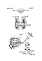
- Fig. 1 is a sectional plan view of the flap valve device.
- Fig. 2 is a vertical axial section of the device shown in Fig. 1..
- Figs. 3 and 4 are detail views.
- the obturating member is constituted by a flap valve 12 loosely mounted on the spindle 13 so that the action of the induced gases and back-fires on the flap valve is to tilt it without causing the spindle to rotate;
- This spindle 13 is at one side of the center of gravity of the flap valve; so that the valve 12 normally tends-to obturate the induction pipe under the action of its weight.
- a lug 14c isfixed to the spindle 13 within the induction pipe, the object of which is to bear against the valve (if it is in the open position) and to close it when the spindle is rotated through an angle of about 90 by means of the lock 25.
- the valve 12 will thus be kept closed by the lug 14: and it will be impossible for the gases to be drawn into the engine.
- the said spindle 13 may, at the same time as it closes the valve, come into engagement with the studs 2 by means of which such flange is-secured so as to prevent the. studs from being removed while the spindle 13 holds the valve 12 in closed position.
- a notch 15 is cut in the periphery of the spindle 13, and a notch 16 1s made opposite itin theperiphery of one of the fixing studs 2.
- the ports 20 may be formed in the induction pipe, between the obturating member and the engine, in order to let the backfire gases exhaust to the a"mosphere. These ports 20 are each closed by an arresting member such as a poppet valve 21, a ball valve 22 or flap valve 23 opening outwards. A wire gauze 24, located within each port arrests the flames before they issue from the apparatus.
- the obturating member can be protected against access thereto through the exhaust ports 20, by providing solid shields 28 in the in duction pipe opposite said ports and around the obturating member, and which may be integral with the body of the device.
- the lock 25 of any suitable form, which actuates the spindle may be mounted either directly on the apparatus, or on the dashboard 26 (Fig. 1), in which case it is connected to the locking spindle by any suitable means of control; thismeans of control is represented by a rod 27 and a universal joint in Fig. 1. r
- a combined theft and back-fire preventing device located in the induct-ion pipe of an internal combustion engine comprising an obturating member located in said induction pipe and opening towards said engine, a lock, and means actuated by said lock for maintaining said obturating member in closed position.
- a combined theft and back-fire preventing device located in the induction pipe of an internal combustion engine comprising an obturating member located in said induction pipe and opening towards said engine, said obturating member being pivoted about an axis offset fromits center of gravity, a lock, and means actuated by said lock for maintaining said obturating member in closed position.
- a combined theft and back-fire preventing device located in the induction pipe ofan internal combustion engine comprising an obturating member located in said induction pipe and opening towards said engine, a spindle on which said obturating member is loosely mounted in unstable equilibrium, a lock, connecting means between said spindle and said lock and a projection on said spindle adapted to abut against said obturating member.
- a combined theft and back-fire preventing device located in the induction pipe of an internal combustion engine comprising an obturating member located in said induction pipe and opening towards said engine,
- a combined theft and back-fire preventing device located in the induction pipe of an internal combustion engine comprising an obturating member located in said induction pipe and opening towardssaid engine, a spindle on which said obturating member is loosely mounted in unstable equilibrium,
- a combined theft and back-fire preventing device located in the induction pipe of an internal combustion engine comprlsmg an obturating member located in said induction pipe and opening towards said engine, a spindle on which said obturating member is loosely mounted in unstable equilibrium, a lock, connecting means between said spindle and said lock, fixing bolts for securing said device in position, a lug on said spindle adapted to abut against said obturating member, said spindle and one of said bolts having notches in their peripheries adapted to interengage when said spindle is partially rotated to cause said lug to abut against said obturating member.
- a combined theft and back-fire preventing device located in the induction pipe of an internal combustion engine comprising an obturating member locatedin said induction pipe and opening towards said engine, a spindle on which said obturating member is loosely mounted in unstable equilibrium, a lock, connecting means between said spindle and said lock, a projection on said spindle adapted to abut against and close said obturating member, said induction pipe having openings for evacuating the back-fire gases, means normally closing said openings and yielding to the pressure of the back-fire gases, wire gauzes in said openings for arresting the flames from said backfire gases.
- a combined theft and back-fire preventing device located in the induction pipe of an internal combustion engine comprising an obturating member located in said induc tion pipe and opening towards said engine,
- a spindle on which said obturating member is loosely mounted in unstable equilibrium a lock, connecting means between said spindle and said look, a projection on said spindle adapted to abut against and close said obturating member, said induction pipe having openings for evacuatingthe back-fire gases, and solid shields in said induction pipe opposite said openings and surrounding said obturating member.
- a combined theft and back-fire preventing device located in the induction pipe of an lnternal combustion engine comprising an obturating member located in said induction pipe and opening towards said engine,
- a lock a transmission shaft between said 10 spindle and said look and a projection on said spindle adapted to abut against said obturating member.
Landscapes
- Engineering & Computer Science (AREA)
- General Engineering & Computer Science (AREA)
- Mechanical Engineering (AREA)
- Lubrication Details And Ventilation Of Internal Combustion Engines (AREA)
Description
Dec." 4, 1928. 1,694,271
v A. l. LIBERMAN COMBINED BACK FIRE AND THEFT PREVENTING DEVICE Filed May 13 927 re 5 Ear/e2; Wig/we 726527- erwaarz as m 2 21, n 20 28 Patented Dee. 4, 192
warren stares rarest easier...
ALEXANDER IEZEKIL LIBERIVIAN, F BOULOGNE, FRANCE.
COMBINED BACK FIRE AND THEFT PREVENTING DEVICE.
Application filed. May 18, 1927, Serial No. 192,459, and in France December 11, 1926.
The present invention relates to a back tire and theft preventing device for automobile vehicles, when the engines of these vehicles are of the internal combustion type.
The device comprises an obturating member, such as a flap valve, mounted in the induction pipe of the engine and opening to wards the engine, in combination with a lock located in such manner as to block the obturating member in its closed position.
When the obturating member is constituted by a flap valve, this flap valve oscillates freely about a spindle eccentric to the center of the flap valve, so that the flap valve tends to close the induction pipe by its own weight. The consequence of a backfire is to tilt the flap valve and close the induction pipe.
Port holes are formed in the wall of the induction pipe, between the obturating memher and the engine, to enable the back-fire gases to escape into the atmosphere, and these port holes are each sealed by an arresting member such as a valve, ball or flap-valve opening towards the exterior of the induction pipe. A wire gauze is located within each port hole to arrest the flame before it leaves the apparatus.
According to one embodiment of the invention, the obturating member and the arresting members maybe mounted on a flange inserted in the induction pipe.
When the obturating member is constituted by a flap-valve the spindle of this latter is actuated by the lock and has a lug which, when the spindle is rotated under the action of the lock, comes into contact with the flap valve and closes it.
For greater security, the obturating mem- 4 her may be protected against access thereto through the exhaust ports, by providing opposite these latter and around the obturating' member, solid shields which may be integral with the body of the device.
The lock may either be mounted directly on the apparatus, or on the dash-board, in which case it is connected to the locking spindle by any suitable means of control.
The invention has been represented diagrammatically and by way of example in the appended drawing in which:
Fig. 1 is a sectional plan view of the flap valve device.
Fig. 2 is a vertical axial section of the device shown in Fig. 1..
Figs. 3 and 4 are detail views.
The obturating member is constituted by a flap valve 12 loosely mounted on the spindle 13 so that the action of the induced gases and back-fires on the flap valve is to tilt it without causing the spindle to rotate; This spindle 13 is at one side of the center of gravity of the flap valve; so that the valve 12 normally tends-to obturate the induction pipe under the action of its weight.
During the suction stroke, the gases drawn in lift the valve. If a back-fire occurs, the exhaust gases act on the inner face of the valve 12and close the induction pipe. They escape through openings 20 in the wall of the induction pipe.
A lug 14c isfixed to the spindle 13 within the induction pipe, the object of which is to bear against the valve (if it is in the open position) and to close it when the spindle is rotated through an angle of about 90 by means of the lock 25. The valve 12 will thus be kept closed by the lug 14: and it will be impossible for the gases to be drawn into the engine. I
When the device is mounted on a removable flange, the said spindle 13 may, at the same time as it closes the valve, come into engagement with the studs 2 by means of which such flange is-secured so as to prevent the. studs from being removed while the spindle 13 holds the valve 12 in closed position. To this end, a notch 15 is cut in the periphery of the spindle 13, and a notch 16 1s made opposite itin theperiphery of one of the fixing studs 2. These notchesare so arranged that, at the same time that the spindle is partially rotated to cause the lug 14 to close the valve 12, the notch 15 of the spindle 13 comes into engagement with the I notch 16 of the fixing stud 2 (Fig. 4:) and thus prevents the flange 1 from being removed or dismounted as shown in Fig. 4a. The ports 20 may be formed in the induction pipe, between the obturating member and the engine, in order to let the backfire gases exhaust to the a"mosphere. These ports 20 are each closed by an arresting member such as a poppet valve 21, a ball valve 22 or flap valve 23 opening outwards. A wire gauze 24, located within each port arrests the flames before they issue from the apparatus.
As a means to greater security the obturating member can be protected against access thereto through the exhaust ports 20, by providing solid shields 28 in the in duction pipe opposite said ports and around the obturating member, and which may be integral with the body of the device.
The lock 25 of any suitable form, which actuates the spindle, may be mounted either directly on the apparatus, or on the dashboard 26 (Fig. 1), in which case it is connected to the locking spindle by any suitable means of control; thismeans of control is represented by a rod 27 and a universal joint in Fig. 1. r
It is moreover evidentthat the invention has only been described and represented here in a purely explanatory and by no means limitary manner and that it might be subjected to various modifications without altering the spirit thereof.
I claim: 7
1. A combined theft and back-fire preventing device located in the induct-ion pipe of an internal combustion engine comprising an obturating member located in said induction pipe and opening towards said engine, a lock, and means actuated by said lock for maintaining said obturating member in closed position.
2. A combined theft and back-fire preventing device located in the induction pipe of an internal combustion engine comprising an obturating member located in said induction pipe and opening towards said engine, said obturating member being pivoted about an axis offset fromits center of gravity, a lock, and means actuated by said lock for maintaining said obturating member in closed position.
3. A combined theft and back-fire preventing device located in the induction pipe ofan internal combustion engine comprising an obturating member located in said induction pipe and opening towards said engine, a spindle on which said obturating member is loosely mounted in unstable equilibrium, a lock, connecting means between said spindle and said lock and a projection on said spindle adapted to abut against said obturating member.
4. A combined theft and back-fire preventing device located in the induction pipe of an internal combustion engine comprising an obturating member located in said induction pipe and opening towards said engine,
a lock, and means actuated by said lock for maintaining said obturating member in closed position, said induction pipe having openings for evacuating the back-fire gases.
5. A combined theft and back-fire preventing device located in the induction pipe of an internal combustion engine comprising an obturating member located in said induction pipe and opening towardssaid engine, a spindle on which said obturating member is loosely mounted in unstable equilibrium,
a lock, connecting means between said spindle and said lock, and a projection on said spindle adapted to abut against said obturating member, said induction pipe having openings for evacuating the back-fire gases.
7. A combined theft and back-fire preventing device located in the induction pipe of an internal combustion engine comprlsmg an obturating member located in said induction pipe and opening towards said engine, a spindle on which said obturating member is loosely mounted in unstable equilibrium, a lock, connecting means between said spindle and said lock, fixing bolts for securing said device in position, a lug on said spindle adapted to abut against said obturating member, said spindle and one of said bolts having notches in their peripheries adapted to interengage when said spindle is partially rotated to cause said lug to abut against said obturating member.
8. A combined theft and back-fire preventing device located in the induction pipe of an internal combustion engine comprising an obturating member locatedin said induction pipe and opening towards said engine, a spindle on which said obturating member is loosely mounted in unstable equilibrium, a lock, connecting means between said spindle and said lock, a projection on said spindle adapted to abut against and close said obturating member, said induction pipe having openings for evacuating the back-fire gases, means normally closing said openings and yielding to the pressure of the back-fire gases, wire gauzes in said openings for arresting the flames from said backfire gases.
9. A combined theft and back-fire preventing device located in the induction pipe of an internal combustion engine comprising an obturating member located in said induc tion pipe and opening towards said engine,
a spindle on which said obturating member is loosely mounted in unstable equilibrium, a lock, connecting means between said spindle and said look, a projection on said spindle adapted to abut against and close said obturating member, said induction pipe having openings for evacuatingthe back-fire gases, and solid shields in said induction pipe opposite said openings and surrounding said obturating member.
10. A combined theft and back-fire preventing device located in the induction pipe of an lnternal combustion engine comprising an obturating member located in said induction pipe and opening towards said engine,
a spindle on which said obturating member is loosely mounted in unstable equilibrium,
a lock a transmission shaft between said 10 spindle and said look and a projection on said spindle adapted to abut against said obturating member.
ALEXANDER IEZEKIL LIBERMAN.
Applications Claiming Priority (1)
| Application Number | Priority Date | Filing Date | Title |
|---|---|---|---|
| FR1694271X | 1926-12-11 |
Publications (1)
| Publication Number | Publication Date |
|---|---|
| US1694271A true US1694271A (en) | 1928-12-04 |
Family
ID=9680259
Family Applications (1)
| Application Number | Title | Priority Date | Filing Date |
|---|---|---|---|
| US192459A Expired - Lifetime US1694271A (en) | 1926-12-11 | 1927-05-18 | Combined back fire and theft preventing device |
Country Status (1)
| Country | Link |
|---|---|
| US (1) | US1694271A (en) |
Cited By (1)
| Publication number | Priority date | Publication date | Assignee | Title |
|---|---|---|---|---|
| WO2003070033A3 (en) * | 2002-02-15 | 2005-06-23 | Jo-Ann C Landry | Crib safety sheet/blanket |
-
1927
- 1927-05-18 US US192459A patent/US1694271A/en not_active Expired - Lifetime
Cited By (1)
| Publication number | Priority date | Publication date | Assignee | Title |
|---|---|---|---|---|
| WO2003070033A3 (en) * | 2002-02-15 | 2005-06-23 | Jo-Ann C Landry | Crib safety sheet/blanket |
Similar Documents
| Publication | Publication Date | Title |
|---|---|---|
| US2271786A (en) | Safety relief valve | |
| US2905487A (en) | Double valve construction and the like | |
| US3661174A (en) | Check valve with means for relieving fluid pressure from the control chamber | |
| US2351526A (en) | Gas tank fitting | |
| US1694271A (en) | Combined back fire and theft preventing device | |
| KR970705698A (en) | Fuel evaporation-storage system and its pumping device (Pumping device for fuel vapor control system and fuel vapor control system) | |
| US4683735A (en) | Vehicle security devices | |
| US3945460A (en) | Muffler with rupture control means | |
| US1459797A (en) | Silencer for internal-combustion engines | |
| US2361655A (en) | Gas valve structure | |
| GB771692A (en) | Improved closure cap for the cooling systems of internal combustion engines | |
| US1459688A (en) | Lock for automobile gas lines | |
| RU2742223C1 (en) | Safety valve ring | |
| US2152586A (en) | Safety device for electrical apparatus | |
| US1259910A (en) | Fuel-locking means. | |
| US2904121A (en) | Fuel line controlled lock | |
| US1176703A (en) | Pressure-indicator. | |
| US1456527A (en) | Attachment for internal-combustion motors | |
| US1925684A (en) | Carburetor fire baffle | |
| US1597729A (en) | Safety device for preventing passage of flame | |
| US1384369A (en) | Valve operating and locking device | |
| US1332765A (en) | Automobile-lock | |
| US1495132A (en) | Valve lock for automobiles | |
| US986605A (en) | Carbureter for gas and gasolene engines. | |
| US1689304A (en) | Canada |