US1684792A - Grinding machine having balanced spindle - Google Patents
Grinding machine having balanced spindle Download PDFInfo
- Publication number
- US1684792A US1684792A US696196A US69619624A US1684792A US 1684792 A US1684792 A US 1684792A US 696196 A US696196 A US 696196A US 69619624 A US69619624 A US 69619624A US 1684792 A US1684792 A US 1684792A
- Authority
- US
- United States
- Prior art keywords
- grinding
- head
- spindle
- wheel
- pulley
- Prior art date
- Legal status (The legal status is an assumption and is not a legal conclusion. Google has not performed a legal analysis and makes no representation as to the accuracy of the status listed.)
- Expired - Lifetime
Links
Images


Classifications
-
- B—PERFORMING OPERATIONS; TRANSPORTING
- B24—GRINDING; POLISHING
- B24B—MACHINES, DEVICES, OR PROCESSES FOR GRINDING OR POLISHING; DRESSING OR CONDITIONING OF ABRADING SURFACES; FEEDING OF GRINDING, POLISHING, OR LAPPING AGENTS
- B24B47/00—Drives or gearings; Equipment therefor
- B24B47/20—Drives or gearings; Equipment therefor relating to feed movement
Definitions
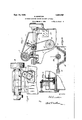
- This invention relates to grinding machines., especially of the. type in which the infeed is accomplished bythe bodily movement of the grinding head towards the work.
- the grinding head is slid-- ably mounted .on a rearwardly extended guideway provided by the bed of the machine.
- Aprimary object of this invention is toeffect a re-design of these parts andto do'so.
- the pulley, the belt, the guideway and the e feed-screw will cooperate to theend that the head will be substantiallybalancedagainst 4 twisting tendencies during the grinding operation.
- Fig-I 4 1s asectionwthrouglifline'l1- 4 of Fig. 1 t0 represent howftlie-tablefmay be -manually traveled by the'user.
- Fig. 5 is a transverse sectlon through-line 5-2-5 .of Fig. 3 showing 1n section a detailof' the power transmission. forunfeedingthe-grindingfhead.
- Fig. ⁇ 6 is a lrear elevation of. the grinding headshowing' lpulljpn the spindlensaid pulley drive emodying an automatic". belt tightener.
- Fig. 8 1s -a sectional' detail thegpumpingsystem for the cooiant. a detail view illus- Yiv man lement ofthe grinder-headfgm e ⁇ andgt e'lafeed screw.
- the 'shaft B ofthe-motor is either connected with or continues leaf shaft liand ⁇ A .the spindle of the grinding-wheel.4
- a small vsprocket-wheel B2 carries the chain 5 which conveys motion to the transmission system for accomplishing the infeed.
- Fig. 7 there is shown in section a portion of the grinding-head C.
- This head being mounted on slidevvays 30 and 31 shown best by Figs. 6 and 9.
- the ,slideway 31 is of the V-type and it (as well as the feed-screw which is coaxial with that slideway) is arranged in balanced relation4 between'the pulley and the grinding wheel as will presently appear.
- a spindle 3 carries a pulley 2 which is located on the opposite side of the V-guide 31 from the grindingwheel 4.
- An idler a is mounted within the grinder-head C and the belt 1 runs fromthe pulley B around this idler a and thence around the pulley 2 so vas to exert a rearward pull on the spindle.
- a belt-tightener takes up the slack of this belt for all of the positions of the grinder-head; this belt tightener consisting of an arm a2 pivoted to the head C at a', and having an idler a5.
- a weight a4 operates through a pull-chain a3 to maintain the idler against the belt and take up its Y slack.
- both the screw and the V-guide l are located in. the midplane between the grinding-wheel and the pulley and the' screw therefore acts as the central fulerum of a balanced lever and the head is corres ondingly relieved from any twisting ten ency.
- the feed-screw is located upon the V-guide in the central plane thereof andconsequently its line' of action is brought quite near to the spindle so that the head is subjected to the minimum amount of overturning force and whateverA overturning force exists is compensated for by the oblique pull of the belt as shown by Fig. 7.
- the chain 5 turns a sprocket-wheel 6 which is appropriately journaled in the bed.
- the shaft of thel sprocket-wheel carries a long pinion 7 which continuously meshes with the' gear 8 of a three-gear cluster adapted to be shifted by a lever L to bring either-one of its gears 8, 9 or 10 into mesh with the respective gears 8, 9 and 10 to impart any one of three different speeds to j shaft 11.
- this causes the worm 12 to rotate and thereby is rotated the worm 13 which actuates an eccentrically mounted roller operating in a slot in the oscillating lever 14.
- oscillations are in turn imparted to an exposed oscillating lever 15 which is provided with a radial slot so that the link 16 may be adjusted thereto to receive a variable throw.
- This link 16 in turn oscillates an'arm 17 which carries a pawl 18 having a catch 19 for engaging the ratchet teeth of a wheel 20.
- a coaxial lever 21 is adjustably fixed to the ratchet-wheel 2() and through intervening gearing which need not be described, accomplishes an intermittent but progressive rotation of the shaft 23 that extends from the front to the rear of the bed.
- a gear train composed of gears 24, 25 and 26 transmit the motion to the shaft 27 which is formed at its forward end into the feed-screw 28 which, in turn, engages the nut 27 that is fixed to the head C so that the head may' thereby be advanced bodily to accomplish the 'soscalled infeed of the grinding-wheel.
- the work represented by W is appropriately mounted on a carriage or work-support S which slides on longitudinal idewa s at the front of the machine.
- A'grinding machine comprising a bed provided with a horizontal guideway; a head translatably supported on said guideway; a spindle journaled in said head; a grindingwheel and a pulley spaced apart on said spindle; a belt-drive exercising a 4rearward pull on said pulley; and a feed-screw arranged substantially midway between said wheel and pulley and substantially in the horizontal and vertical planes of said guideway as to act as a fulcrum and balance the head against twisting under the pull of the belt and the pressupe of the grinding-wheel on its work.
- a grinding machine combining a bed having an upper substantially horizontal surface provided with a V-guide; a head slidably supported on said surface and guided wholly by said V-guide; a bearing in said head arranged in the vertical plane of said V-guide; a spindle rotatably journaled in said bearing; a grinding wheel secured to said spindle at one side of said bearing; a driving ypulley secured to said spindle at the opposite side of said bearing; and means acting in the vertical plane of said V-guide, to translate said head on said guide.
- a grinding machine combining a bed having a rearwardly extending transverse slide-way; a head slidable thereon; a transverse feed-screw located mainly above the bottom of said slideway; a spindle journaled in said head and located somewhat higher thanl v said feed-screw; a grinding-wheel on said spindle at one side of the vertical plane of said screw; and a pulley on said spindle at the opposite side of said plane, the relative distances of said wheel and pulley from said plane being such that the pressure of the grinding-wheel on the work will be substantially balanced by the pull of the belt on said pulley.
- a grinding machine combining a shiftable head; a spindle journaled therein; a grinding-wheel at 'one end of said spindle; a
- a grinding machine having a rearwardly extended V-guide; a feed-screw above the bottom of said V-guide and in the vertical plane thereof; and a grinding-head slidably directed by said V-guide and arranged to be fed by said feed-screw.
- a grinding machine combining a bed having a horizontally disposed slideway and a single angular guideway spaced from said slideway; a head supportedupon said slideway and guideway and held against horizon- -tal rotation by the latter; and a feed-screw located in the vertical plane of and adjacent said guideway and having a threaded engagement with said head.
Landscapes
- Engineering & Computer Science (AREA)
- Mechanical Engineering (AREA)
- Grinding Of Cylindrical And Plane Surfaces (AREA)
- Constituent Portions Of Griding Lathes, Driving, Sensing And Control (AREA)
Description
Spt. 18, 1928. 1,684,792 Y s. EINSTEIN v GRINDING ummm; HAvINGALAncE SPINDLE Filed laren 1, 1924 j 4` sheets-sheet 2 Sept. 18, 1928. Y 1,684,792
Y s. EINSTEIN GRINDINGMACHIN HAVING BALANCE SPINDLE Fneduamn 1.- 1924 4 sheets-sheet Y 5 Sept. 18, 1928. l 1,684,792
, ls. EINSTEIN GRINDING MACHINE HAVING BALANcEu sPmDLg:`
Fqlled larh 1, 1924 4 sneets-sneg't 4 Defeated sepais, 192s.
UNITED. sTATEs RATE-NT oFFicE.
.son Emsrnm, or cmcnmnrr, omo, As'srcivon, BY MESNE "ASSIGNMENTS, To' cINoINNA'rI eamnnas mconronnrnn, orcmcnmnrr omo, A coaroiwrrou cromo. f
This invention relates to grinding machines., especially of the. type in which the infeed is accomplished bythe bodily movement of the grinding head towards the work.
In such machines, the grinding head is slid-- ably mounted .on a rearwardly extended guideway provided by the bed of the machine.
On this guideway is the spindle which car-f ries the grinding wheel and which lalso carries 0 a pulley oran equivalentdevice which re-l ceives the belt that maintains the spindle inv a state of'rotation. When the grinding wheel is'pressed against the work to accomplish its grinding function, there is created 1.5 a tendency to twist the head bodily to a certain extent' and this tendency is, from a standpoint of extreme precision, aggrayated by reason of thevery slight amount of looseness in the slideway of the head and by reason ofthe fact that the pulley. does not inthe conventional design so receive the pull of the belt as to cooperate ltowards reducing the twisting tendency. Furthermore, in conventional machines, the feed-screw is habitually so located as to aggravate vtheaforesaid tende11y,.'l n
Aprimary object of this invention is toeffect a re-design of these parts andto do'so.
in such a manner that the grinding-wheel,
80 the pulley, the belt, the guideway and the e feed-screw will cooperate to theend that the head will be substantiallybalancedagainst 4 twisting tendencies during the grinding operation.
In grinding-machines of (he motor driven` type', the inoto'r has heretofore been located -either in an awkward or unsightly location vv:with respect to the mechanism asa whole, or j elseit has been located inaccessibly. In mo- `40 tor-driven `grinding-machines,l thev general proportions are quite massivev andthe motor isqite large in slze, and -it is important that these l princi al elements be com actly re- "-.lated'not on y1 to save s ace buta so to con- 45. tribute ftowardsv' an or erly appearance.l of lthefniachine as a whole; and it is important r y, that' commutator and the -brushes of the mc to*inay be inspected with facility, other- ,1 V fwise these features which are so consequential '.Wtotheeiiicient operation of the motorare 1 ve likely to become neglected by the user. l(viisher objects and a vantages will be in .indicated .in the following v descriptionthroughout 4'all the views, of which:
certain transmission gears at'the rear thereof. \.F1g. 7 `'isa transverse section through line-f- ,7-7 ,of, Fig.;1"- showing the pulley drive for the spindle arranged .to` exercise arearward `trating theiffre v furnish] Gamme M'Ac'nmn nnvnm Bananen spinnen.
Application med Maron 1,` 19M.v senai-zrafeaaia.
andv in'part rendered apparent therefrom in` connection withthe annexed drawings.
To enable othersskilled in the art so fully to apprehend thaunderl 'ng features hereof that theyV may e body this same in the various ways .contemplated b this v invention, drawings dcpictingla prefe red typical con- 60 struction have been annexed as a part of this ldisclosure and, 'in such-drawings, like characv `ters of reference denote corresponding 'parts Fig. lisa ding-machine in front elevation typifying this invention. Fig. 2isa .transverse section through line 2 2 of Fig. 1 showlng more especially-the transverse slideway for the grinder head and the feed-screw which is locatedto-act as a balance fulcrum.
D gmentary detail in plan ofa portionpolf the lnfeeding mechanism. Fig-I 4 1s asectionwthrouglifline'l1- 4 of Fig. 1 t0 represent howftlie-tablefmay be -manually traveled by the'user. Fig. 5 is a transverse sectlon through-line 5-2-5 .of Fig. 3 showing 1n section a detailof' the power transmission. forunfeedingthe-grindingfhead. Fig.` 6 is a lrear elevation of. the grinding headshowing' lpulljpn the spindlensaid pulley drive emodying an automatic". belt tightener. Fig. 8 1s -a sectional' detail thegpumpingsystem for the cooiant. a detail view illus- Yiv man lement ofthe grinder-headfgm e` andgt e'lafeed screw.
Referringiiov` to 'edrawn'gs, E repre,- sents the bed'of-'t grinding-machine. As shown \1, th rightghand end of the bed i's prouflwed ,u lar eglopenin "into which is'insellbti' ffofthej e ectric motor employed asit mir-fie of ower. `A flange-I'ateA2 provi es-means ,ornbolting V the .motor tothe end of the bedfE and th' motor lprovides an end' casting' whic .the 'bearingjfor its'shaft'fy It` shouldlf;, "noted that lthe lcomunitator endof; ion the motor is exposedthereby providing? irnf mediate access te the @Ommlltatorand 'the brushes while a considerable'portion of the motorie inserted in the end of lthe bed as f shownfv The 'shaft B ofthe-motor is either connected with or continues leaf shaft liand` A .the spindle of the grinding-wheel.4 A small vsprocket-wheel B2 carries the chain 5 which conveys motion to the transmission system for accomplishing the infeed.
Referring now to Fig. 7 ,there is shown in section a portion of the grinding-head C. This head being mounted on slidevvays 30 and 31 shown best by Figs. 6 and 9. The ,slideway 31 is of the V-type and it (as well as the feed-screw which is coaxial with that slideway) is arranged in balanced relation4 between'the pulley and the grinding wheel as will presently appear.
As shown byFig. a spindle 3 carries a pulley 2 which is located on the opposite side of the V-guide 31 from the grindingwheel 4. An idler a is mounted within the grinder-head C and the belt 1 runs fromthe pulley B around this idler a and thence around the pulley 2 so vas to exert a rearward pull on the spindle. A belt-tightener takes up the slack of this belt for all of the positions of the grinder-head; this belt tightener consisting of an arm a2 pivoted to the head C at a', and having an idler a5. A weight a4 operates through a pull-chain a3 to maintain the idler against the belt and take up its Y slack.
By comparing Figs. 1, 2, 6 and 7, it will be seen that the V-guide 31 occupies a position substantially in the central plane between the grinding-wheel 4 and the pulley 2. Consequently, inasmuch as vthe grinding-wheel Vand the pulley are both urged rearwardly with substantially equal forces (the one by the pressure of the work and the other by the pull of the belt) there exists a. state of substantial equilibrium and the head is not subjected to material twisting forces Aand consequently rests truly and easily in its V-guide. There is thus no tendency to cramp and interfere with the infeed of the head and there head is not subjected to any considerable l and 9, is centrally aligned with the V- overturningforces and, by examining Fig. 7 it will be observed that the pull of the belt is such as tends to pull the head down onto its V-guide and to hold it securely in the same.
' he feed-screw 28, as shown by Figs. 6
and consequently its pushdoes notsu ject the grinding-head to any forces tending to ,lift the khead out of said V-guide or to cramp the head against movement in said V-guide.
ide'
Furthermore, both the screw and the V-guide l are located in. the midplane between the grinding-wheel and the pulley and the' screw therefore acts as the central fulerum of a balanced lever and the head is corres ondingly relieved from any twisting ten ency. It is also to be noted that the feed-screw is located upon the V-guide in the central plane thereof andconsequently its line' of action is brought quite near to the spindle so that the head is subjected to the minimum amount of overturning force and whateverA overturning force exists is compensated for by the oblique pull of the belt as shown by Fig. 7.
While various transmission systems may be employed for turning the feed screw, that shown on the drawings is com act and well arranged and may be describe The chain 5 turns a sprocket-wheel 6 which is appropriately journaled in the bed. The shaft of thel sprocket-wheel carries a long pinion 7 which continuously meshes with the' gear 8 of a three-gear cluster adapted to be shifted by a lever L to bring either-one of its gears 8, 9 or 10 into mesh with the respective gears 8, 9 and 10 to impart any one of three different speeds to j shaft 11. As shown by Figs. 3 and 5, this causes the worm 12 to rotate and thereby is rotated the worm 13 which actuates an eccentrically mounted roller operating in a slot in the oscillating lever 14. These oscillations are in turn imparted to an exposed oscillating lever 15 which is provided with a radial slot so that the link 16 may be adjusted thereto to receive a variable throw. This link 16 in turn oscillates an'arm 17 which carries a pawl 18 having a catch 19 for engaging the ratchet teeth of a wheel 20. A coaxial lever 21 is adjustably fixed to the ratchet-wheel 2() and through intervening gearing which need not be described, accomplishes an intermittent but progressive rotation of the shaft 23 that extends from the front to the rear of the bed. A gear train composed of gears 24, 25 and 26 transmit the motion to the shaft 27 which is formed at its forward end into the feed-screw 28 which, in turn, engages the nut 27 that is fixed to the head C so that the head may' thereby be advanced bodily to accomplish the 'soscalled infeed of the grinding-wheel.
The work represented by W is appropriately mounted on a carriage or work-support S which slides on longitudinal idewa s at the front of the machine. The etails o this mechanism need not be described inasmuch as an conventional carriage may be employe for supporting the work; it bein merely noted that-Fig. 4 shows a hand-whee H arranged to turn a pinion h that. engages a rack R for feeding the carriage S. The carconstitute essential characteristics of either.
the generic or specific aspects of this invention, and, therefore, such adaptations should be, and are intended to be, comprehended within the meaning and range of equivalency of the following claims.
Having thus revealed this invention, I claim as new and desire to secure the following combinations and elements', or equivalents thereof, by Letters Patent of the United States 1. A'grinding machine comprising a bed provided with a horizontal guideway; a head translatably supported on said guideway; a spindle journaled in said head; a grindingwheel and a pulley spaced apart on said spindle; a belt-drive exercising a 4rearward pull on said pulley; and a feed-screw arranged substantially midway between said wheel and pulley and substantially in the horizontal and vertical planes of said guideway as to act as a fulcrum and balance the head against twisting under the pull of the belt and the pressupe of the grinding-wheel on its work.
2. A grinding machine combining a bed having an upper substantially horizontal surface provided with a V-guide; a head slidably supported on said surface and guided wholly by said V-guide; a bearing in said head arranged in the vertical plane of said V-guide; a spindle rotatably journaled in said bearing; a grinding wheel secured to said spindle at one side of said bearing; a driving ypulley secured to said spindle at the opposite side of said bearing; and means acting in the vertical plane of said V-guide, to translate said head on said guide. c
3. A grinding machine combining a bed having a rearwardly extending transverse slide-way; a head slidable thereon; a transverse feed-screw located mainly above the bottom of said slideway; a spindle journaled in said head and located somewhat higher thanl v said feed-screw; a grinding-wheel on said spindle at one side of the vertical plane of said screw; and a pulley on said spindle at the opposite side of said plane, the relative distances of said wheel and pulley from said plane being such that the pressure of the grinding-wheel on the work will be substantially balanced by the pull of the belt on said pulley.
4:. A grinding machine combining a shiftable head; a spindle journaled therein; a grinding-wheel at 'one end of said spindle; a
ulley on said spindle; cross-guides for said iiead extending transversely to said spindle substantially in coincidence with a vertical plane transverse to said spindle midway said pulley and said grinding-wheel; and an infeed screw substantially incoincidence with said vertical plane.
5. A grinding machine having a rearwardly extended V-guide; a feed-screw above the bottom of said V-guide and in the vertical plane thereof; and a grinding-head slidably directed by said V-guide and arranged to be fed by said feed-screw.
6. The combination of claim 5 in which a spindle has a bearing in said head in said vertical plane and which carries a grinding-wheel and a pulley on opposite sides of said bearing and at substantially equal distances therefrom. v 4
7. A grinding machine combining a bed having a horizontally disposed slideway and a single angular guideway spaced from said slideway; a head supportedupon said slideway and guideway and held against horizon- -tal rotation by the latter; and a feed-screw located in the vertical plane of and adjacent said guideway and having a threaded engagement with said head.
In witness whereof, .I hereunto subscribe my name.
son EINSTEIN.
Priority Applications (1)
| Application Number | Priority Date | Filing Date | Title |
|---|---|---|---|
| US696196A US1684792A (en) | 1924-03-01 | 1924-03-01 | Grinding machine having balanced spindle |
Applications Claiming Priority (1)
| Application Number | Priority Date | Filing Date | Title |
|---|---|---|---|
| US696196A US1684792A (en) | 1924-03-01 | 1924-03-01 | Grinding machine having balanced spindle |
Publications (1)
| Publication Number | Publication Date |
|---|---|
| US1684792A true US1684792A (en) | 1928-09-18 |
Family
ID=24796087
Family Applications (1)
| Application Number | Title | Priority Date | Filing Date |
|---|---|---|---|
| US696196A Expired - Lifetime US1684792A (en) | 1924-03-01 | 1924-03-01 | Grinding machine having balanced spindle |
Country Status (1)
| Country | Link |
|---|---|
| US (1) | US1684792A (en) |
-
1924
- 1924-03-01 US US696196A patent/US1684792A/en not_active Expired - Lifetime
Similar Documents
| Publication | Publication Date | Title |
|---|---|---|
| US1684792A (en) | Grinding machine having balanced spindle | |
| US2121080A (en) | Sewing machine belt drive | |
| US1909832A (en) | Saw grinding machine | |
| US2375789A (en) | Milling machine attachment for lathes | |
| US2029385A (en) | Machine tool | |
| US1147214A (en) | Attachment for grinding-machines. | |
| GB657086A (en) | Improvements in grinding machines | |
| US1924593A (en) | Grinding machine | |
| US1736967A (en) | Grinding machine | |
| US2170901A (en) | Buffing machine | |
| USRE16196E (en) | A cobpobation | |
| US1268961A (en) | Grinding-machine. | |
| US2326661A (en) | Truing apparatus | |
| US1952966A (en) | Automatic lathe with automatically slidable headstock | |
| US1424764A (en) | Surface grinder | |
| US1447383A (en) | Wheel-dressing mechanism | |
| US1842306A (en) | Tailor's chalk sharpener | |
| US1991953A (en) | Grinding machine | |
| US596503A (en) | harper | |
| US845687A (en) | Cutting and grinding machine. | |
| US1749328A (en) | Dead-center grinder | |
| US1701675A (en) | Precision thread-grinding machine | |
| US1515620A (en) | Drilling and routing machine | |
| US1814431A (en) | Grinding machinery | |
| US2569618A (en) | Winding machine |