US1675813A - Grease-melting furnace - Google Patents
Grease-melting furnace Download PDFInfo
- Publication number
- US1675813A US1675813A US97672A US9767226A US1675813A US 1675813 A US1675813 A US 1675813A US 97672 A US97672 A US 97672A US 9767226 A US9767226 A US 9767226A US 1675813 A US1675813 A US 1675813A
- Authority
- US
- United States
- Prior art keywords
- grease
- pot
- shaft
- furnace
- opening
- Prior art date
- Legal status (The legal status is an assumption and is not a legal conclusion. Google has not performed a legal analysis and makes no representation as to the accuracy of the status listed.)
- Expired - Lifetime
Links
- 238000002844 melting Methods 0.000 title description 6
- 239000004519 grease Substances 0.000 description 27
- 230000008018 melting Effects 0.000 description 5
- 238000003756 stirring Methods 0.000 description 5
- 238000002156 mixing Methods 0.000 description 4
- 238000002485 combustion reaction Methods 0.000 description 2
- 239000007789 gas Substances 0.000 description 2
- ATJFFYVFTNAWJD-UHFFFAOYSA-N Tin Chemical compound [Sn] ATJFFYVFTNAWJD-UHFFFAOYSA-N 0.000 description 1
- 239000003245 coal Substances 0.000 description 1
- 239000000571 coke Substances 0.000 description 1
- 230000003247 decreasing effect Effects 0.000 description 1
- 238000007599 discharging Methods 0.000 description 1
- 239000000446 fuel Substances 0.000 description 1
- 239000007788 liquid Substances 0.000 description 1
- 230000001050 lubricating effect Effects 0.000 description 1
- 238000012986 modification Methods 0.000 description 1
- 230000004048 modification Effects 0.000 description 1
- 210000003739 neck Anatomy 0.000 description 1
- 239000004449 solid propellant Substances 0.000 description 1
- 239000005028 tinplate Substances 0.000 description 1
- 238000007514 turning Methods 0.000 description 1
Images


Classifications
-
- C—CHEMISTRY; METALLURGY
- C11—ANIMAL OR VEGETABLE OILS, FATS, FATTY SUBSTANCES OR WAXES; FATTY ACIDS THEREFROM; DETERGENTS; CANDLES
- C11B—PRODUCING, e.g. BY PRESSING RAW MATERIALS OR BY EXTRACTION FROM WASTE MATERIALS, REFINING OR PRESERVING FATS, FATTY SUBSTANCES, e.g. LANOLIN, FATTY OILS OR WAXES; ESSENTIAL OILS; PERFUMES
- C11B1/00—Production of fats or fatty oils from raw materials
- C11B1/12—Production of fats or fatty oils from raw materials by melting out
Definitions
- This invention relates to furnaces and more particularly to grease mcltmg furnaces for melting the. grease-used tolubricate the necks'of the hot rolls in a tinmill, andghas for'its object theprovis'ion of a novel form of furnace which will melt the grease in much less time than the furnaces heretofore used and which will prevent the burning of the grease.
- the present invention provides. a motor driven rotary pot,having bafiles for stirring and mixing the grease and, therefore, overcomes all the objections to the old style pot, and in addition the furnace and pot of this invention will melt the grease in much less time than the apparatus heretofore used.
- Figure 1 is a plan View of a furnace embodying our invention.
- Figure 2 is an end elevation thereof.
- Figure 3 is an elevation of the end opposite that shown in Figure 2.
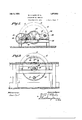
- Figure 4 is a transverse sectional view taken on line IVIV of Figure 5.
- Figure 5 is a longitudinal sectional view taken on the line VV of Figure 1.
- the letter A designates the enclosing structure or housing of the furnace as a whole, which is composed of end walls 2 and 3, side walls 4 and 5, and an arched roof or top Wall 6.
- a fire box-7 is provided at one end of the furnace housing and is provided with grates 8 for supporting a coal fire.
- grates 8 for supporting a coal fire.
- any other form of gaseous, liquid, or solid fuel maybe used, and the fire box 7 may be altered to accommodate such fuels without departing from our invention.
- a stack flue 9 is formed at the bottom of the other end of the furnace housing A and communicates with a stack (not shown).
- a hollow shaft 10 passes through the fur- .nace and is journaled in bearings 11 and 12 supported on the end walls of the fur.
- the shaft 10 is PI'OVldEClWlth vent openings 18 and19 within the pot 13 to permit the escapeof vapors or gases from the pot during the melting of the grease.
- a pair of baffle plates 20 and 21 extend longitudinally in the pct 13 and are secured to the pot and adapted to mix and stir the grease when the pot is rotated. That is, they will carry the grease up as the pot is rotated and then permit it to drop into the melted grease, thus turning, mixing and stirring the same.
- the shaft 10 and pct 13 are rotated by an electric motor 24 which is mounted on motor shelf 25 and has its armature shaft provided with a pulley 26.
- the pulley 26 is connected by a belt 27 to a pulley 28 on a shaft 29, which shaft has a pinion 30 meshed with a gear 31 on a shaft 32.
- the shaft 32 is provided with a pinion 33 which meshes with a gear 34 on the hollow shaft 10.
- a baffle wall 35 extends upwardly from the bottom of the furnace, intermediate its ends, to approximately the center line of the pot 13, and is adapted to cause the products of combustion to pass upwardly from the fire box 7 around one end, then along the pot 13 and down around the other end thereof to the stack flue 9, thus causing an even heat along the entire pot.
- the furnace will be fired and the pot 13 will be charged with cold heavy grease through the opening 14 After the pot has been charged the opening 14 will 'be closed by the door 15 and the motor 24 will be started to rotate the pot l3.
- the bafiie members and 21 will continually carry the grease upwardly and let it drop backinto the pot, thus mixing and stirring the grease.
- bafiie wall willcause the products of combustion to be distributed over the entire surface of the pot and thereby heat and melt the entire charge of grease.
- a grease melting furnace comprising an enclosing structure, a hollow shaft extending through said structure, a closed frusto-conical grease pot secured on said shaft and rota-table therewith.
- said pot having a gradually decreasing diameter toward one end, said enclosing structure being provided with an'opening in one end to expose the larger circular end of said pot, an inlet opening in said exposed larger circular end of said pot, a closure for said inlet opening, avalved outlet in said exposed larger end of said pot ata point therein substantially din-metrically opposite. from said shaft'and rotatable therewith, means for 1-0-1 tating said shaft and said.
- said shaft having itsends open to the atmosphere and being provided with at least one vent opening adjacent one end wall of the pot and intermediate its ends communicating with the interior of said pot at a point adjacent one end of said pot to ip'ermitthe gases generated in saidpot to escape through said shaft, and a cylindrical hood member secured to the end wall of said pot adjacent said vent opening and projecting outwardly around said shaft beyond said "out opening to prevent grease from falling from the side wa ls of said pot into said vent opening and clogging said opening during the rotation of.
Landscapes
- Chemical & Material Sciences (AREA)
- Life Sciences & Earth Sciences (AREA)
- Engineering & Computer Science (AREA)
- Chemical Kinetics & Catalysis (AREA)
- Oil, Petroleum & Natural Gas (AREA)
- Wood Science & Technology (AREA)
- Organic Chemistry (AREA)
- Vertical, Hearth, Or Arc Furnaces (AREA)
Description
July 3, 1928.
W. C. LOYD ET AL GREASE MELTING FURNACE Filed March 26, 1926 4 Sheets-Sheet &
Vdb'nesses:
3% o W Z n; 22. m W Z July 3, 1928.
w. c. LQYD ET AL GREASE IMIIJLTING FURNACE Filed March 26, 1926 4 Sheets-Sheet 4 Tr it i Q w Witnesses: 8: Z N gfi jmentars: v V
Patented July 3, 1928. 1
UNITED TAT PATENT OFFICE,
WILLIAM 0510?]: AND ARTHUR a. Mc RTHUajoE GARY, iNEIANA, AssmNoas 1'0 AMERICAN SHEET ND TIN PLATE COMPANY, or PITTSBURGH, PENNSYLVANIA,
A CORPORATION OF NEW JERSEY.
GBEASE-MELTI NG FURNACE.
Application filed March 26, 1926, Serial No. 97,672.
This invention relates to furnaces and more particularly to grease mcltmg furnaces for melting the. grease-used tolubricate the necks'of the hot rolls in a tinmill, andghas for'its object theprovis'ion of a novel form of furnace which will melt the grease in much less time than the furnaces heretofore used and which will prevent the burning of the grease. 1 l
'Heretofore pets for melting and. mixing the grease used tolubricatethe HBOkSgOf the hot rolls in tin mills have. consisted of a sta tionary pot or pan of about 12'feet wide, 14 feet longand 3feetdeep, built over a furnace and have the. entire top open for filling and stirring with a hand paddle. These pots required a great amount of manual labor, and the fact that heat does not travel well through heavy grease caused the grease to become overheated atthe bottom, which formed coke and materially lessened the lubricating qualities of the grease.
The present invention provides. a motor driven rotary pot,having bafiles for stirring and mixing the grease and, therefore, overcomes all the objections to the old style pot, and in addition the furnace and pot of this invention will melt the grease in much less time than the apparatus heretofore used.
In the drawings:
Figure 1 is a plan View of a furnace embodying our invention.
Figure 2 is an end elevation thereof.
Figure 3 is an elevation of the end opposite that shown in Figure 2.
Figure 4 is a transverse sectional view taken on line IVIV of Figure 5.
Figure 5 is a longitudinal sectional view taken on the line VV of Figure 1.
.Referring more particularly to the drawings, the letter A designates the enclosing structure or housing of the furnace as a whole, which is composed of end walls 2 and 3, side walls 4 and 5, and an arched roof or top Wall 6.,
A fire box-7 is provided at one end of the furnace housing and is provided with grates 8 for supporting a coal fire. However, it will be understood that any other form of gaseous, liquid, or solid fuel maybe used, and the fire box 7 may be altered to accommodate such fuels without departing from our invention.-
A stack flue 9 is formed at the bottom of the other end of the furnace housing A and communicates with a stack (not shown).
A hollow shaft 10 passes through the fur- .nace and is journaled in bearings 11 and 12 supported on the end walls of the fur.
nace.-, Acylindrical grease pot 13 having bearlugs 14 and 15 :at its opposite ends, is secured on the shaft 10 so as to rotate therc- 1 with, The end wall 3 of the furnace housmg ,ISOPGII so as to expose the head end of the pot 13, which end is provided with an inlet or charging opening 14. normally closed by a hinged closure or door 15?, and an outlet opening 16 for the discharge of. the melted grease, which opening is conand discharging end toward the other end so that the-inelted grease will flow toward the headend of the Pot.
The shaft 10 is PI'OVldEClWlth vent openings 18 and19 within the pot 13 to permit the escapeof vapors or gases from the pot during the melting of the grease.
A pair of baffle plates 20 and 21 extend longitudinally in the pct 13 and are secured to the pot and adapted to mix and stir the grease when the pot is rotated. That is, they will carry the grease up as the pot is rotated and then permit it to drop into the melted grease, thus turning, mixing and stirring the same.
The shaft 10 and pct 13 are rotated by an electric motor 24 which is mounted on motor shelf 25 and has its armature shaft provided with a pulley 26. The pulley 26 is connected by a belt 27 to a pulley 28 on a shaft 29, which shaft has a pinion 30 meshed with a gear 31 on a shaft 32. The shaft 32 is provided with a pinion 33 which meshes with a gear 34 on the hollow shaft 10.
A baffle wall 35 extends upwardly from the bottom of the furnace, intermediate its ends, to approximately the center line of the pot 13, and is adapted to cause the products of combustion to pass upwardly from the fire box 7 around one end, then along the pot 13 and down around the other end thereof to the stack flue 9, thus causing an even heat along the entire pot.
In operation the furnace will be fired and the pot 13 will be charged with cold heavy grease through the opening 14 After the pot has been charged the opening 14 will 'be closed by the door 15 and the motor 24 will be started to rotate the pot l3.
the pot 13 is rotated the bafiie members and 21 will continually carry the grease upwardly and let it drop backinto the pot, thus mixing and stirring the grease.
The bafiie wall willcause the products of combustion to be distributed over the entire surface of the pot and thereby heat and melt the entire charge of grease.
After the grease is melted the motor 24 will be stopped and the melted grease will be drawn from the pot through the valve 17. 7
While we have shown one specific embodiment of our invention, it will be understood that we do not wish to be limited thereto since various modifications may be made without departin from the scope of our invention as definet in the appended claims. "Ve claim: g
1. A grease melting furnace comprising an enclosing structure, a hollow shaft extending through said structure, a closed frusto-conical grease pot secured on said shaft and rota-table therewith. said pot having a gradually decreasing diameter toward one end, said enclosing structure being provided with an'opening in one end to expose the larger circular end of said pot, an inlet opening in said exposed larger circular end of said pot, a closure for said inlet opening, avalved outlet in said exposed larger end of said pot ata point therein substantially din-metrically opposite. from said shaft'and rotatable therewith, means for 1-0-1 tating said shaft and said. pot, said shaft having itsends open to the atmosphere and being provided with at least one vent opening adjacent one end wall of the pot and intermediate its ends communicating with the interior of said pot at a point adjacent one end of said pot to ip'ermitthe gases generated in saidpot to escape through said shaft, and a cylindrical hood member secured to the end wall of said pot adjacent said vent opening and projecting outwardly around said shaft beyond said "out opening to prevent grease from falling from the side wa ls of said pot into said vent opening and clogging said opening during the rotation of.
said pot.
In testimony whereof,- set our hands.
WILLIAM ChLOYDQ ARTHUR R. MOARTI'IUR.
we have hereunto
Priority Applications (1)
| Application Number | Priority Date | Filing Date | Title |
|---|---|---|---|
| US97672A US1675813A (en) | 1926-03-26 | 1926-03-26 | Grease-melting furnace |
Applications Claiming Priority (1)
| Application Number | Priority Date | Filing Date | Title |
|---|---|---|---|
| US97672A US1675813A (en) | 1926-03-26 | 1926-03-26 | Grease-melting furnace |
Publications (1)
| Publication Number | Publication Date |
|---|---|
| US1675813A true US1675813A (en) | 1928-07-03 |
Family
ID=22264566
Family Applications (1)
| Application Number | Title | Priority Date | Filing Date |
|---|---|---|---|
| US97672A Expired - Lifetime US1675813A (en) | 1926-03-26 | 1926-03-26 | Grease-melting furnace |
Country Status (1)
| Country | Link |
|---|---|
| US (1) | US1675813A (en) |
-
1926
- 1926-03-26 US US97672A patent/US1675813A/en not_active Expired - Lifetime
Similar Documents
| Publication | Publication Date | Title |
|---|---|---|
| US792642A (en) | Melting-furnace. | |
| US2035282A (en) | Furnace construction | |
| US1675813A (en) | Grease-melting furnace | |
| US1415061A (en) | Furnace-retort | |
| US2043459A (en) | Sewage disposal apparatus | |
| US1446863A (en) | Gypsum calcining apparatus | |
| US1171583A (en) | Ore-roasting apparatus. | |
| US1830002A (en) | Apparatus for roasting material | |
| GB191023430A (en) | Improvements in Tilting Calcining or Roasting Furnaces. | |
| US492551A (en) | Furnace for roasting | |
| US181776A (en) | Improvement in apparatus for desulphurizing ores | |
| US2112401A (en) | Apparatus for coking solid fuel briquettes | |
| US1213347A (en) | Retort apparatus. | |
| US1852646A (en) | Furnace for dewatering and the like | |
| US1058342A (en) | Apparatus for preparing paving material. | |
| US792169A (en) | Rotary furnace. | |
| CH182329A (en) | Firing for solid, fine-grain fuels. | |
| US1387780A (en) | Melting-pot | |
| US1339544A (en) | Treating zinc oxid | |
| SU14535A1 (en) | Rotary Melting Furnace | |
| US169047A (en) | Improvement in puddling-furnaces | |
| US1415201A (en) | Furnace-retort | |
| DE596282C (en) | Device for melting down particles of easily oxidizable light metal, e.g. B. aluminum | |
| US1045528A (en) | Melting-furnace. | |
| US1213346A (en) | Retort apparatus. |