US1664097A - Protective device - Google Patents
Protective device Download PDFInfo
- Publication number
- US1664097A US1664097A US1664097DA US1664097A US 1664097 A US1664097 A US 1664097A US 1664097D A US1664097D A US 1664097DA US 1664097 A US1664097 A US 1664097A
- Authority
- US
- United States
- Prior art keywords
- connection
- electroresponsive
- rotatable member
- circuit
- movement
- Prior art date
- Legal status (The legal status is an assumption and is not a legal conclusion. Google has not performed a legal analysis and makes no representation as to the accuracy of the status listed.)
- Expired - Lifetime
Links
- 230000001681 protective effect Effects 0.000 title description 4
- 230000001276 controlling effect Effects 0.000 description 32
- 238000007689 inspection Methods 0.000 description 5
- 238000009877 rendering Methods 0.000 description 5
- 230000000694 effects Effects 0.000 description 4
- 238000004804 winding Methods 0.000 description 4
- 230000002159 abnormal effect Effects 0.000 description 3
- 230000002093 peripheral effect Effects 0.000 description 3
- 230000004043 responsiveness Effects 0.000 description 3
- 230000003247 decreasing effect Effects 0.000 description 2
- 230000003111 delayed effect Effects 0.000 description 2
- XAGFODPZIPBFFR-UHFFFAOYSA-N aluminium Chemical compound [Al] XAGFODPZIPBFFR-UHFFFAOYSA-N 0.000 description 1
- 229910052782 aluminium Inorganic materials 0.000 description 1
- 230000001419 dependent effect Effects 0.000 description 1
- 238000009413 insulation Methods 0.000 description 1
- 239000012212 insulator Substances 0.000 description 1
- 238000012986 modification Methods 0.000 description 1
- 230000004048 modification Effects 0.000 description 1
- 230000000135 prohibitive effect Effects 0.000 description 1
- 230000004044 response Effects 0.000 description 1
- 230000035945 sensitivity Effects 0.000 description 1
- 230000035939 shock Effects 0.000 description 1
Images
Classifications
-
- H—ELECTRICITY
- H01—ELECTRIC ELEMENTS
- H01H—ELECTRIC SWITCHES; RELAYS; SELECTORS; EMERGENCY PROTECTIVE DEVICES
- H01H71/00—Details of the protective switches or relays covered by groups H01H73/00 - H01H83/00
Definitions
- M invention relates to im rovements'in protective devices and particu arly to relays for the protection of high voltage electric circuits upon the occurrence. of abnormal conditions, such as excess current.
- Circuit interrupters are usually controlled by relays or trip coils operative in response to abnormal circuitconditions and in the protection of alternating current circuits, the relays or trip coils are often connected to the secondaries of current transformers, which may also supply c'urrentto meters and instruments or may be of'special design for circuit interrupter" control only. When, however, the cost of current transformers is prohibitive because of the high voltage of the circuit to be protected, some other satisfactory but more economical arrangement must be employed.
- the energizing windings of the relays may, or course, be connected dircctly in the linecircuit, but as thissubjects the relays to line potential, the risk involvcd in inspections, tests and adjustments, particularly with the usual type of relay and especially with the line circuit alive, is very undesirable and can be avoided only by interruption of line service, which also is very undesirable. It is therefore essential to isolate the necessarily high voltage parts of the relay from the low voltage parts such as the contact controlling mechanism and also to provide personal safety for inspections and adjustments while the line circuit is alive. I
- the motion transmitting mechanism should require only a small operating force and for safety should have high insulating properties.
- the motion transmitting mechanism should not be affected by air currents, inherent changes in length such as those due to changes in humidity, stretch, shrinkage and the like to an extent sufficient to affect either theadjustment or reliability of operation of the relay,
- An object of my invention is therefore to provide an improved electroresponsive devic'e'or relay particularly adapted for use on' high voltage alternating current circuits without-the necessity of employing current transformers, although its use is not so limitedfsu'ch thatfreliability of operation and facility of adjustment and inspection with a maximum of personal safety is assured.
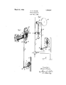
- FIG. 1 illustrates in perspective an embodiment of my invention
- Fig. 2 illustrates diagrammatically an application of the embodiment of my invention shown in Fig. 1.
- my invention comprises electroresponsive means 1 operative upon the occurrence of an abnormal circuit condition, such as excess or over-current, to control a constant controlling mechanism 2, spaced at a safe distance dependent upon the voltage of the circuit 3 to be protected, through a motion transmitting mechanism comprising a rotatable member 4 and suitable connections 5 and 6 between said member and both the contact controlling mechanism 2 and a movable member, such as the armature 7 of the electroresponsive means 1, whereby motion can be transmitted from one to the other.
- an abnormal circuit condition such as excess or over-current
- the electroresponsive means 1 is adapted for mounting on a suitably supported insulator 8 and comprises an energizing winding9 adapted for direct connection in the circuit '3 to be protected.
- any well known by-pass arrangement may be used such as a resistor by-pass 10 connected across the winding 9 for high ampere capacities or a spark gap by-pass for low ampere capacities.
- the contact controlling mechanism 2 is mounted on a suitable support 11 so as to be conveniently accessible for inspection and adjustment and comprises relatively movable cooperating contacts 12 and 13 which may be arranged to control a circuit 14 connected to a control bus 15 and including the trip coil lG of suitable circuit interrupting means, such as a circuit breaker 17 which is connected in the circuit 3 to be protected.
- this mechanism comprises .a: movable. member,
- Thebellows device 21 Thebellows device 21.
- connectionli may be, forexa'mple, a chain arranged -to cngageteeth-on the cylindrical. portion .22.
- The-connectionG is Earranged to engage a-igr'oove in the-cylindrical portion 23 1 and I; have :founda %that a. paper cord impregn ated with a suitable insulatingcompound has --not only; excellent: insulating,
- connection 5. is secured to and engages the jcylindrical portion .22 of the rotatable member l so as to be on one side thereof and the other end is "secured to the armature 7.
- One end of the connecally tion 6 is secured to and engages the cylindrical portion 23 so as to be on the opposite side of: the rotatable member 4: and the other end is secured to a suitable biasing means comprising a weight 24 carried by a pivotmoimtedmember or arm 25 which is pivotally-related to the operating rod 18 of the contact controlling mechanism.
- the movableparts are so balanced by suitably .proportion iug the weights and lever arms thereof that upon energization of the armature 7,.sutlicient .to move itfrom its initial position, the sileight 24 fallsand in sodoing effects the movement of the contacts 12 and 13 .to circuit. controlling position.
- the armature 'Z may be rovidedwith aIbiasing member such as a :welght; 26, which may..be, for..-example, of.
- connection 6 is preferably provided with a shock absorbing means; suchasa spring 27. located intermediate the rotatablemember 4 :and the weight 24 so as to reduce the effect of-shocks attendant .upon su dden movements .ofthe armature 7.
- a shock absorbing means such as a spring 27. located intermediate the rotatablemember 4 :and the weight 24 so as to reduce the effect of-shocks attendant .upon su dden movements .ofthe armature 7.
- the spring 27.- maybe. located adjacent the rotatableimember. 4 and may be,,housed in a casingr28 cit-small. weights Asuitably supported guide; 29' through which. the connection- 6 can :fireely move may. also be :provided.
- the rotatablepmember 4 carries. a conspicuous graduated: gsca-le preferably. on the cylindrical portionz23t .which can be conveniently .readzat ae-distance to ascertain the settingornesponsiveness ofrthe relay, one
- theweight 24 is preferably provided with a helical. groove .inwhich the-lower endof the connection 6. is woumland a clamping screw 31-is provided for holding the weight 24 in any desiredposition so that the length offlthe conneetionfiimaybe changed-as de sired. This.
- I preferably make the diameter of the cylindrical portion 23 of the rotatahle member 4 relatively large as compared with the diameter of the cylindrical portion 22 so that for any change in length of the connection 6 the corresponding change in length of the connection 5 will be very small, since the changes in the free lengths of the connections will be proportional. to the diameters of the respective cylindrical portions.
- circuit controlling mechanism In a device of the class described, circuit controlling mechanism, electroresponsive means spaced therefrom for controlling the operation thereof, a flexible insulating connection between said mechanism and said electroresponsive means, and means Whereby the control of said mechanism by said electroresponsive means is rendered substantially independent of inherent changes in the length of said connection.
- circuit controlling mechanism electroresponsive means spaced therefrom for controlling the operation thereof comprising a member adapted to be moved from an initial position, a flexible connection between said mechanism and said member subject to change in length with variations in humidity, means for minimizing the movement of said member from initial position due to changes in the length of said connection caused by variations in humidity, and means associated with said mechanism and adapted to be operated to change the initial position of said member.
- circuit controlling mechanism electroresponsive means spaced therefrom for controlling the operation thereof comprising a movable member, a rotatable member comprising a plurality of cylindrical portions of relatively large and small diameters, a flexible connection between said movable member and said small diameter cylindrical portion arranged for peripheral engagement. therewith, and-a flexible connection between said circuit controlling mechanism and said large diameter cylindrical portion arranged for peripheral engagement therewith.”
- cir cuit controlling mechanism electroresponsive means spaced therefrom for controlling the'operation thereof comprising a movable member, a rotatable member comprising a plurality 'of cylindrical portions of relatively large and small diameters, flexible connections between both said circuit con trolling mechanism and said movable memher and said rotatable member arranged for peripheral engagement with the cylindrical portions thereof so that upon movement of said movable member the free length of one in, of said connections is decreased and the free length of the other connection increased by amounts proportional to the diameters of the respective cylindrical portions.
- high H5 tension electroresponsive means comprising a rotatable member, an electroresponsive member arranged upon deenergization thereof to turn said rotatable member in one direction and upon energization thereof" to permit 12o movement of said rotatable member in the opposite direction, and low tension circuit.
- controlling mechanism comprising relatively movable cooperating contacts, biasing means and a fiexibleinsulating connection between said rotatable member and said biasing means arranged to turn said rotatal'ile memher in said opposite direction upon energization of said electroresponsive member whereby to efi'ect the movement of said contacts ill to circuit controlling position and means for rendering .the control. of-said mechanism by said electroresponsive member substantially independent of inherent changes in the length of said connection.
- high tension electroresponsive means comprising a. rotatable member, an electroresponsive n'iember arranged upon deenergization thereof to turn-said rotatable member in one di-- rection and upon energization thereof-to permit movement of Stlitl rotatable member in the. oposite direction, and low *iZCDSlOIl circuitcontrolling mechanism comprising rel-.
- high tension electroresponsive means comprising a and-:1 flexible insulating connection-betweensaid rotatable member and said biasing .mcans arranged to turn'said rotatable member in said opposite direction upon energization of said elec'iroresponsive member whereby to etiect the movement of said contacts to circuit controlling position, means associated with said rotatable member for rendering the control of said mechanism by-said electroresprms-ive member substantially independent oi inherent changes in the length of said connection and means for limiting the movement o't said rotatable member -.in said one direction.
- high tension electroresponsi-ve means comprising a rotatable member, an electroresponsive member arianged'upon decnergization thereof to turn said rotatable member in one-direction :andupon energization thereof to permit movement oi' said rotatable member in the opposite direction
- low-tension circuit controlling mechanism comprising relatively .movable cooperating contacts, biasing means and a flexible insulating: connection between said rotatable member and said biasing means arranged to turn said rotatable member inasaid' opposite direction upon energization of said eleetroresponsive member whereby to etfectr the movement of said contacts tocircuitcontrollingposition, means associated with said rotatable member for-rendering the control of saidaneehanismby said electroresponsive member substantially independent of inherent changes in the length of..s-aid' connection, means-for limiting the.
- -high tension electroresponsive:means comprising a rotatable tmember, an-electroresponsive member arranged upon deenergization thereof to turnsaid rotatablermember in one direction land :upon energization thereofi to permit movement of.
- said :rotatable member in the opposite ldirection and low -tension circuit controlling mechanism comprising relatively -movaible cooperating contacts, biasing--meansiand a flexible insulating connection between; said rotatable member and saidbiasing means arranged to turn said rotatable member in said opposite direction uponenergizati'on of said elect-roresponsive member whereby to effect the movement of said contacts to circuit cont-rolling position, means associated with said rotatable member for-rendering.
- the control-of said mechanism bysaid electroresponsive member substantially independent of inherent changes in the lengtlrof said connection, means for limiting.
Landscapes
- Breakers (AREA)
Description
March 27, 19221 I 1,664,097
0. C. TRAVER PROTECTIVE DEVICE Filed Feb. 1. 1924 Inventor O/iver C. Fan er,
His Attorngy Patented Mar. 27, 1928.
UNITED STATES PATENT OFFICE.
OLIVER C. TRAVER, F SCHENECTADY, NEW YORK, ASSIGNOR TO GENERAL ELECTRIC COMPANY, A CORPORATION OIE NEW YORK.
PROTECTIVE DEVICE.
Application filed February 1, 1924. Serial No. 690,098.
M invention relates to im rovements'in protective devices and particu arly to relays for the protection of high voltage electric circuits upon the occurrence. of abnormal conditions, such as excess current.
Circuit interrupters are usually controlled by relays or trip coils operative in response to abnormal circuitconditions and in the protection of alternating current circuits, the relays or trip coils are often connected to the secondaries of current transformers, which may also supply c'urrentto meters and instruments or may be of'special design for circuit interrupter" control only. When, however, the cost of current transformers is prohibitive because of the high voltage of the circuit to be protected, some other satisfactory but more economical arrangement must be employed. The energizing windings of the relays may, or course, be connected dircctly in the linecircuit, but as thissubjects the relays to line potential, the risk involvcd in inspections, tests and adjustments, particularly with the usual type of relay and especially with the line circuit alive, is very undesirable and can be avoided only by interruption of line service, which also is very undesirable. It is therefore essential to isolate the necessarily high voltage parts of the relay from the low voltage parts such as the contact controlling mechanism and also to provide personal safety for inspections and adjustments while the line circuit is alive. I
There is thus introduced a space factor which involves a mechanism for transmitting motion between the high and low voltage parts of the relay whereby motion of the movable member of the high voltage part can be transmitted to the contact controlling mechanism for operation thereof and viceversa for adjusting the sensitivity of the relay to different predetermined conditions. Moreover,- in order to avoid excessive size of relay structure and not appreciably affect the responsiveness of the relay, the motion transmitting mechanism should require only a small operating force and for safety should have high insulating properties. Furthermore, the motion transmitting mechanism should not be affected by air currents, inherent changes in length such as those due to changes in humidity, stretch, shrinkage and the like to an extent sufficient to affect either theadjustment or reliability of operation of the relay,
An object of my invention is therefore to provide an improved electroresponsive devic'e'or relay particularly adapted for use on' high voltage alternating current circuits without-the necessity of employing current transformers, although its use is not so limitedfsu'ch thatfreliability of operation and facility of adjustment and inspection with a maximum of personal safety is assured.
My invention will be better understood from the following description taken in connection with the'accompanying drawing and its scope will be pointed out in the appended claims.
Fig. 1 illustrates in perspective an embodiment of my invention and Fig. 2 illustrates diagrammatically an application of the embodiment of my invention shown in Fig. 1.
In general, my invention comprises electroresponsive means 1 operative upon the occurrence of an abnormal circuit condition, such as excess or over-current, to control a constant controlling mechanism 2, spaced at a safe distance dependent upon the voltage of the circuit 3 to be protected, through a motion transmitting mechanism comprising a rotatable member 4 and suitable connections 5 and 6 between said member and both the contact controlling mechanism 2 and a movable member, such as the armature 7 of the electroresponsive means 1, whereby motion can be transmitted from one to the other.
The electroresponsive means 1 is adapted for mounting on a suitably supported insulator 8 and comprises an energizing winding9 adapted for direct connection in the circuit '3 to be protected. In order to prevent high frequency surges from breaking down the insulation of the winding 9, any well known by-pass arrangement may be used such as a resistor by-pass 10 connected across the winding 9 for high ampere capacities or a spark gap by-pass for low ampere capacities.
The contact controlling mechanism 2 is mounted on a suitable support 11 so as to be conveniently accessible for inspection and adjustment and comprises relatively movable cooperating contacts 12 and 13 which may be arranged to control a circuit 14 connected to a control bus 15 and including the trip coil lG of suitable circuit interrupting means, such as a circuit breaker 17 which is connected in the circuit 3 to be protected.
It may-be desirable to have the movement of the contacts 12 and= 13--'tooircuitcon--- trolling position either substantially instantaneous or time delayed and for these pur-' poses, I may use a mechanism .of the type disclosed in my LettersPatent of the Unit'ed States, No. 1,5.32,Q03,-d ated March 31,1325,-
. forzrelay device assigned to the same assignee as this invention. In general this mechanism comprises .a: movable. member,
such aswainoperating rod. 18..whichjupon movement in .one .directionhis arranged to.
. .st ness spring 19 carried in= a.casin g 20 which issecured .to a. suitable bellolws device 2 1,- suclr that ,the energy. stored :in. the spring 19 is slowly ,dissipated. :and the movement goithe.mo vable contact 13 :carriedgby the casing .20 therebydelayed. Thebellows device 21.
isdetachable as a unitzfrom the easing'20 so that the .contact controlling; mechanism may be'quickly. and-easily converted from time delayed to sl'ibstantially. instantaneous operation. v
,F or. transmitting.,movement from the armature 7 to-the contact controlling means 2, I preferably prov idethe, rotatable, member is increased and the free length of the other connection decreased by-..amounts proportional to. the diameters. of .the irespective cylindrical portions which they engage. The connectionli may be, forexa'mple, a chain arranged -to cngageteeth-on the cylindrical. portion .22. The-connectionG is Earranged to engage a-igr'oove in the-cylindrical portion 23 1 and I; have :founda %that a. paper cord impregn ated with a suitable insulatingcompound has --not only; excellent: insulating,
properties but .is .also subject -to:.only slight;
changes in length dueto variations -in humidity.
One end of the connection 5.is secured to and engages the jcylindrical portion .22 of the rotatable member l so as to be on one side thereof and the other end is "secured to the armature 7. One end of the connecally tion 6 is secured to and engages the cylindrical portion 23 so as to be on the opposite side of: the rotatable member 4: and the other end is secured to a suitable biasing means comprising a weight 24 carried by a pivotmoimtedmember or arm 25 which is pivotally-related to the operating rod 18 of the contact controlling mechanism. The movableparts are so balanced by suitably .proportion iug the weights and lever arms thereof that upon energization of the armature 7,.sutlicient .to move itfrom its initial position, the sileight 24 fallsand in sodoing effects the movement of the contacts 12 and 13 .to circuit. controlling position. Upon energization .of..the.winding 9 below a predetermined .value,..the.armature 7 returns to its initial position resetting'thecontact controlling mechanism i. F or. balancing purposes, thearmature 'Zmay be rovidedwith aIbiasing member such as a :welght; 26, which may..be, for..-example, of. aluminum and is meferablyspheroidal so: as to .actas an electirostaticshield The connection 6 is preferably provided with a shock absorbing means; suchasa spring 27. located intermediate the rotatablemember 4 :and the weight 24 so as to reduce the effect of-shocks attendant .upon su dden movements .ofthe armature 7. I The spring 27.- maybe. located adjacent the rotatableimember. 4 and may be,,housed in a casingr28 cit-small. weights Asuitably supported guide; 29' through which. the connection- 6 can :fireely move may. also be :provided.
- The rotatablepmember 4 carries. a conspicuous graduated: gsca-le preferably. on the cylindrical portionz23t .which can be conveniently .readzat ae-distance to ascertain the settingornesponsiveness ofrthe relay, one
of the guide supports 30 serving as an indexor. pointer, .ln-rorder that .the position of the.armaturev7, t-hataisto say,.-the pick-up point 'or sensitiveness of the-relay can be changedsconveniently. and without personal risk when the circuit of the relay is alive, theweight 24 is preferably provided with a helical. groove .inwhich the-lower endof the connection 6. is woumland a clamping screw 31-is provided for holding the weight 24 in any desiredposition so that the length offlthe conneetionfiimaybe changed-as de sired. This. adjusting .means together with the: conspicuously .-visualscale; thus affords a-.ma:imum ofi-personal'safety.trom the line voltage when-inspections and adjustments are necessary .-While it is possible-to obtain a suitable insillating.materiiil-.-.for the connection 6 such that variationsin humidity change the length of the connection only slightly, nevertheless it isdesirable to minimize the efiectof these slight changes on.' the position of the armature 7, that is to say,.the sensitivencss of the relay, so as 'to .re nderthe controlof the contact controlling mechanism substantially independent of variations in humidity. For this purpose, I preferably make the diameter of the cylindrical portion 23 of the rotatahle member 4 relatively large as compared with the diameter of the cylindrical portion 22 so that for any change in length of the connection 6 the corresponding change in length of the connection 5 will be very small, since the changes in the free lengths of the connections will be proportional. to the diameters of the respective cylindrical portions. lVIoreover, since the connection (3 is relatively light in weight, it possesses relatively little inertia and, since it presents but small surface to the air there is substantially no tendency for air currents to affect the adjustment of the relay. Furthermore, drift or sway of the connection (1 due to air currents cannot affect operation of the contact controlling mechanism because of the counterbalanced arrangement of the movable parts and also because such drift tends to pull downward on the operat- Q ing rod 18 and downward movement thereof is prevented by suitable means such as a stop 32- which establishes, for a given free length of the connection (3, the initial position of the armature 7. In addition, the flexibility of the connection (3 affords considerable latitudc inthe. arrangement of the contact controlling mechanism with respect to the electroresponsive means '1. For example, in a practical en'iboiliment of my invention the maximum inclination from the vertical of the connection (3 is about fifteen degrees and as the length of the connection 6 would be in practice relatively large, a wide range for positioning the contact controlling mechanism is available.
While I have shown and described only one embodimentof my invention, I do not desire to be limited to the exact arrangement shown and described but'seek to cover in the appended claims all those modifications that fall w thin the true spirit and scope of my invention.
\Vhat I claim as new and desire to secure by Letters Patent of the United States, iS2-- 1. In a device of the class described, circuit controlling mechanism, clectroresponsive means spaced therefrom for control.-
ling the operation thereof comprising a member adapted to be moved from an initial position, a connection between said mechanism and said member, and means for minin'iizing the movement of said member from initial position due to inherent changes in the length of said connection.
In a device of the class described, circuit controlling mechanism, electroresponsive means spaced therefrom for controlling the operation thereof, a flexible insulating connection between said mechanism and said electroresponsive means, and means Whereby the control of said mechanism by said electroresponsive means is rendered substantially independent of inherent changes in the length of said connection.
3. In a device of the class described, circuit controlling mechanism, electroresponsive means spaced therefrom for controlling the operation thereof comprising a member adapted to be moved from an initial position, a flexible connection between said mechanism and said member subject to change in length with variations in humidity, means for minimizing the movement of said member from initial position due to changes in the length of said connection caused by variations in humidity, and means associated with said mechanism and adapted to be operated to change the initial position of said member.
4. In a device of the class described, circuit controlling mechanism, electroresponsive means spaced therefrom for controlling the operation thereof comprising a movable member, a rotatable member comprising a plurality of cylindrical portions of relatively large and small diameters, a flexible connection between said movable member and said small diameter cylindrical portion arranged for peripheral engagement. therewith, and-a flexible connection between said circuit controlling mechanism and said large diameter cylindrical portion arranged for peripheral engagement therewith." r
5. In a device of the class described, cir cuit controlling mechanism, electroresponsive means spaced therefrom for controlling the'operation thereof comprising a movable member, a rotatable member comprising a plurality 'of cylindrical portions of relatively large and small diameters, flexible connections between both said circuit con trolling mechanism and said movable memher and said rotatable member arranged for peripheral engagement with the cylindrical portions thereof so that upon movement of said movable member the free length of one in, of said connections is decreased and the free length of the other connection increased by amounts proportional to the diameters of the respective cylindrical portions.
6. In a device of the class described, high H5 tension electroresponsive means comprising a rotatable member, an electroresponsive member arranged upon deenergization thereof to turn said rotatable member in one direction and upon energization thereof" to permit 12o movement of said rotatable member in the opposite direction, and low tension circuit. controlling mechanism comprising relatively movable cooperating contacts, biasing means and a fiexibleinsulating connection between said rotatable member and said biasing means arranged to turn said rotatal'ile memher in said opposite direction upon energization of said electroresponsive member whereby to efi'ect the movement of said contacts ill to circuit controlling position and means for rendering .the control. of-said mechanism by said electroresponsive member substantially independent of inherent changes in the length of said connection.
7. In a device of the class described, high tension electroresponsive means comprising a. rotatable member, an electroresponsive n'iember arranged upon deenergization thereof to turn-said rotatable member in one di-- rection and upon energization thereof-to permit movement of Stlitl rotatable member in the. oposite direction, and low *iZCDSlOIl circuitcontrolling mechanism comprising rel-.
ati-vel movable r00 )eratin contactsbiasing means and a flexible insulating eonnec--- tion between said rotatable member and said biasing means arranged to turn said -lOi';&ttl-- ble member m said-opposite (iH'QCt-lOILUPOII euergization of said electroresponsive member whereby to effect the movement of said contacts to circuit controllingposition, means for rendering -the control of-saidmechanism bysaid electroresponsive member substantially independent. of inherent changes :in the length of said connection, and rr-neans for delaying the movement of said contacts to circuit controlling position.
8.111 a device of the class described, high tension electroresponsive means comprising a and-:1 flexible insulating connection-betweensaid rotatable member and said biasing .mcans arranged to turn'said rotatable member in said opposite direction upon energization of said elec'iroresponsive member whereby to etiect the movement of said contacts to circuit controlling position, means associated with said rotatable member for rendering the control of said mechanism by-said electroresprms-ive member substantially independent oi inherent changes in the length of said connection and means for limiting the movement o't said rotatable member -.in said one direction.
9. In a deviceoi' the class described, high tension electroresponsi-ve means comprising a rotatable member, an electroresponsive member arianged'upon decnergization thereof to turn said rotatable member in one-direction :andupon energization thereof to permit movement oi' said rotatable member in the opposite direction, and low-tension circuit controlling mechanism comprising relatively .movable cooperating contacts, biasing means and a flexible insulating: connection between said rotatable member and said biasing means arranged to turn said rotatable member inasaid' opposite direction upon energization of said eleetroresponsive member whereby to etfectr the movement of said contacts tocircuitcontrollingposition, means associated with said rotatable member for-rendering the control of saidaneehanismby said electroresponsive member substantially independent of inherent changes in the length of..s-aid' connection, means-for limiting the. movement of said rotatable member in said one direction, and means adapted to be operated? to: change the extent of movement of said-electroresponsive member whereby the position assumed thereby upon deenerg-ization thereof can beavaried so as to vary the responsivenessrof said electroresponsivemeans.
10. In a device of the class described,-high tension electroresponsive:means comprising a rotatable tmember, an-electroresponsive member arranged upon deenergization thereof to turnsaid rotatablermember in one direction land :upon energization thereofi to permit movement of. said :rotatable member in the opposite ldirection and low -tension circuit controlling mechanism comprising relatively -movaible cooperating contacts, biasing--meansiand a flexible insulating connection between; said rotatable member and saidbiasing means arranged to turn said rotatable member in said opposite direction uponenergizati'on of said elect-roresponsive member whereby to effect the movement of said contacts to circuit cont-rolling position, means associated with said rotatable member for-rendering. the control-of said mechanism bysaid electroresponsive member substantially independent of inherent changes in the lengtlrof said connection, means for limiting. the movement of said rotatable member in said one direction, means adapted to be operated to change the extent of movement of said electroresponsive member whereby the position assumed thereby upon deenergization thereof can be varied so as to vary the responsiveness of said electroresponsiveimeans, and means associated with said rotatable member for indicating the responsiveness of said electroresponsive means forithe respective positions of said electroresponsive member.
In witness whereof, Lhave hereunto setmy hand this 30th day of January, 1924.
OLIVER C. TRAVER.
Publications (1)
| Publication Number | Publication Date |
|---|---|
| US1664097A true US1664097A (en) | 1928-03-27 |
Family
ID=3414792
Family Applications (1)
| Application Number | Title | Priority Date | Filing Date |
|---|---|---|---|
| US1664097D Expired - Lifetime US1664097A (en) | Protective device |
Country Status (1)
| Country | Link |
|---|---|
| US (1) | US1664097A (en) |
-
0
- US US1664097D patent/US1664097A/en not_active Expired - Lifetime
Similar Documents
| Publication | Publication Date | Title |
|---|---|---|
| US1664097A (en) | Protective device | |
| US1940300A (en) | Circuit breaker | |
| US2495127A (en) | Three-stage retarded electromagnetic device | |
| US3227925A (en) | Control for switch means | |
| US1852614A (en) | Flashover relay | |
| US2142188A (en) | Protective bushing for electrical apparatus | |
| US1194132A (en) | Time-limit belay | |
| US1217469A (en) | Time-element relay. | |
| US2217406A (en) | Voltage regulator | |
| US796646A (en) | Time-limit circuit-controller. | |
| US2594107A (en) | Quiet overload circuit breaker | |
| US1278966A (en) | Circuit-interrupter. | |
| US1280661A (en) | Electromagnetic switch. | |
| US3109962A (en) | Time-delay devices | |
| US2077212A (en) | Contact making voltmeter | |
| US1873950A (en) | Electrical relay | |
| US1815861A (en) | Protective apparatus | |
| US1714940A (en) | Protective apparatus | |
| US1433712A (en) | Circuit-interrupting device | |
| US2598463A (en) | Time element electromagnetic device | |
| US1740465A (en) | Relay device | |
| US1501733A (en) | Relay | |
| US2246306A (en) | Regulator | |
| US2351945A (en) | Circuit controlling apparatus | |
| US1344196A (en) | Electromotive device |