US1663991A - Centerless work guide - Google Patents
Centerless work guide Download PDFInfo
- Publication number
- US1663991A US1663991A US195409A US19540927A US1663991A US 1663991 A US1663991 A US 1663991A US 195409 A US195409 A US 195409A US 19540927 A US19540927 A US 19540927A US 1663991 A US1663991 A US 1663991A
- Authority
- US
- United States
- Prior art keywords
- work
- rock
- shafts
- guide
- guides
- Prior art date
- Legal status (The legal status is an assumption and is not a legal conclusion. Google has not performed a legal analysis and makes no representation as to the accuracy of the status listed.)
- Expired - Lifetime
Links
- 239000011435 rock Substances 0.000 description 18
- 230000001105 regulatory effect Effects 0.000 description 6
- 210000005069 ears Anatomy 0.000 description 4
- 230000001276 controlling effect Effects 0.000 description 3
- 230000007246 mechanism Effects 0.000 description 3
- RTZKZFJDLAIYFH-UHFFFAOYSA-N Diethyl ether Chemical compound CCOCC RTZKZFJDLAIYFH-UHFFFAOYSA-N 0.000 description 2
- 230000009471 action Effects 0.000 description 2
- 238000010276 construction Methods 0.000 description 2
- 238000004519 manufacturing process Methods 0.000 description 2
- 230000000717 retained effect Effects 0.000 description 2
- 238000000926 separation method Methods 0.000 description 2
- 229910001347 Stellite Inorganic materials 0.000 description 1
- AHICWQREWHDHHF-UHFFFAOYSA-N chromium;cobalt;iron;manganese;methane;molybdenum;nickel;silicon;tungsten Chemical compound C.[Si].[Cr].[Mn].[Fe].[Co].[Ni].[Mo].[W] AHICWQREWHDHHF-UHFFFAOYSA-N 0.000 description 1
- 230000001419 dependent effect Effects 0.000 description 1
- 238000006073 displacement reaction Methods 0.000 description 1
- 230000007775 late Effects 0.000 description 1
- 230000004048 modification Effects 0.000 description 1
- 238000012986 modification Methods 0.000 description 1
- 229920000136 polysorbate Polymers 0.000 description 1
- 108010085990 projectin Proteins 0.000 description 1
- 230000000630 rising effect Effects 0.000 description 1
- 230000000153 supplemental effect Effects 0.000 description 1
Images
Classifications
-
- B—PERFORMING OPERATIONS; TRANSPORTING
- B24—GRINDING; POLISHING
- B24B—MACHINES, DEVICES, OR PROCESSES FOR GRINDING OR POLISHING; DRESSING OR CONDITIONING OF ABRADING SURFACES; FEEDING OF GRINDING, POLISHING, OR LAPPING AGENTS
- B24B5/00—Machines or devices designed for grinding surfaces of revolution on work, including those which also grind adjacent plane surfaces; Accessories therefor
- B24B5/18—Machines or devices designed for grinding surfaces of revolution on work, including those which also grind adjacent plane surfaces; Accessories therefor involving centreless means for supporting, guiding, floating or rotating work
- B24B5/307—Means for supporting work
Definitions
- GUIDE CENTERLESS wom
- This invention relates to improvements in centerless grinding machinery and more particularly to the mechanism for controlling the ingress and egress of the work pieces in connection with such machines;
- Centerless grinders as now recognized in the art, comprise a pair of opposed wheels, one for grinding or operating upon the work and the other for regulating the movements of the work in thel machine, together with an intermediate work rest for supporting the Work in operative position.
- Such machines are used in the production of automobile parts and other structures of circular form in cross section in which extreme accuracy, as for example,- one or two tenthousandths of an inch is required.
- An essential for the production of work accurate to this degree is that the work pieces be guided into exact correct position with respect to the 'grinding throat at the entrant side and also that they be properly guided after they emerge from the machine.
- One of the objects ofI the present invention is the provision of a novel and improved structure of guide mechanisms for use in connection with suchl grinders which may be readily adjusted with extreme accuracy to properly align the surfaces of the guides with the operative surfaces of the wheels and prevent twisting or displacement of the Work piece.
- a further object of the invention is the provision of a guide mechanism capable of a Wide range of adjustment to care for work varying from a fractional part of an inch to work of several inches in diameter.
- An additional object of the invention is the provision of means for rigidly holding the guides against twisting movement out of parallelism with the plane of the work rest.
- Figure 1 is aside elevation of a centerless grinder with the present improvements applied thereto.
- Figure 2 is a fragmentary vertical sectional view on the linel 2 2 of Figure 1.
- Figure 3 is a transverse section on line 3-3 of Figure 2.
- Figure 4 is a vertical section on line 4-4 of F1gure 3.
- FIG. 5 is a similar view Iillustrating the adjlustment for larger diameter work pieces, an
- Figure 6 is a fragmentary horizontal section on the line 6-6 of Figure 2.
- the letter A designates thev bed of a centerless grinder on which is rotatably supported the grinding wheel B
- the bed in addition is formed with Ways C for main slide D bearin supplemental slide E for the regulating w eel F which is rigidly or adjustably mounted with its axis at an ⁇ angle to the axis of the grinding wheel so that the regulating wheel will exert a lateral thrust or feed component tending to move the work pieces axially through the
- These parts constitute the commercial Cincinnati centerless grinder and as so known do not require further detailed description.
- the wheels B and F form therebeL tween as at point 15 a grinding throat adapted to receive a work leoe or series of work pieces at 16.
- a grinding throat adapted to receive a work leoe or series of work pieces at 16.
- the slide D is provided with a seat 17 for the work rest-supporting block 18 which has suitably secured thereto and extending thereabove the stellite or other hardened work rest 19 having a beveled upper edge 20 supporting the work piece 16.
- the slide D makes it possible to laterally adjust this work rest with rei spect to the grinding wheel for work of different diameters 'as will be apparent by comparison of . Figures 4 and 5.
- the manner of mounting of the work rest facilitates interchangement of work rests of different heights according to .the diameter of workbeing operated upon'and the vertical position in the throat at which it is desired to have the contact points 21 and 22 between the work and-the engaging wheels.
- block 18 has the laterally extending perforate ears 23-24 and 25-26 arran ed 1n-pairs at the entrant side of the mac ine and a corresponding set at th ⁇ e exit sideof the machine.
- these sets are dup- O licates one (of the other the arrangement at one end onlyof the machine will be speciically descr1bed.
- J ournaled in the ears 23- 24 is a rock-shaft 28 and in the ears 25-26 a second rock-shaft 29,l these being accurately machined to have'their axes extending in plane parallel to each other land. to the intermedlate plane of work rest 19.
- Screws 31-35 have tapered heads tending to draw the face plates against their respective guide plates while screws 31-'35" are of the lillister-head type and are supported on beveled upper ends of the guide plates so that they exert a tendency both to draw the face plate backward against the guide plate and in addition to press it downward into tight engagement With screws 31-35.
- the block 18 is formed with bracket-lugs and 45 respectively receiving the adjusting screws 46 and 47 for contact with the free i ends of arms 41 and 43. Adjustment of these set screws will depress the free ends of the arms rocking the guideplates inward, while relieving the downward pressure on said arms allows the springY 39 to rock'the guides in a reverse or opening direction.
- pins 51 each having a taper recess 52 to recelve the taper end 53 of lock screw 54.
- Loosening of the screw without withdrawal from recess 52 will freethe pin lsuiiiciently to permit removal of the work rest while on the contrary tightening of screw 54- will cause its end 53 to wedge against the inclined wall of recess 52 forcing in 51 back ⁇ into clamping engagement with t e rest.
- This device maybe advantageously employed for securing the central portion of the work rest and preventing lateral -or springing movement while the outer end may be held by an ordinar clamp screw 55.
- a centerless grinder the combination with a bed, of a grinding wheel supported thereby, a slide on the bed, a regulating wheel mounted on the slide for adjustment with and relative 4to the slide, a support carried by the slide and disposed intermediate the grinding and regulating wheels, a-work rest intermediately mounted on the support, a pair of rock shafts carried by the support at opposite sides of the work rest and ex'-, tending parallel therewith, guides on the rock shafts projecting upwardly' above the work rest, individual means for rocking the p shafts in one direction to vary the position ofthe guides carried thereby and means for jointly urging the shafts in the opposite direction against the action of the individual adjusting means therefor.
- a work rest member for'fa centerless grinder including a support, a work rest plate intermediatel mounted .on the support, rock shafts lateral y spaced from said'work rest plate, guides on the shafts, and members for securing the guides to their shafts, said members having exteriorly projecting portions for actuating the shafts to separate the guide members.
- a work rest member for a centerless A grinder including a support, a work rest plate intermediatel mounted on the support,
- Awvork rest member for a centerless grinder including a support, a work restl plate intermediately mounted on the support, rock shafts laterally spaced from said work rest plate, guides on the shafts, and members securing the parts to ether, said members having exteriorly projectin tions, meansv jointly acting upon sai projecting portions for actuating the shafts to separate the guide members, rock arms on the shafts, and means engaging the individual rock arms for var lng the position of the arms and thus of t e guides carried by' their respective rock shafts.
- a work guiding and supporting device'for a centerless grinder including a supportmg block, work guides laterally pivoted to the block for in and out swinging movement, resilient means for jointly outwardly i urging the guide plates, and means terminally secured to the block and operatively l associated with the guide plates for individually inwardly shiftin said uide plates.
- a work guiding device r a centerless grinder including a sup orting block, uide plates laterally pivoted to the bloc in spaced opposed pairs and capable of wide angle ⁇ of movement relative to the supporting block, individual control arms operatively associated with the guide plates and exteriorly disposed with respect thereto, and means for engaging said arms to individually 'vary the position ⁇ of the guide plates, said adjustin arms being of less-lengt than the length o the plates, whereby a limited movement of the arms will produce a wide variation in ⁇ position of the operative portion of thev guide lates.
- a work gui mg device for a centeri less grinder com rising a-main Supporting block work g'uidb plates laterally pivoted to the block, rock shafts individually secured to said plates, ⁇ over-lapping control arms carried by the' rock shafts and disposed adjacent one tothe other, and adjusting devices mounted on the support for engagement with the arms to vary the position of their guide plates.
- a work guiding device for a centerless grinder comprising a main supporting block, work guidev plates laterall pivote to the block, rock shafts Vindivi ually secured to said plates, over-lappin control arms carried by the rock vshafts an disposed adjacent one to the other and adjusting devices mounted on the support forren'gagement with the arms to vary th'e position of a their guide plates, said adjustln devices being disposed on the opposite si e of the support from the rock shaft controlled thereby, whereby maximum rangel of ad- ⁇ mNyIsi ature.
Landscapes
- Engineering & Computer Science (AREA)
- Mechanical Engineering (AREA)
- Grinding Of Cylindrical And Plane Surfaces (AREA)
Description
March 279 .'I L F. NENNENGER CENTERLESS WORK GUIDE Filed May 51. 1927 `2 sheets-sheet l IM/wankel abbo/mau March 27, 1928.- 1,663,991'
' L. F. NENNINGER CENTERLESS WORK GUIDE Filed May .'51. 1927 2 Sheets-Sheet 2 35% MMM 61H0: ne 1,1
Patented Mar. 27, 192.8.`
UNITED STATES PATENT OFFICE.
LESTER F. NENNINGER, OF CINCINNATI, OHIO, ASSIGNOR TO CINCINNATI GRINDERS INCORPORATED, OF CINCINNATI,
OHIO, A CORPORATION OF OHIO.
CENTERLESS wom: GUIDE.
Application led Hay 31,
This invention relates to improvements in centerless grinding machinery and more particularly to the mechanism for controlling the ingress and egress of the work pieces in connection with such machines;
Centerless grinders as now recognized in the art, comprise a pair of opposed wheels, one for grinding or operating upon the work and the other for regulating the movements of the work in thel machine, together with an intermediate work rest for supporting the Work in operative position. Such machines are used in the production of automobile parts and other structures of circular form in cross section in which extreme accuracy, as for example,- one or two tenthousandths of an inch is required. An essential for the production of work accurate to this degree is that the work pieces be guided into exact correct position with respect to the 'grinding throat at the entrant side and also that they be properly guided after they emerge from the machine.
Slight deflections in the entrant or emergent guides will cause corresponding deflections in the work pieces with a consequent grinding-off action at their enrls producing tapered or inaccurate work.'
One of the objects ofI the present invention,'therefore', is the provision of a novel and improved structure of guide mechanisms for use in connection with suchl grinders which may be readily adjusted with extreme accuracy to properly align the surfaces of the guides with the operative surfaces of the wheels and prevent twisting or displacement of the Work piece.
A further object of the invention is the provision of a guide mechanism capable of a Wide range of adjustment to care for work varying from a fractional part of an inch to work of several inches in diameter.
An additional object of the invention is the provision of means for rigidly holding the guides against twisting movement out of parallelism with the plane of the work rest.
Other objects and advantages of the present invention should be readily apparent by reference to thefollowing speciiication taken in connection with the accompanying drawings and it will be understood that any modifications in the specific details of construction falling within the scope of the -appended claims may be made without demachine.
1927. Serial No. 195,408.
parting from or exceeding the spirit of the invention.
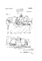
Figure 1 is aside elevation of a centerless grinder with the present improvements applied thereto. v f
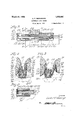
Figure 2 is a fragmentary vertical sectional view on the linel 2 2 of Figure 1.
Figure 3 is a transverse section on line 3-3 of Figure 2.
Figure 4 is a vertical section on line 4-4 of F1gure 3.
Figure 5 is a similar view Iillustrating the adjlustment for larger diameter work pieces, an
Figure 6 is a fragmentary horizontal section on the line 6-6 of Figure 2.
In the 'drawings the letter A designates thev bed of a centerless grinder on which is rotatably supported the grinding wheel B The bed in addition is formed with Ways C for main slide D bearin supplemental slide E for the regulating w eel Fwhich is rigidly or adjustably mounted with its axis at an `angle to the axis of the grinding wheel so that the regulating wheel will exert a lateral thrust or feed component tending to move the work pieces axially through the These parts constitute the commercial Cincinnati centerless grinder and as so known do not require further detailed description.
The wheels B and F form therebeL tween as at point 15 a grinding throat adapted to receive a work leoe or series of work pieces at 16. As prevlously mentioned the important feature lis that these work pieces be supported in exact alignment with the grinding throat prior to their introduction into the machine by guides lightly but accurately engaging the work piece and so spaced as to receive the rough blank, and that in addition guides having a `definite adjustment be provided at the opposite side so that they will properly engage and maintain in correct axial position the emergent work piece of a reduced diameter. To accomplish these results the slide D is provided with a seat 17 for the work rest-supporting block 18 which has suitably secured thereto and extending thereabove the stellite or other hardened work rest 19 having a beveled upper edge 20 supporting the work piece 16. The slide D makes it possible to laterally adjust this work rest with rei spect to the grinding wheel for work of different diameters 'as will be apparent by comparison of .Figures 4 and 5. At the same time the manner of mounting of the work rest facilitates interchangement of work rests of different heights according to .the diameter of workbeing operated upon'and the vertical position in the throat at which it is desired to have the contact points 21 and 22 between the work and-the engaging wheels.
In addition block 18 has the laterally extending perforate ears 23-24 and 25-26 arran ed 1n-pairs at the entrant side of the mac ine and a corresponding set at th`e exit sideof the machine. As these sets are dup- O licates one (of the other the arrangement at one end onlyof the machine will be speciically descr1bed. J ournaled in the ears 23- 24 is a rock-shaft 28 and in the ears 25-26 a second rock-shaft 29,l these being accurately machined to have'their axes extending in plane parallel to each other land. to the intermedlate plane of work rest 19. Secured upon rock-shaft 28 intermediate its supporting ears is guide 30 extending upward above the maximum height of the Work rest, surface 20 and having removably retained on its face as by screws v31--31 the hardened face plate 32 for engagement with the work piece'. Rock-shaft 29 similarly bears guide plate 33' having the facing 34 removably retained by screws 35-35. Attention 1s invited to the fact that` this attachment is made by beveling off the edges vof the hardened facing so that it is unnecessary to drill same. Screws 31-35 have tapered heads tending to draw the face plates against their respective guide plates while screws 31-'35" are of the lillister-head type and are supported on beveled upper ends of the guide plates so that they exert a tendency both to draw the face plate backward against the guide plate and in addition to press it downward into tight engagement With screws 31-35.
To secure the guide plates against rotation relative to the supporting rock-shafts therefor; use is made of the taper pins 36' having the depending portions 37 formed with grooves 38 to receive the ends of spring 39. This spring, therefore, exerts a. tension tending to swing the guide plates apart or into positionJ of maximum separation and exerts an .equal or balanced pressure against two plates so that both can be adjusted at any time with equal facility and without undue pressure against either due tothe general variance in position of one or the other of the guide plates. To accomplish such adjustment, rock-shaft 28 has secured thereto hub 40 of rock arm 4l while shaft 29 bears hub 42 of rock arm 43, the two arms being disposed in overlapping relation as most clearly illustrated in Figures 3 and 6.
To control the position o the two rockarms and thus of the guide members, the block 18 is formed with bracket-lugs and 45 respectively receiving the adjusting screws 46 and 47 for contact with the free i ends of arms 41 and 43. Adjustment of these set screws will depress the free ends of the arms rocking the guideplates inward, while relieving the downward pressure on said arms allows the springY 39 to rock'the guides in a reverse or opening direction.'y
It will be noted that the work rest 19 is shown as supported in recess 50 of block 18,
being suitably and removably secured as by the pins 51 each having a taper recess 52 to recelve the taper end 53 of lock screw 54. Loosening of the screw without withdrawal from recess 52 will freethe pin lsuiiiciently to permit removal of the work rest while on the contrary tightening of screw 54- will cause its end 53 to wedge against the inclined wall of recess 52 forcing in 51 back `into clamping engagement with t e rest.
This device maybe advantageously employed for securing the central portion of the work rest and preventing lateral -or springing movement while the outer end may be held by an ordinar clamp screw 55. This permits of a readi y interchangement and replacement of the work rest proper by placing the controlling means therefor, like the controlling means forthe guide adjustment, at a point exteriorly of the grinding throat and accessible without separation of the wheels or variation in position of the Work supporting block and slide.
From the foregoing description the structural details of the guide members and their manner of adjustment should be readily understood and it will be noted that there has been provided a' construction in which the work rest and guide members as an enlos tirety are carried by a supporting block v which is laterally adjustable through movement of the main slide D, while the several guides are themselves each individually adjust-able through variance in position of an individual adjusting screw enga ing the arm of the guide plate rock shaft. n this manner each of the four main guide plates may be individuallyadjusted into exact correct relationship to the operative face of the adjacent work engaging wheel dependent on the diameter of the work piece being guided i means for rocking the shafts to vary the position of the guides with respect to the Work rest.
2. In a centerless grinder the combination with a bed, of a grinding wheel supported thereby, a slide on the bed, a regulating wheel mounted on the slide for adjustment with and relative 4to the slide, a support carried by the slide and disposed intermediate the grinding and regulating wheels, a-work rest intermediately mounted on the support, a pair of rock shafts carried by the support at opposite sides of the work rest and ex'-, tending parallel therewith, guides on the rock shafts projecting upwardly' above the work rest, individual means for rocking the p shafts in one direction to vary the position ofthe guides carried thereby and means for jointly urging the shafts in the opposite direction against the action of the individual adjusting means therefor.
3. A work rest member for'fa centerless grinder including a support, a work rest plate intermediatel mounted .on the support, rock shafts lateral y spaced from said'work rest plate, guides on the shafts, and members for securing the guides to their shafts, said members having exteriorly projecting portions for actuating the shafts to separate the guide members. L
4. A work rest member for a centerless A grinder including a support, a work rest plate intermediatel mounted on the support,
rock shafts lateral y spaced "from said work rest plate, guides on the shafts',- members :for
securing the guides to their shafts, said.
members having exteriorly projecting portions, means jointly engaging said projecting portions Ifor actuating thevshafts to se arate the guide members, and means for in ividually rocking the shafts to move the guide members inwardly. Y
5. Awvork rest member for a centerless grinder including a support, a work restl plate intermediately mounted on the support, rock shafts laterally spaced from said work rest plate, guides on the shafts, and members securing the parts to ether, said members having exteriorly projectin tions, meansv jointly acting upon sai projecting portions for actuating the shafts to separate the guide members, rock arms on the shafts, and means engaging the individual rock arms for var lng the position of the arms and thus of t e guides carried by' their respective rock shafts.
- 6. In a centerless grinder the combination with opposed grindin and regulating wheels forming a wor J reiving throat therebetween, of a supportxlisposed' intermediate said wheels havin a work rest portion projecting into the grlnding throat and having a pluralit of rock shafts disposed exteriorly of sai throat,A certain of said per- 8. A work guiding and supporting device'for a centerless grinder including a suportmg block, work guides laterally pivoted to the block for in and out swinging movement, resilient means for jointly outwardly i urging the guide plates, and means terminally secured to the block and operatively l associated with the guide plates for individually inwardly shiftin said uide plates.
9. A work guiding device r a centerless grinder including a sup orting block, uide plates laterally pivoted to the bloc in spaced opposed pairs and capable of wide angle `of movement relative to the supporting block, individual control arms operatively associated with the guide plates and exteriorly disposed with respect thereto, and means for engaging said arms to individually 'vary the position` of the guide plates, said adjustin arms being of less-lengt than the length o the plates, whereby a limited movement of the arms will produce a wide variation in` position of the operative portion of thev guide lates. v
10. A work gui mg device for a centeri less grinder com rising a-main Supporting block, work g'uidb plates laterally pivoted to the block, rock shafts individually secured to said plates,` over-lapping control arms carried by the' rock shafts and disposed adjacent one tothe other, and adjusting devices mounted on the support for engagement with the arms to vary the position of their guide plates.
11. A work guiding device for a centerless grinder comprising a main supporting block, work guidev plates laterall pivote to the block, rock shafts Vindivi ually secured to said plates, over-lappin control arms carried by the rock vshafts an disposed adjacent one to the other and adjusting devices mounted on the support forren'gagement with the arms to vary th'e position of a their guide plates, said adjustln devices being disposed on the opposite si e of the support from the rock shaft controlled thereby, whereby maximum rangel of ad-` mNyIsi ature. L STER F. NEN N
Priority Applications (1)
| Application Number | Priority Date | Filing Date | Title |
|---|---|---|---|
| US195409A US1663991A (en) | 1927-05-31 | 1927-05-31 | Centerless work guide |
Applications Claiming Priority (1)
| Application Number | Priority Date | Filing Date | Title |
|---|---|---|---|
| US195409A US1663991A (en) | 1927-05-31 | 1927-05-31 | Centerless work guide |
Publications (1)
| Publication Number | Publication Date |
|---|---|
| US1663991A true US1663991A (en) | 1928-03-27 |
Family
ID=22721312
Family Applications (1)
| Application Number | Title | Priority Date | Filing Date |
|---|---|---|---|
| US195409A Expired - Lifetime US1663991A (en) | 1927-05-31 | 1927-05-31 | Centerless work guide |
Country Status (1)
| Country | Link |
|---|---|
| US (1) | US1663991A (en) |
Cited By (2)
| Publication number | Priority date | Publication date | Assignee | Title |
|---|---|---|---|---|
| US4930260A (en) * | 1987-11-18 | 1990-06-05 | Akebono Brake Industry Co., Ltd. | Centerless grinding apparatus of through-feed type |
| US20150298275A1 (en) * | 2012-12-14 | 2015-10-22 | Erwin Junker Grinding Technology A.S. | Method and cylindrical grinding machine for centerless cylindrical grinding |
-
1927
- 1927-05-31 US US195409A patent/US1663991A/en not_active Expired - Lifetime
Cited By (3)
| Publication number | Priority date | Publication date | Assignee | Title |
|---|---|---|---|---|
| US4930260A (en) * | 1987-11-18 | 1990-06-05 | Akebono Brake Industry Co., Ltd. | Centerless grinding apparatus of through-feed type |
| US20150298275A1 (en) * | 2012-12-14 | 2015-10-22 | Erwin Junker Grinding Technology A.S. | Method and cylindrical grinding machine for centerless cylindrical grinding |
| US11383342B2 (en) * | 2012-12-14 | 2022-07-12 | Erwin Junker Grinding Technology A.S. | Method and cylindrical grinding machine for centerless cylindrical grinding |
Similar Documents
| Publication | Publication Date | Title |
|---|---|---|
| US1663991A (en) | Centerless work guide | |
| US2694322A (en) | Threading appliance | |
| US1483748A (en) | Grinding machine | |
| US1814367A (en) | Long bar grinder | |
| US2304580A (en) | Grinding machine | |
| US2246023A (en) | Grinding machine | |
| US1585984A (en) | Grinding | |
| US1638028A (en) | Grinding machine | |
| US2619997A (en) | Jointer and planer | |
| US1871504A (en) | Truing device for the wheels of grinding machines | |
| US2345986A (en) | Cutter manufacture | |
| US2213756A (en) | Grinding machine | |
| GB553594A (en) | Improvements in or relating to the formation of a profile on an article in a lathe, milling machine or similar machine | |
| US2172032A (en) | Gear wheel grinding apparatus | |
| US1575520A (en) | Work-carrying device for grinding machines | |
| US1373586A (en) | Machine for grinding formed cutters | |
| US3513596A (en) | Grinding machines with grinding-wheel wear compensating device | |
| US1474321A (en) | Xbinding machine | |
| US1556852A (en) | Profiling machine | |
| US1791442A (en) | Grinding machine | |
| US1197785A (en) | Edging-machine. | |
| US2304647A (en) | Licker grinder | |
| US1814361A (en) | Grinding machinery | |
| US1976035A (en) | Grinding machine | |
| US2592200A (en) | Machine tool spindle drive |