US1663757A - Standard tool core drill - Google Patents
Standard tool core drill Download PDFInfo
- Publication number
- US1663757A US1663757A US224234A US22423427A US1663757A US 1663757 A US1663757 A US 1663757A US 224234 A US224234 A US 224234A US 22423427 A US22423427 A US 22423427A US 1663757 A US1663757 A US 1663757A
- Authority
- US
- United States
- Prior art keywords
- barrel
- inner barrel
- core drill
- outer barrel
- weight
- Prior art date
- Legal status (The legal status is an assumption and is not a legal conclusion. Google has not performed a legal analysis and makes no representation as to the accuracy of the status listed.)
- Expired - Lifetime
Links
- 230000015572 biosynthetic process Effects 0.000 description 4
- 238000005520 cutting process Methods 0.000 description 2
- 230000000284 resting effect Effects 0.000 description 2
- 244000132069 Carica monoica Species 0.000 description 1
- 235000014649 Carica monoica Nutrition 0.000 description 1
- 241001417524 Pomacanthidae Species 0.000 description 1
- 238000009825 accumulation Methods 0.000 description 1
- 230000008878 coupling Effects 0.000 description 1
- 238000010168 coupling process Methods 0.000 description 1
- 238000005859 coupling reaction Methods 0.000 description 1
- 238000005553 drilling Methods 0.000 description 1
- 239000000463 material Substances 0.000 description 1
- 239000003921 oil Substances 0.000 description 1
- 239000002245 particle Substances 0.000 description 1
Images
Classifications
-
- E—FIXED CONSTRUCTIONS
- E21—EARTH OR ROCK DRILLING; MINING
- E21B—EARTH OR ROCK DRILLING; OBTAINING OIL, GAS, WATER, SOLUBLE OR MELTABLE MATERIALS OR A SLURRY OF MINERALS FROM WELLS
- E21B25/00—Apparatus for obtaining or removing undisturbed cores, e.g. core barrels or core extractors
-
- E—FIXED CONSTRUCTIONS
- E21—EARTH OR ROCK DRILLING; MINING
- E21B—EARTH OR ROCK DRILLING; OBTAINING OIL, GAS, WATER, SOLUBLE OR MELTABLE MATERIALS OR A SLURRY OF MINERALS FROM WELLS
- E21B21/00—Methods or apparatus for flushing boreholes, e.g. by use of exhaust air from motor
- E21B21/10—Valve arrangements in drilling-fluid circulation systems
Definitions
- My invention relates to core drills, such as are used in theart of drilling oils, being more particularly a core drill of the type known as the double barrel core drill, in
- l carry out the principal object of my invention, as above indicated, l provide a weight resiliently AJSupported on the inner barrel, such weight being free of the inside walls of the outer barrel and arrangedto receive impact from the outer barrel, to drive the inner barrel or core tube downward into the formation and heavy enough to insure contact of the inner. barrel with the bottom of the hole, during the up stroke of the outer barrel.
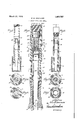
- Fig. 1 is a vertical sectional view of a core drill embodying a form of myv invention showing the parts in their relation during the down stroke of the outer barrel.
- Fig. 2 is a diagrammatic vertical sectional view of a core drill shown in Fig. 1, in which the. outer barrel is at the upper end ofits stroke; i
- Fig. 3 is a diagrammatic vertical sectional Viewv of the core drill shown in Fig. 1, the
- Fig. 4 is a sectional plan view on the lines 4-4, of Fig. 1.
- vter body 12 such cutterbody having a plu- Fig.'5 is a sectional 5 5 of Fig. 1.
- Fig. 6 is a sectional plan view on the lines 6-6 of fFig. 1.
- Fig.' 7 is a sectional plan view. on the lines i 7-7'ofFig. 1.
- the drill as illustrated, consists of an outer barrel 11, interiorly threaded at its lower end to receive the upperend of a cutplan view onl the lines rality of [cutters 13, the outer diameter of 05 which is slightly larger than the diameter of the outerbarrel.
- the outer barrel 11- is provided with .a series of perforations 14 and'15,for the purpose of permitting the egress of any accumulation of material between the two barrels.
- Th upper end of the outer barrel 11 is interiorly threaded to receive a coupling member 16, this cou ling member in the present instance constitutes an impact head or member for the'outer W5 barrel.
- FIG. 20 indicates the, inner barrel or core tube, terminating at itslower end in an annular cutter 21 provided with core catchers 22 which, in the present instance, consists of flat spring members secured at their lower ends by means of suitable rivets 23, the upper ends of the spring members extending inwardly as shown in Fig. 1.
- the inner barrel 20 is of increased diameter at its upper vend, forming a circular shoulder'Q/l, which shoulder Ais designed toy contact with the upper end or face 25 of the cutting member or body 12, during the, removal of the core drill from the well, there- ⁇ by preventing dislodgment of the inner barrel from the outer barrel.
- 26 indicates a head threaded onto the upper end of the inner barrel 20.
- 27 designates a passage in the head 26,' the upper end o f which isformed with.
- the cage .29 acts as an anvil to receive impact from the weight .hereinafter referred to. resting upon the upper end of the 'inner barrel 20, for the purpose of preventing large particles or cuttings from vpassin upward y through the passage 27 to the va ve seat.
- the operation of the device is as follows: Assuming that the core drill is in the position shown in Fig. 2, it is to be noted that the inner barrel is resting on the bottomy of the hole and the outer barrel is in elevated position. As the outer barrel descends, due to the weight of same and the supporting tools above, we may assume that it has descended to the position shown in Fig. 1 where the impact head 16 of the outer barrel is just about to strike the weight 36: rlhe continued downward movement of the outer ⁇ barrel causes the impact head 16 to strike the weight 36 with a. blow suiicient to compress the spring 35 and to permit the weight to strike the upper face ot the cage 29, 1mparting a blow thereto which causes the inner barrel to advance downwardly.
- the outer barrel As the outer barrel starts on its up stroke, it will have a tendency to carry the inner vbarrel upwardly on' the bottom of the hole, due to frictional contact of foreign matter between the barrels. rlhis tendency ot' the inner barrel to leave the bottom of the hole will be overcome by the weight 36, which insures the inner barrel remaining on the bottom of the hole.
- l. lin a reciprocating core drill the combination of an inner barrel; an outer barrel reciprocably mounted on the inner barrel; means for limiting the movement of the out-- er barrel on the inner barrel; resilient means on the inner barrel; a weight member supported on said resilient means and a head on said outer barrel arranged to engage said weight by impact.
- a reciprocating core drill the combination of: an inner barrel; an annular cutter on the lower end of said inner barrel; an outer barrel reciprocably mounted on said inner barrel; a lcutter' body on the lower end of said outer barrel; means for limiting .the reciprocative movement of' the outer barrel on the inner barrel; resilient means on said inner barrel; a weight supported on said resilient means, and weight engaging means on said outer barrel.
- a reciprocating core drill the comwearer hination of: an inner barrel; an annular cutter on the lower end of said inner barrel an outer barrel reciprocably mounted on said inner barrel; a cutter body on the lower end of said'outer barrel; means for limiting the reciprocative movement of the outer barrel on the inner barrel; a coiled compresv 'sion spring on the upper end of said inner barrel; a weight supported on said s ri-ng; weight engaging means on said outer arrel, and means on said inner barrel extending upwardly in said spring arranged to be engaged by said weight. 4
- a reciprocating core drill the combination of an inner barrel; an annular cutter on the lower end of said inner barrel; an outer barrel reciprocably mounted on said inner barrel; a cutter body on the lower end of said outer ⁇ barrel; a'shoulder on said inner barrel arranged to engage the top of said cutter body; resilient means on said inner barrel; a weight supported on said resilient means, and weight engaging means on said outer barrel.
- a reciprocating core drill the combination of an inner barrel; an annular cutteron the lower end of said inner barrel;
- an outer harrel reciprocably mounted on said inner barrel; a cutter body on the lower end of said' outer barrel; a head on said inner barrel; valve means on said head; a valve'cage on said inner barrel; a coiledv spring on said inner ⁇ barrel about said valve cage; a weight on said spring and a head on said outer barrel adapted to engage said weight.
Landscapes
- Engineering & Computer Science (AREA)
- Life Sciences & Earth Sciences (AREA)
- Geology (AREA)
- Mining & Mineral Resources (AREA)
- Physics & Mathematics (AREA)
- Environmental & Geological Engineering (AREA)
- Fluid Mechanics (AREA)
- General Life Sciences & Earth Sciences (AREA)
- Geochemistry & Mineralogy (AREA)
- Mechanical Engineering (AREA)
- Processing Of Stones Or Stones Resemblance Materials (AREA)
Description
March 27, 1928.
' R. B. GRAINGER STANDARD TooL coRE DRILL afl/)Wolfe led Oct 5 .1927
I-IIIIIIIII HTToe/vfy Patented Mar. 27, 1928.
carica.
REID B. GRAINGER, OF REDONDO BEACH, CALIFORNIA, .ASSIGNOR T ELLIOTT CORE DRILLIN G COMPANY, A CORPORATION OF CALIFORNIA.
STANDARD 'roofJ conn DRILL.
Application filed October 5, 192i'. Serial Nofz'lld.
My invention relates to core drills, such as are used in theart of drilling oils, being more particularly a core drill of the type known as the double barrel core drill, in
which the outer barrel reciprocates over the y inner' barrel, means being provided whereby the outer barrel is permitted to reciprocate freely over the outer barrel, throughout aA limited stroke.
W In core drills of lthe reciprocatory type, diiiculty has been encountered in holding the inner' barrel or core tube on the formation, at the time the outer barrel starts upwardly on its up stroke. If the inner barrel or core tubeis permitted to jump off the formation, I the core is damaged and either lost in whole or part, thereby bringing about a failure to recover a true specimen of the-formation and defeating the very purpose of the core drill.
It. is one of the principal objects of my invention to so construct a-core drill of the class described, in which provision is made to overcome any tendency of the inner barrel leaving the formation or bottom of the hole until the coring operation is completed.
ln carrying out the principal object of my invention, as above indicated, l provide a weight resiliently AJSupported on the inner barrel, such weight being free of the inside walls of the outer barrel and arrangedto receive impact from the outer barrel, to drive the inner barrel or core tube downward into the formation and heavy enough to insure contact of the inner. barrel with the bottom of the hole, during the up stroke of the outer barrel.
Other objects and advantages will appear hereinafter, from the following description.
Referring to the drawings which are for illustrative purposes only, I
Fig. 1 is a vertical sectional view of a core drill embodying a form of myv invention showing the parts in their relation during the down stroke of the outer barrel.
Fig. 2 is a diagrammatic vertical sectional view of a core drill shown in Fig. 1, in which the. outer barrel is at the upper end ofits stroke; i
Fig. 3 is a diagrammatic vertical sectional Viewv of the core drill shown in Fig. 1, the
outer barrel being shown at the end of its downward stroke.
Fig. 4 is a sectional plan view on the lines 4-4, of Fig. 1.
Fig. 6 is a sectional plan view on the lines 6-6 of fFig. 1.` Fig.' 7 is a sectional plan view. on the lines i 7-7'ofFig. 1.
The drill, as illustrated, consists of an outer barrel 11, interiorly threaded at its lower end to receive the upperend of a cutplan view onl the lines rality of [cutters 13, the outer diameter of 05 which is slightly larger than the diameter of the outerbarrel. The outer barrel 11-is provided with .a series of perforations 14 and'15,for the purpose of permitting the egress of any accumulation of material between the two barrels. Th upper end of the outer barrel 11 is interiorly threaded to receive a coupling member 16, this cou ling member in the present instance constitutes an impact head or member for the'outer W5 barrel.
20 indicates the, inner barrel or core tube, terminating at itslower end in an annular cutter 21 provided with core catchers 22 which, in the present instance, consists of flat spring members secured at their lower ends by means of suitable rivets 23, the upper ends of the spring members extending inwardly as shown in Fig. 1.
The inner barrel 20 is of increased diameter at its upper vend, forming a circular shoulder'Q/l, which shoulder Ais designed toy contact with the upper end or face 25 of the cutting member or body 12, during the, removal of the core drill from the well, there-` by preventing dislodgment of the inner barrel from the outer barrel. 26 indicates a head threaded onto the upper end of the inner barrel 20. 27 designates a passage in the head 26,' the upper end o f which isformed with. a seat for aball valve 28 in a cage 29l threaded to an extension 30, formed on the head 26. The cage .29 acts as an anvil to receive impact from the weight .hereinafter referred to. resting upon the upper end of the 'inner barrel 20, for the purpose of preventing large particles or cuttings from vpassin upward y through the passage 27 to the va ve seat.
34 indicates an anti-friction bearin` meinbcr mounted on the head 26, arrange to engage the inner face of the outer barrel 11. Seated on such anti-friction member 34 and 32 indicates a perforated plate 100 extending upwardly therefrom is a coil spring 35 which forms a resilient support for a heavy wieght 36.
The operation of the device is as follows: Assuming that the core drill is in the position shown in Fig. 2, it is to be noted that the inner barrel is resting on the bottomy of the hole and the outer barrel is in elevated position. As the outer barrel descends, due to the weight of same and the supporting tools above, we may assume that it has descended to the position shown in Fig. 1 where the impact head 16 of the outer barrel is just about to strike the weight 36: rlhe continued downward movement of the outer `barrel causes the impact head 16 to strike the weight 36 with a. blow suiicient to compress the spring 35 and to permit the weight to strike the upper face ot the cage 29, 1mparting a blow thereto which causes the inner barrel to advance downwardly.
As the outer barrel starts on its up stroke, it will have a tendency to carry the inner vbarrel upwardly on' the bottom of the hole, due to frictional contact of foreign matter between the barrels. rlhis tendency ot' the inner barrel to leave the bottom of the hole will be overcome by the weight 36, which insures the inner barrel remaining on the bottom of the hole.
What l claim is:
l. lin a reciprocating core drill, the combination of an inner barrel; an outer barrel reciprocably mounted on the inner barrel; means for limiting the movement of the out-- er barrel on the inner barrel; resilient means on the inner barrel; a weight member supported on said resilient means and a head on said outer barrel arranged to engage said weight by impact.
2. ln a reciprocating core drill, the combination of: an inner barrel; an annular cutter on the lower end of said inner barrel; an outer barrel reciprocably mounted on said inner barrel; a lcutter' body on the lower end of said outer barrel; means for limiting .the reciprocative movement of' the outer barrel on the inner barrel; resilient means on said inner barrel; a weight supported on said resilient means, and weight engaging means on said outer barrel.
3. ln a reciprocating core drill, the comwearer hination of: an inner barrel; an annular cutter on the lower end of said inner barrel an outer barrel reciprocably mounted on said inner barrel; a cutter body on the lower end of said'outer barrel; means for limiting the reciprocative movement of the outer barrel on the inner barrel; a coiled compresv 'sion spring on the upper end of said inner barrel; a weight supported on said s ri-ng; weight engaging means on said outer arrel, and means on said inner barrel extending upwardly in said spring arranged to be engaged by said weight. 4
5. lln a reciprocating core drill, the combination of an inner barrel; an annular cutter on the lower end of said inner barrel; an outer barrel reciprocably mounted on said inner barrel; a cutter body on the lower end of said outer` barrel; a'shoulder on said inner barrel arranged to engage the top of said cutter body; resilient means on said inner barrel; a weight supported on said resilient means, and weight engaging means on said outer barrel..
6. ln a reciprocating core drill, the combination of an inner barrel; an annular cutteron the lower end of said inner barrel;
'an outer harrel reciprocably mounted on said inner barrel; a cutter body on the lower end of said' outer barrel; a head on said inner barrel; valve means on said head; a valve'cage on said inner barrel; a coiledv spring on said inner` barrel about said valve cage; a weight on said spring and a head on said outer barrel adapted to engage said weight.
ln testimoni whereof,flt have hereunto setmy hand at' aos Angeles, California, this 28th day of Sept., 1927. l
REID B. GRAINGER.
@til
Priority Applications (1)
| Application Number | Priority Date | Filing Date | Title |
|---|---|---|---|
| US224234A US1663757A (en) | 1927-10-05 | 1927-10-05 | Standard tool core drill |
Applications Claiming Priority (1)
| Application Number | Priority Date | Filing Date | Title |
|---|---|---|---|
| US224234A US1663757A (en) | 1927-10-05 | 1927-10-05 | Standard tool core drill |
Publications (1)
| Publication Number | Publication Date |
|---|---|
| US1663757A true US1663757A (en) | 1928-03-27 |
Family
ID=22839804
Family Applications (1)
| Application Number | Title | Priority Date | Filing Date |
|---|---|---|---|
| US224234A Expired - Lifetime US1663757A (en) | 1927-10-05 | 1927-10-05 | Standard tool core drill |
Country Status (1)
| Country | Link |
|---|---|
| US (1) | US1663757A (en) |
Cited By (1)
| Publication number | Priority date | Publication date | Assignee | Title |
|---|---|---|---|---|
| US3169589A (en) * | 1958-08-21 | 1965-02-16 | Jr Albert G Bodine | Sonic method and apparatus for extruding flowable materials |
-
1927
- 1927-10-05 US US224234A patent/US1663757A/en not_active Expired - Lifetime
Cited By (1)
| Publication number | Priority date | Publication date | Assignee | Title |
|---|---|---|---|---|
| US3169589A (en) * | 1958-08-21 | 1965-02-16 | Jr Albert G Bodine | Sonic method and apparatus for extruding flowable materials |
Similar Documents
| Publication | Publication Date | Title |
|---|---|---|
| US3651867A (en) | Combination well clean-out tool and jar | |
| US1663757A (en) | Standard tool core drill | |
| US2266873A (en) | Overshot | |
| US3203482A (en) | Jarring devices | |
| US2214970A (en) | Combination well driving and boring tool | |
| US2184393A (en) | Paraffin removing device | |
| US2842343A (en) | Retractible bit | |
| US2712853A (en) | Paraffin remover | |
| US1819798A (en) | Collapsible bit | |
| US3409095A (en) | Percussion chatter hammer drill | |
| US2242602A (en) | Double duty fishing tool | |
| US1987853A (en) | Core catching means | |
| US1919510A (en) | Apparatus for lowering pipes in wells | |
| US2005989A (en) | Core barrel | |
| US1611504A (en) | Core barrel | |
| US2204844A (en) | Drilling and coring apparatus | |
| US1661426A (en) | Core drill | |
| US3409091A (en) | Percussion multi-blow gravity drill | |
| US2000389A (en) | Core catcher | |
| US1993258A (en) | Paraffin scraper for plunger lift devices | |
| US2345727A (en) | Fishing tool | |
| US1810391A (en) | Rotary action bit | |
| US2275960A (en) | Fishing apparatus | |
| USRE18045E (en) | Reuben c | |
| US1752154A (en) | Rod or tubing guide |