US1663751A - Coil-winding means - Google Patents
Coil-winding means Download PDFInfo
- Publication number
- US1663751A US1663751A US90003A US9000326A US1663751A US 1663751 A US1663751 A US 1663751A US 90003 A US90003 A US 90003A US 9000326 A US9000326 A US 9000326A US 1663751 A US1663751 A US 1663751A
- Authority
- US
- United States
- Prior art keywords
- washer
- stem
- spool
- coil
- coils
- Prior art date
- Legal status (The legal status is an assumption and is not a legal conclusion. Google has not performed a legal analysis and makes no representation as to the accuracy of the status listed.)
- Expired - Lifetime
Links
Images
Classifications
-
- B—PERFORMING OPERATIONS; TRANSPORTING
- B21—MECHANICAL METAL-WORKING WITHOUT ESSENTIALLY REMOVING MATERIAL; PUNCHING METAL
- B21C—MANUFACTURE OF METAL SHEETS, WIRE, RODS, TUBES, PROFILES OR LIKE SEMI-MANUFACTURED PRODUCTS OTHERWISE THAN BY ROLLING; AUXILIARY OPERATIONS USED IN CONNECTION WITH METAL-WORKING WITHOUT ESSENTIALLY REMOVING MATERIAL
- B21C47/00—Winding-up, coiling or winding-off metal wire, metal band or other flexible metal material characterised by features relevant to metal processing only
- B21C47/02—Winding-up or coiling
- B21C47/04—Winding-up or coiling on or in reels or drums, without using a moving guide
Definitions
- Another object of my'invention is asimple and eflicient means which is adjustable to adapt the same for a variety of-cross sectionally different coils.
- Anotherobject of my invention is asim- I ple and-eflicient coil windmg means which is adjustable to various forms of coils as well as to various thicknesses of coils and from "which the coils can be removed-with a minimum amount of time and' l'abor after they are wound.
- Another object of my invention is a simple and eflicient means of releasing and removing the wound coils from the winding means with a minimum amount of time and I labor.
- coilwinding apparatus embodying the feaapparatus with six spools each'of which is adjustable to permit a variety of differently formed coils to be formed or wound thereon.
- Fig. 4 is a longitudlnal section of the spool shown in Fig. 3 and shows a threaded I engagement between the'stem and the flange,
- my invention is a i spool to be ple and efficient means which-is adjustable Fig. 1 is a general perspective view of a tures of my invention and shows such an 23, 1926. Serial No. 90,003. g
- Fig. 5 is a transverse section of'the spool shown in Fig.3, taken on a plane indicated by'the line"5-'5 in Fig. 4 and shows the increasing depth ofthe grooves and the pins engaging the grooves in the final and definite position on the -stem.: 1 Similar reference characters refer to similar parts throughout the views. 5
- the frame'A is supported in the housing B, either'fixedly or rotatably, and has the C, described later in this specification, are
- each of these spools has amember extending through one of the slots and can be adjusted by sliding the spool' to desired. position within 'the limits of the slot. .7
- This structure is intend- I ed to illustrate, generally, howiny inven-' tion may be applied to a device adapted to form-coils of various forms.
- the frame D is supported in the housing E, either fixedlyor rotatably, and has'the 'sl0ts'16 and 1.7.1
- Two spools C are mounted on the frameD and each of thesespools has a member extending through one of the slots and can be adjusted by sliding the. spool to 'desired position within the limits of the slot.
- the stem F has the externally threaded end 18, the conical end-19, and, in the pres ent'instance, two grooves 20 and 21..
- each of the grooves is r disposed cireumferentially and that the depththereof increases progressively (Fig. 5) and that each groove has a lead, or in other words, is at an angle to the longitudinal as well as to the traverse axis of the spool (Fig. 1). The object of this increasing depth and this lead of the grooves will appear presently.
- the flange Ur has the hub 22 and the counterbore 23 and the internally threaded opening 24 adapted to the externally threaded portion 18 of the stem F. This threaded engagement between the stem and the flange permits the flange to be adjusted longitudinally on the stem and thereby adaptsthe spool to be adjusted for different thicknesses of coils; further details of which will appear later in this specification.
- the counterbore 23 is provided to reduce the length of the threaded portion 18 so that. a wider range of adjustment of the flange is possible without bringing the threaded portion 18 into the winding space between the flange and the washer.
- the springs 30 are disposed in the washer H between the outer ends of the pins 28 and the inner ends of the screws 31 which are threaded into the'washer H.
- the object of the springs 30 is to normally retain the pins 28 inwardly and to provide resiliency for these pins so that they may be pushed back into the body of the washer when necessary.
- the grooves 20 and 21 are cut into the material of the stern F and are therefore fixed.
- the pins 28 are also fixed in position (exceptlongitudinally) in the washer H.
- the washer H attains a fixed position on the stem F when the ends 29 of the pins engage the deepest portions of thegrooves 20 and 21 as seen in Fig. 4.
- the flange G is threaded to the end 18 of the stem F and, therefore, can be screwed back and forth on the stem and thereby can. be adjusted to any desired and available distance from the fixed washer H to attain any available desired thickness of coils when the wire of the coil is wound between the flange G and the washer H.
- That vportionof'the end 18 of the stem F which projects outside of the flange G may extend through the slots in either Fig. '1, or
- any other support means and the spool as a unit may be securely held in position by the nut 32 which is threaded to the end 18 of thestem F.
- the nuts 32 permit of the spools being securely anchored in ad usted position so that any number ofcoilsof the same form may be Wound.
- each of the spools also presents a decided advantage in that the coils can be removed from'the spools without any tools and with'the least amount of time and labor.
- the coil can easily be removed from the spools by merely imparting a rotative movement to the WasherH and then pulling the same longitudinally off of the stem whereupon the wound coil can readily be taken off of the spools.
- cluding a stem having a groove, a washeradapted to be attached to and removed from said stem, and a pin resiliently mounted in said washer and one end thereof adapted to engage said groove to locate said washer on.
- cluding a stem having a groove and a'conical end, a washer adapted to beattached to and removedfrom said stem, a pin-resiliently mounted in said washer and one end thereof adapted to. engage said grooveto locate said washeronsaid stem and to retain the same thereon, and a shoulder in said washer and adapted to abut the conical end of said stem to primarily locate said washer on said stem in approximate position.
- a spool of the character described including, a stem having one end thereof threaded and the other end thereof conical and a groove intermediate the ends thereof, a flange threaded to the threaded end of said stem, a washer adapted to be attached to and removed from said stem, a in resiliently mounted in said washer an one end thereof adapted to engage said groove to locate said washer on said stem and to re-- tain the same thereon, and a shoulder in said washer and adapted to abut the conical end of said stem to primarily locate said washer on said stem in approximate position.
- a spool to wind the ,WIIGS of a co l thereon, a washer 1 washer in; a definite position on said spool, and saidmeans mounted to recede into'saidwasher and out of engagement with the spool when said washeris partly rotated.
- a spool of the character described including, a stem, and a washer attachable to and locatable on said stem and having a bore and a shoulder therein; said stein having a conical end abutting said sh'oulder when said washer is lo'cated in a position approximate to the final locating position thereof.
- a spool of the character described including, a stem, a washer attachable to said stem, and resiliently mounted means between said stem and said washer to effect to engage the other one of said walls to move 7 the locating of said washeron said stem; said stem having a conical end to push said resiliently mounted means out of the locating position thereof during the beginning of the movement which attaches said washer to said stem.
- a spool of the character described including, a stem, a washer attachable to said stem, a pin movable insaid washer, and a spring between said pin and said washer and normally extending said pin into the bore of said washer; said pin having a conical end to push said pin out of said bore during the beginning of the movement which attaches said washer to said stem.
- a coil winding apparatus including a frame having a plurality of angularly disposed slots, a plurality of spools eachhaving a stem insertable into and adjustable in either one of said slots, the end of each of said stems being conical and each of said stems being provided with a groove having a lead, a plurality of washers each having a bore adapted to said stems and'attachable to and removable from the same, and a pin movable in each of said washers and normally extending into said bore thereof; said con: ical end ofthe stem contacting said pin to move the same out of said bore while said washer is; being attached to said stem and said lead of the groove arranged so that'said in en 'a es the sides thereof to locate saidwasher longitudinally on said stemupon arotative movement thereof in one direction and to move said washer away from a coil wound on said spool upon a rotative movement thereof in the opposite direction.
- a coil winding apparatus including a spool having astem provided witha groove extending circumferentially and having Walls inclined circumferentially, awasher attachable to and removable from said spool,
- a coil winding apparatus including a spool member, a coil confining memberat tachable to said spool member, a movable element between said members and adapted to normally obstruct the attachment of said con-- fining member to said spool member, and taper surface on one of said members toengage said movable element to move the same into I rality of spools each having a stem, said 7 stems extendable through said slots and mov able therein to adjust said spools to wind variously formed coils thereon, and fastening means to clamp said spools onto said frame in the adjusted position thereof.
- a coil winding apparatus including a spool member, a coil confiningmember attachable to and removable from said spool member, tapering surface on one of said 7 and a movable tween said members and adapted to engage said tapering surface to locate said confining member in a definiteposition on. said spool member when the same is attached thereon and to move said confining member longitudinally away from said spool member during the first portion of the removal movef dented tapering surface in said one member to engage said movable element to retain sald confining member on said spool member longitudinally in both directions.
Landscapes
- Engineering & Computer Science (AREA)
- Mechanical Engineering (AREA)
- Storage Of Web-Like Or Filamentary Materials (AREA)
Description
March 27, 1928. I 1,663,751
A. J. FATHAUER COIL WINDING MEANS Filed Feb. 23. 1926 alien care-1 AL INIT. rnrrinunn, on cnE'via Au'noI- iio.
I coin-WINDING enus.
- Application filed February 7 My invention relates to apparatus or devices or means for winding coils generally and for winding such coils as armature coils specifically. I I 6 One of the objects of simple and efficientcoil winding' means and adapted to reduce the coil winding operations to a minimum. I V I -Another object of my invention is a simto adapt the same for a variety of diilerently formed coils. V 1
Another object of my'invention is asimple and eflicient means which is adjustable to adapt the same for a variety of-cross sectionally different coils. i
, Anotherobject of my invention is asim- I ple and-eflicient coil windmg means which is adjustable to various forms of coils as well as to various thicknesses of coils and from "which the coils can be removed-with a minimum amount of time and' l'abor after they are wound. I
Another object of my invention is a simple and eflicient means of releasing and removing the wound coils from the winding means with a minimum amount of time and I labor. 1
In the accompanying drawing I have il- 30 lustrated my invention as embodied in cer-' tain mechanisms but I am aware that such embodiment is not the only embodiment which is possible with my invention and that modifications may be made as to structural details as well as to'generalarrangement, within the scope of thevappended claims. W I
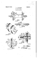
In the accompanying drawing coilwinding apparatus embodying the feaapparatus with six spools each'of which is adjustable to permit a variety of differently formed coils to be formed or wound thereon. I
unitary spool on a larger scale, embodying the features of my invention. I I
Fig. 4: is a longitudlnal section of the spool shown in Fig. 3 and shows a threaded I engagement between the'stem and the flange,
my invention is a i spool to be ple and efficient means which-is adjustable Fig. 1 is a general perspective view of a tures of my invention and shows such an 23, 1926. Serial No. 90,003. g
and two' resilient pins in the washer and engaging two. circumferentially disposed grooves in the stem, and the lead of the grooves, and a conical end on the stemabutting a shoulder in the washer, and a threaded end of the stem projecting beyond the flange and having a nut to permit/ the attached to a winding apparatus. g
Fig. 5 is a transverse section of'the spool shown in Fig.3, taken on a plane indicated by'the line"5-'5 in Fig. 4 and shows the increasing depth ofthe grooves and the pins engaging the grooves in the final and definite position on the -stem.: 1 Similar reference characters refer to similar parts throughout the views. 5
Referring now specifically to Fig. 1:--. The frame'A is supported in the housing B, either'fixedly or rotatably, and has the C, described later in this specification, are
i mounted on this frame and each of these spools has amember extending through one of the slots and can be adjusted by sliding the spool' to desired. position within 'the limits of the slot. .7 This structure is intend- I ed to illustrate, generally, howiny inven-' tion may be applied to a device adapted to form-coils of various forms.
Referring now specifically to Fig. 2:'
The frame D is supported in the housing E, either fixedlyor rotatably, and has'the 'sl0ts'16 and 1.7.1 Two spools C, described later in this specification, are mounted on the frameD and each of thesespools has a member extending through one of the slots and can be adjusted by sliding the. spool to 'desired position within the limits of the slot.
Referring nowspecifically tlie spools Gshown in. Figs. 3, 4, and 5 on a larger scale:
The stem F has the externally threaded end 18, the conical end-19, and, in the pres ent'instance, two grooves 20 and 21.. I
This structure is intended to illustrate, generally, how my inventioninay be applied It is observed that'each of the grooves is r disposed cireumferentially and that the depththereof increases progressively (Fig. 5) and that each groove has a lead, or in other words, is at an angle to the longitudinal as well as to the traverse axis of the spool (Fig. 1). The object of this increasing depth and this lead of the grooves will appear presently.
The flange Ur has the hub 22 and the counterbore 23 and the internally threaded opening 24 adapted to the externally threaded portion 18 of the stem F. This threaded engagement between the stem and the flange permits the flange to be adjusted longitudinally on the stem and thereby adaptsthe spool to be adjusted for different thicknesses of coils; further details of which will appear later in this specification.
The counterbore 23 is provided to reduce the length of the threaded portion 18 so that. a wider range of adjustment of the flange is possible without bringing the threaded portion 18 into the winding space between the flange and the washer.
, presently.
The springs 30 are disposed in the washer H between the outer ends of the pins 28 and the inner ends of the screws 31 which are threaded into the'washer H. The object of the springs 30 is to normally retain the pins 28 inwardly and to provide resiliency for these pins so that they may be pushed back into the body of the washer when necessary.
The grooves 20 and 21 are cut into the material of the stern F and are therefore fixed. The pins 28 are also fixed in position (exceptlongitudinally) in the washer H.
Therefore, the washer H attains a fixed position on the stem F when the ends 29 of the pins engage the deepest portions of thegrooves 20 and 21 as seen in Fig. 4. I
The flange G is threaded to the end 18 of the stem F and, therefore, can be screwed back and forth on the stem and thereby can. be adjusted to any desired and available distance from the fixed washer H to attain any available desired thickness of coils when the wire of the coil is wound between the flange G and the washer H.
That vportionof'the end 18 of the stem F which projects outside of the flange G may extend through the slots in either Fig. '1, or
F ig. 2, or'through any other support means and the spool as a unit may be securely held in position by the nut 32 which is threaded to the end 18 of thestem F.
thereby permits of a variety of differently formed coils to be wound; the nuts 32 permit of the spools being securely anchored in ad usted position so that any number ofcoilsof the same form may be Wound.
In addition to the adjustable advantages of the spools mentioned, each of the spools also presents a decided advantage in that the coils can be removed from'the spools without any tools and with'the least amount of time and labor.
After the spools have been adjusted to .desired position on the frame to attain a desired form of coil, andythe flange G has been adjusted to attain a desired thickness of coil, and the coil has been wound on the spools, the coil can easily be removed from the spools by merely imparting a rotative movement to the WasherH and then pulling the same longitudinally off of the stem whereupon the wound coil can readily be taken off of the spools.
The operation of thewasher H, to remove the same from the stem, is as follows:
Upon the mentioned rotative movement of the washer, the ends 29 of the pins 28 follow the grooves 20 and 21. Since the grooves are of increasing depth, the pins 28 are pushed into the body of the Washer against the springs 30, as the washer is rotated, until the ends 29 leave the grooves and rest against the outer surface of the stem F whereupon a longitudinal pull, outwardly, of the washer slides the same off of the stem.
It is observed here that the grooves 20 and 21 have a lead as previously described; now when the ends 29 engage the grooves and when the coil has been Wound, and the washer is given a rotative movement, the
ends 29 follow the groovesand, since the V grooves lead away from the coil, the washer is moved away from the coil and thereby prevents the washer from abrading or otherwise injuring the insulation of the coil wire or in any other manner affecting the coil. 7
v The operation of the washer, to insert the same on the stem F, is as follows z- Normally, the springs 30 retain the pins 28 in their innermost positions; the end 19 of the stem F is conical and may have the slot shown to facilitate the adjustment of the spool on a frame. I
When the bore of the washer H is teleseop'ed over the .conical end 19 of the stem F, the pins 28are'pushed inwardly and this telescoping or pushing inwardly of the washer is continued until the conical end 19 ends 29 follow the gro0ves20 and 21 until the ends 29 abut the deepest and final location portion at one end of the grooves and arrest further rotative movement of the washer. Even if the washer is not manually rotated to this final locating position,-the springs 30 normally exert a pressure on the pins longitudinally and, since the ends of the pins abut the inclined bottoms of the grooves, the action of the springs onthe pins will automatically rotate the washers to final location position in casethe operator fails to rotate the washer to the final location position. 7
It is believed that the foregoing description is, sufiiciently clear to show what myinvention is and how it may be applied and that the present invention provides a means .for winding coils with an expenditure of a and removed from said stem, and a pin resilient in said washer and adapted to engage thesides and the bottom of said groove to locate and to retain said washer on said stem.
3. A spool of the character described, in-
cluding, a stem having a groove, a washeradapted to be attached to and removed from said stem, and a pin resiliently mounted in said washer and one end thereof adapted to engage said groove to locate said washer on.
cluding, a stem having a groove and a'conical end, a washer adapted to beattached to and removedfrom said stem, a pin-resiliently mounted in said washer and one end thereof adapted to. engage said grooveto locate said washeronsaid stem and to retain the same thereon, and a shoulder in said washer and adapted to abut the conical end of said stem to primarily locate said washer on said stem in approximate position.
5. A spool of the character described, including, a stem having one end thereof threaded and the other end thereof conical and a groove intermediate the ends thereof, a flange threaded to the threaded end of said stem, a washer adapted to be attached to and removed from said stem, a in resiliently mounted in said washer an one end thereof adapted to engage said groove to locate said washer on said stem and to re-- tain the same thereon, and a shoulder in said washer and adapted to abut the conical end of said stem to primarily locate said washer on said stem in approximate position.' I
in said washer to abut the conical end of said stem to primarily locate said washer on said stem ,in' approximate position, a pin resiliently mounted insa d washer, and said pin adapted to engage said groove to defi nitely locate said washer on said stem each time said washer'is attached to said stem.
7. In a coil winding apparatus, a spool to wind the ,WIIGS of a co l thereon, a washer 1 washer in; a definite position on said spool, and saidmeans mounted to recede into'saidwasher and out of engagement with the spool when said washeris partly rotated.
,8. A spool of the character described including, a stem, and a washer attachable to and locatable on said stem and having a bore and a shoulder therein; said stein having a conical end abutting said sh'oulder when said washer is lo'cated in a position approximate to the final locating position thereof.
aA.-s Qo1 of the character described A said washer-is located in a position approximate to the final locating position thereof,
10. A spool of the] character-described,
including, astem having a groove, .awasher attachable to and locatable on said stem and having a bore andashoulder therein, and a V pinvresiliently mounted insaid washer and v normally projecting into said bore and engaging said groove when said washer is in locating position on said stem; said stem having a conical end moving said pin out of said bore while said washer is being attached tosaid stem and abutting said shoulder when said washer is attached to said stem in a position approximate to the final locating f position thereof. a
11. A spool of the character described including, a stem, a washer attachable to said stem, and resiliently mounted means between said stem and said washer to effect to engage the other one of said walls to move 7 the locating of said washeron said stem; said stem having a conical end to push said resiliently mounted means out of the locating position thereof during the beginning of the movement which attaches said washer to said stem. 7
a 12. A spool of the character described including, a stem, a washer attachable to said stem, a pin movable insaid washer, and a spring between said pin and said washer and normally extending said pin into the bore of said washer; said pin having a conical end to push said pin out of said bore during the beginning of the movement which attaches said washer to said stem.
13. A coil winding apparatus including a frame having a plurality of angularly disposed slots, a plurality of spools eachhaving a stem insertable into and adjustable in either one of said slots, the end of each of said stems being conical and each of said stems being provided with a groove having a lead, a plurality of washers each having a bore adapted to said stems and'attachable to and removable from the same, and a pin movable in each of said washers and normally extending into said bore thereof; said con: ical end ofthe stem contacting said pin to move the same out of said bore while said washer is; being attached to said stem and said lead of the groove arranged so that'said in en 'a es the sides thereof to locate saidwasher longitudinally on said stemupon arotative movement thereof in one direction and to move said washer away from a coil wound on said spool upon a rotative movement thereof in the opposite direction.
14. A coil winding apparatus including a spool having astem provided witha groove extending circumferentially and having Walls inclined circumferentially, awasher attachable to and removable from said spool,
and a member mounted in said washer and adapted to move into said groove to engage one of said walls to locate said washer on said spool in a definite position upon a rotative movement thereof in one direction and said washer longitudinally and away from said spool upon a rotative movement thereof in the opposite direction.
- members 15. A coil winding apparatus including a spool member, a coil confining memberat tachable to said spool member, a movable element between said members and adapted to normally obstruct the attachment of said con-- fining member to said spool member, and taper surface on one of said members toengage said movable element to move the same into I rality of spools each having a stem, said 7 stems extendable through said slots and mov able therein to adjust said spools to wind variously formed coils thereon, and fastening means to clamp said spools onto said frame in the adjusted position thereof.
17. A coil winding apparatus including a spool member, a coil confiningmember attachable to and removable from said spool member, tapering surface on one of said 7 and a movable tween said members and adapted to engage said tapering surface to locate said confining member in a definiteposition on. said spool member when the same is attached thereon and to move said confining member longitudinally away from said spool member during the first portion of the removal movef dented tapering surface in said one member to engage said movable element to retain sald confining member on said spool member longitudinally in both directions.-
' ALVIN J. FAT AUERQ element be
Priority Applications (1)
| Application Number | Priority Date | Filing Date | Title |
|---|---|---|---|
| US90003A US1663751A (en) | 1926-02-23 | 1926-02-23 | Coil-winding means |
Applications Claiming Priority (1)
| Application Number | Priority Date | Filing Date | Title |
|---|---|---|---|
| US90003A US1663751A (en) | 1926-02-23 | 1926-02-23 | Coil-winding means |
Publications (1)
| Publication Number | Publication Date |
|---|---|
| US1663751A true US1663751A (en) | 1928-03-27 |
Family
ID=22220630
Family Applications (1)
| Application Number | Title | Priority Date | Filing Date |
|---|---|---|---|
| US90003A Expired - Lifetime US1663751A (en) | 1926-02-23 | 1926-02-23 | Coil-winding means |
Country Status (1)
| Country | Link |
|---|---|
| US (1) | US1663751A (en) |
Cited By (1)
| Publication number | Priority date | Publication date | Assignee | Title |
|---|---|---|---|---|
| US2554897A (en) * | 1947-12-09 | 1951-05-29 | Landis Sons Inc Ab | Swift |
-
1926
- 1926-02-23 US US90003A patent/US1663751A/en not_active Expired - Lifetime
Cited By (1)
| Publication number | Priority date | Publication date | Assignee | Title |
|---|---|---|---|---|
| US2554897A (en) * | 1947-12-09 | 1951-05-29 | Landis Sons Inc Ab | Swift |
Similar Documents
| Publication | Publication Date | Title |
|---|---|---|
| US2599077A (en) | Rotary tool for scraping tube interiors | |
| US1663751A (en) | Coil-winding means | |
| US2399138A (en) | Screw holding attachment for screw drivers | |
| US2703684A (en) | Film reel | |
| US2542580A (en) | Reinforcing tying wire reel | |
| US4433501A (en) | Fishing lure retrieving device | |
| US2497550A (en) | Fastening device | |
| US3053472A (en) | Reel for metal snakes | |
| US2880992A (en) | Cable support and retractor | |
| US2336818A (en) | Cable tensioner | |
| US2006355A (en) | Method and apparatus for forming wire loops | |
| US2538787A (en) | Valve control means | |
| US1663305A (en) | Paper holder | |
| GB1161265A (en) | Anchor Assembly for a Camera | |
| US2212784A (en) | Well casing perforation cleaner | |
| US1625593A (en) | Tire cover | |
| US3053003A (en) | Audible signal device for fishing poles | |
| US2710111A (en) | Can opener | |
| US1349565A (en) | Plumb-bob | |
| US2149395A (en) | Tire contracting tool | |
| DE600567C (en) | Roll film processor | |
| US2280970A (en) | Contracting mandrel | |
| US1939546A (en) | Means for controlling concavoconvex rules | |
| US1611308A (en) | Bait connecter | |
| US3124100A (en) | Flag pole |