US1663706A - Hosiery-drying form - Google Patents
Hosiery-drying form Download PDFInfo
- Publication number
- US1663706A US1663706A US146682A US14668226A US1663706A US 1663706 A US1663706 A US 1663706A US 146682 A US146682 A US 146682A US 14668226 A US14668226 A US 14668226A US 1663706 A US1663706 A US 1663706A
- Authority
- US
- United States
- Prior art keywords
- channel
- wings
- steam
- channels
- hollow
- Prior art date
- Legal status (The legal status is an assumption and is not a legal conclusion. Google has not performed a legal analysis and makes no representation as to the accuracy of the status listed.)
- Expired - Lifetime
Links
- 238000001035 drying Methods 0.000 title description 15
- 238000010438 heat treatment Methods 0.000 description 12
- 239000012530 fluid Substances 0.000 description 9
- 238000005192 partition Methods 0.000 description 4
- 238000010276 construction Methods 0.000 description 3
- 239000002184 metal Substances 0.000 description 3
- 210000003414 extremity Anatomy 0.000 description 2
- 230000001141 propulsive effect Effects 0.000 description 2
- 239000002274 desiccant Substances 0.000 description 1
- 238000006073 displacement reaction Methods 0.000 description 1
- 101150012763 endA gene Proteins 0.000 description 1
- 210000003141 lower extremity Anatomy 0.000 description 1
- 230000004048 modification Effects 0.000 description 1
- 238000012986 modification Methods 0.000 description 1
- 239000000615 nonconductor Substances 0.000 description 1
Images
Classifications
-
- D—TEXTILES; PAPER
- D06—TREATMENT OF TEXTILES OR THE LIKE; LAUNDERING; FLEXIBLE MATERIALS NOT OTHERWISE PROVIDED FOR
- D06C—FINISHING, DRESSING, TENTERING OR STRETCHING TEXTILE FABRICS
- D06C5/00—Shaping or stretching of tubular fabrics upon cores or internal frames
- D06C5/005—Shaping or stretching of tubular fabrics upon cores or internal frames of articles, e.g. stockings
Definitions
- Application md November invention relates to vhollow metall forms, particularly Vthose intended for the drying, of hosiery by means of steam, al-
- Forms of thisfcharacter have been Vmade completely hollow; orv they have been provided with a longitudinally extending par-v tition terminating a greater ⁇ or less distance,
- the object of my invention is to provide a new form that is particularly adapted for internal steam heating and that will oper- Aate efficiently under all conditions and ⁇ for "all purposes.v
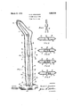
- the peculiar advantages of my. ⁇ improved drying form, as well as its construction and mode'or1 operation, are. JfullyV explained in connection with the description of the embodiments of my invention yshown iny t-he annexed. drawings, inv which Fig. 1 is a longitudinal 4sectional view of a hollow metal'drying form embodying my invention in a preferred form.
- Figs. 2, Y 3, et and 5 are Ycross-sections through Fig. l on the lines 2-2,'13-3, H and 5 5 respectively.
- Fig. 6 is adiagram of a modified arrangement of steam-conveying channels. i l
- the shell c ofthe hosiery drying form is shown as conveniently mounted on a pippe a, which functions as both an air-escapey pipe and a pipe for earryingoff exhaustA or condensed steam, and with which the interior of the shell communicates by meansv of holes b, o in pipe a.
- Extending within ⁇ pipe b is a steam-supply pipe-*0,whichis provided with a nozzle alV that yalso communicates with the interior of shell e.
- the total length of the channel Amust be, however, substantially less than the distance to whichl it is desired to effectively lconvey the steam atthe start of thedrying operation; and inasmuch as it is desired to convey the steam toalmost the extreme toe-end ofthe form, the-upper or outlet end of the channel 7c should terminate at a ⁇ substantial distance from thetoe endk of the form.
- the upper or outlet-end of channel jy terminates relatively.k near the lower end of v the form'.
- the wings 7' converge from the inlet of the channely toward its outlet, as shown in- F ig. l; although itis permissible, but less desirable, to' forni the -lower end of the channel by means ,of parallel wings relatively widelyv spaced apart, and
- the lower extremities 0I" wings g extend vsubstantially below the upperk extremities of wings j", so as to provide two .vertically extending passages connecting chan-rV 16,76 of substantial length nel g with the chambers m, m.
- the channel g may extend all the way to the toe of the form; but,.in the typefof form adapted for general use, one or'more' other similarly formed channels will be provided.
- Fig. l I have sli-own al third channel it, arranged above channel rg, and
- channel g has with respect to channel f; and a fourth channel c', ar-
- channel h has with respect to channel g, or channel g with respect to channel f.
- the uppermost channel whatever the number of the channels may be, terminates, preferably, a very short distance from the toe end ot' the form.
- the form is cold it is,'of course, filled with air, and, as hereinbefore stated, if the forni be absolutely-hollow, it is practically impossible to displace the air by introducing steam, whether or not a separate hole be providedV for the escapecf air and condensed steam.
- the form becomes airbo'und 5 that is, a pocket of air remains in the' toe end of the form which acts as a nonconductor of heat and prevents a proper heating of the foot end of the'form, which end can only mecanicperfectly heated byvv conduction of heat through the metal of the form.
- thesteam flowing through a relatively narrow series of channels,'iows rapidly to the toe end of the form and drives the airl within the channels ahead ot it and into the toe end of the form and also downward through passages c and establishes a downward circulation of air through chambers m, m, within which by far the larger volume of the form is contained.
- the air is driven out of the form speedily and thoroughly.
- the invention. isv also of particular advantage as applied to that type of form that' is provided with a removable toe' piece, such as n, Fig. l.
- a removable toe' piece such as n, Fig. l.
- a hollow drying form comprising a shell adapted to the shape of the article intended to be dried, and channels arranged in a series extending from theibase of the form toward and terminating short of its closed end and through which heating fluid is ada ted to successively pass, the approximating ends of two adjacent channels overlapping'and being spaced apart to allow the heating Huid to escape into the interior of the form outside the channels and at points elatively distant from opposite ends of the orm.
- a hollow ydrying form comprising a shell adapted to the shapel of the article intended to be dried, and channels arranged in a series extending from the base of the form toward and terminating short of its closed end and through which heating fluid is adapted to successively pass, the-approximating ends of twoadjacent channels being of substantially different widths and the narrower end of one channel extending into the wider end ofthe adjacentichannel so as to aiord a passage which extends longitudinally of the form.l
- a hollow drying form comprising a shell adapted to the shape of the article intended to be dried, and channels arranged in a series extending from the base of the form toward and terminating short of its closed end and through which heating liuid isiadapted to successively pass, the approximatingends of two yadjacent channels being of substantially different vwidths and the,v
- a 'hollow Adrying ⁇ form comprising a shell adapted tothe shape ofthe article intended to be dried, and channels arranged in-a series extending i'rom the base ofthe, form toward and terminating short of its closed end and through which heating fluid l is adapted to successively passfthe outlet end Yof a channel nearer the base of thel n form being substantially narrower than, and V above the level of, the approximating end of an adjacent channel nearer the closed endA oi' the form so as to provide means for the escape of fluid into the' interioro the form;v
- a hollow drying form comprising 4'a shell adapted to the shape of the article intended to be dried and channels arranged 1n a series extending from the base of the orin toward and terminating short of its closed end and through which heating fluid is adapted to successively pass, theoutlet end of a channel nearer the base of the form being substantially narrower than. theap- '.proximating end of ank adjacent channel" nearer the closed end ofthe form and projecting into the inlet end of thesecond channel a substantial distance soas to aord a iuid-escape passage Vot substantial length extending lengthwise of the form in a direction opposite to that of the infiowing heating Y fluid.
- a hollow drying form comprising a the base of the form extending into the inlet end of the next adjacent channel nearer the closed end of the form and spaced from the wings of the second channel so as to afford a pair of passages extending lengthwise of c the form toward its base.
- VA hollow drying form comprising a shell adapted to the shape of the article being dried,fand pairs of wings extending vbetween opposing walls of the shell and arranged to form channels a series of which Y extends from thel base of the form toward and' terminates short of its closed end and successively7 through which channels the wings forming the inlet end of theadjacent channel, the adjacent extremities of the two pairs of wings being positioned to provide a pair of passages each formed between opposite wings of the-two channels and opposite walls of the shell.
- a hollow drying form comprising a shellvadapted to the shape of the article'intended tobedried, andtwo series of wings extendingr between opposite walls of the 'form on opposite sides of its longitudinal center l1ne,-the wings ot' eachV series being spaced apart to formtluidpassages adapted to promote. the uniform circulation of the heating Huid throughout the interior of the form.
- a hollow drying form comprising a shell adapted to the shape of the article intended to befdried, and two series of wings.
- a hollow. drying form comprising'a shell adapted to theA shape of the articleintended' to be dried, and two series of wings extending between opposite walls ⁇ v of the: form on opposite sides of its longitudinal, center line, the wings of each series beingso,
- a hollow drying form comprising a shell adapted to the shapeof thearticlezto" be dried, andtwo series of wingsextendingI longitudinally of the form betweenofppositef walls thereof, the wings of eaohseriesV being spaced apart to form fluid passages adaptedy to promote the uniform circulationv onty the heating fluid throughout the interior of the# form.
- a hollow drying form comprisinga.
- a hollow dryingy formv comprising ak shell adapted to the shapeof thevarticlefto: be dried, and two series of wings extendinglongitudinally of the form between opposite walls thereof, the wings of each series being, so disposed that the lower end of; one wing extends along, and outside of, and is spaced from, the upper end otv the wing belovwit.
Landscapes
- Engineering & Computer Science (AREA)
- Textile Engineering (AREA)
- Treatment Of Fiber Materials (AREA)
Description
March 27, 192s. 1,663,706
H. E. HOUSEMAN f HOSIERY DRYING FORM Filed Nov. 6. 1926 `Haro/Q E. /Vaaswzarz v though not necessarilylimited to such forms.
Patented Mar. 27, i928.,
HAROLD E. HOUSEMANLOF EDGE MOOR, IDELAVVARE.-
v HOSIERY-DRYING FORM.
Application md November invention relates to vhollow metall forms, particularly Vthose intended for the drying, of hosiery by means of steam, al-
Forms of thisfcharacter have been Vmade completely hollow; orv they have been provided with a longitudinally extending par-v tition terminating a greater` or less distance,
from the toe end of the orm'and permit-l ting a luid circulation up through one halt of the form ,and down ,through the other,
half; or a steam inlet pipe has been provided tliat extends throughV the `torni 4and terminates a greater or less distance from the -toe end ofthe forni. The different fknown types of hollow steam heated forms are all, with the exception of the completely hollow form, operative under all conditions, but some of them fail to operate with maximumV eiiciency under any condition, while none of them operates with real efiicieiicy under all conditions.
The object of my invention is to provide a new form that is particularly adapted for internal steam heating and that will oper- Aate efficiently under all conditions and `for "all purposes.v The peculiar advantages of my.` improved drying form, as well as its construction and mode'or1 operation, are. JfullyV explained in connection with the description of the embodiments of my invention yshown iny t-he annexed. drawings, inv which Fig. 1 is a longitudinal 4sectional view of a hollow metal'drying form embodying my invention in a preferred form.
Figs. 2, Y 3, et and 5 are Ycross-sections through Fig. l on the lines 2-2,'13-3, H and 5 5 respectively. f
Fig. 6 is adiagram of a modified arrangement of steam-conveying channels. i l
The shell c ofthe hosiery drying form is shown as conveniently mounted on a pippe a, which functions as both an air-escapey pipe and a pipe for earryingoff exhaustA or condensed steam, and with which the interior of the shell communicates by meansv of holes b, o in pipe a. Extending within` pipe b is a steam-supply pipe-*0,whichis provided with a nozzle alV that yalso communicates with the interior of shell e.
Extending between opposite walls of the shell are two wings f, fforming between them a steam-conveying channel which communicates with nozzle al and which extends longitudinally partly through about the e, 192e. serial No. 146,632.'
center of the forni (that is, short midway bet-Ween the reduced opposite ends of the forni) for a distance which maybe varied within wide limits. The total length of the channel Amust be, however, substantially less than the distance to whichl it is desired to effectively lconvey the steam atthe start of thedrying operation; and inasmuch as it is desired to convey the steam toalmost the extreme toe-end ofthe form, the-upper or outlet end of the channel 7c should terminate at a` substantial distance from thetoe endk of the form. Preferably, the upper or outlet-end of channel jy terminates relatively.k near the lower end of v the form'.
Preferably, also, the wings 7' converge from the inlet of the channely toward its outlet, as shown in- F ig. l; although itis permissible, but less desirable, to' forni the -lower end of the channel by means ,of parallel wings relatively widelyv spaced apart, and
to form the upper end of the channel byv means of parallel wingsy separated'by a slibstantially narrower space, as shown at 0 in tions are permissible, as will be understood fromy the explanationotl Vthe mode of operation hereinafter made. i
VIn the type of form adaptedfor mostA uses, theupper end of `the lower steam-conveying channel will terminate relatively near the bottom of the' form, asshown in' Fig. l.v Whatever theA lengthof channel f lsa y8H F ig. 6; and still other obvious modifica-J.
f and are also spacedfroin wings f so as to aord openings, on opposite sides'of the channel yformed by wings f, between wings f and Itheechainbers vm, m formed between the channels and the opposite edges yof the form. `Freferably, also, the lower extremities 0I" wings g extend vsubstantially below the upperk extremities of wings j", so as to provide two .vertically extending passages connecting chan-rV 16,76 of substantial length nel g with the chambers m, m.
"The channel g, whatever the length 'of'VV channel f may be, may extend all the way to the toe of the form; but,.in the typefof form adapted for general use, one or'more' other similarly formed channels will be provided. In Fig. l, I have sli-own al third channel it, arranged above channel rg, and
having the samearrangeinentwvith respect to channel'g als" channel g has with respect to channel f; and a fourth channel c', ar-
ranged above channel it, and having theV same arrangement with respect to channel h, as channel h has with respect to channel g, or channel g with respect to channel f. The uppermost channel, whatever the number of the channels may be, terminates, preferably, a very short distance from the toe end ot' the form.
.Vhen the form is cold it is,'of course, filled with air, and, as hereinbefore stated, if the forni be absolutely-hollow, it is practically impossible to displace the air by introducing steam, whether or not a separate hole be providedV for the escapecf air and condensed steam. The form becomes airbo'und 5 that is, a pocket of air remains in the' toe end of the form which acts as a nonconductor of heat and prevents a proper heating of the foot end of the'form, which end can only beimperfectly heated byvv conduction of heat through the metal of the form. In a construction embodying my invention, thesteam, flowing through a relatively narrow series of channels,'iows rapidly to the toe end of the form and drives the airl within the channels ahead ot it and into the toe end of the form and also downward through passages c and establishes a downward circulation of air through chambers m, m, within which by far the larger volume of the form is contained. Thereby the air is driven out of the form speedily and thoroughly. By providing a central longitudinal partition in the form, in accordance with forms in general commercial use, and providing a steam inlet communicating with the space on one side of the partition and a Vfluid outlet communicating with the spacel on the other side or v theV partition, the air is eventually expelled,
but'the circulationon the steam inlet side of the'par'tition is Vrelat-ively slow and sluggish, owing to the wide space through which it tlows. A pipe extending lthrough the shell and terminating near the toe-end is more etlec'ti've than a partition for insuring the complete displacement and rapid expulsion of the air, but to accomplish this purpose my improvement is even pipe, in that the air is vnot only driven down through chambers m, m by steam, some of which is partially condensed, coming from the top of the form, but it is also driven down by one or more currents of live steam that escape downward through passages lo and actas a propulsive force to give added Y impetus tothe air that is flowing downward under the propulsive torce of the steam that comes down from the toe end of the' form.
After the form is once thoroughly heated, the operation is distinctly superior to that of either a completely hollow form, or a more effective than a' heated more highly than the other side with the result that one halt of a stocking dries morev quickly than the other half. Nit-h a' completely hollow t'orm, there isa more even distribution of heat, and it probably' eX- hibits advantages over the other torm's,'b1'1t even with this type oi form, the leg oit' the stocking is apt to get hotter than the toe;-
and moreover it is a wholly impracticable type ot form because oi the impossibility ot completely expelling the air from a cold form.
Afterthe form embodying my invention is thoroughly heated, the iiow of steam through the successive channels f, g, hand i is relatively slow and there is no undue concentration of heat at the toe, as when a pipe is used to convey steam to the toe, because' there is a constant and copiousouttlow of steam from the channels into the chambers m, m, at a plurality or" points alongV the length of the form, thereby heating the form' with maximum uniformity, evenvl exceeding that which would occur in a completely hol-` Y low orm if the air could be initially expelled therefrom. There is', of course," no tendency whatever to unequally heat opposite sides ot the form, as in the case of a partitioned form.
llt is, however, not always desirable' to heat the form with absolute uniformity, it
being desirable, for example, with some' stockings, to apply an excess of heat to the 'foot and with other stockings to apply an excess of heat-to the leg. My invention' lends itself admirably to the accomplishment of this purpose, since it is only necessary to so vary tlienumb'er of wings as' t'o provide passages c at that partlofthe 'length' of the form which it is 'desired tof somewhat more highly heat, or, equivalently, to provide, at that point in the cross-sectional area.
The invention. isv also of particular advantage as applied to that type of form that' is provided with a removable toe' piece, such as n, Fig. l. When one toe piece is removed and another substituted, the latter' is not only cold, but it encloses a cold air space, and it must be heated by conductivity through metal. In my improvedl form, there is a greater concentration of heat at the toe than in a partitioned form or in a completely hollow form; and while my' improved form', for this one use, exhibits no advantage over a K y length ot the; form, a single pair of passages cotl increased form provided with a pipe, it avoids the serious objections to apipe, hereinbe'fore described, which are attendant on its use after theY toe piece is once heated, because then too great a concentration of heat at the toe is decidedly objectionable. i'
. It will thus be understood that my invention, unlike pre-existing types or" forms, is designed and adapted to adequately meet all conditions and does not sacrilice one or more advantages in order to secure another advantage. 'l i The form, is of course, capable of modification and it is not intended to confine the invention to any particular embodiment that would be within the scope of the appended claims. i
.Thelway in which the form is mounted andthe described arrangement of horizontal pipes for admitting steam and exhausting condensate and air are, of course, no part oi' the present invention, as diiierent operative constructions accomplishing the same purposes are oldor can readily be devised.
It will also'be understood that while the invention is more especially intended for use in forms that vare to be internally steamheated, they are'also adapted for use in con- I nection with any other heated iuid'drying agent', as, for example, hot air.
vI-Iai'fing'now fully described my invention,
what-I claim and desire vto protect by Letters Patentis: Y v
l. A hollow drying form comprising a shell adapted to the shape of the article intended to be dried, and channels arranged in a series extending from theibase of the form toward and terminating short of its closed end and through which heating fluid is ada ted to successively pass, the approximating ends of two adjacent channels overlapping'and being spaced apart to allow the heating Huid to escape into the interior of the form outside the channels and at points elatively distant from opposite ends of the orm.
2. A hollow ydrying form comprising a shell adapted to the shapel of the article intended to be dried, and channels arranged in a series extending from the base of the form toward and terminating short of its closed end and through which heating fluid is adapted to successively pass, the-approximating ends of twoadjacent channels being of substantially different widths and the narrower end of one channel extending into the wider end ofthe adjacentichannel so as to aiord a passage which extends longitudinally of the form.l
3. A hollow drying form comprising a shell adapted to the shape of the article intended to be dried, and channels arranged in a series extending from the base of the form toward and terminating short of its closed end and through which heating liuid isiadapted to successively pass, the approximatingends of two yadjacent channels being of substantially different vwidths and the,v
wider channel having a wing extending along a partvot' the length of the narrower channel and spaced'therefrom soasto aff ford a passage o-substantiallength extending lengthwise of the form.
4. A 'hollow Adrying `form comprising a shell adapted tothe shape ofthe article intended to be dried, and channels arranged in-a series extending i'rom the base ofthe, form toward and terminating short of its closed end and through which heating fluid l is adapted to successively passfthe outlet end Yof a channel nearer the base of thel n form being substantially narrower than, and V above the level of, the approximating end of an adjacent channel nearer the closed endA oi' the form so as to provide means for the escape of fluid into the' interioro the form;v
between its upper and lower ends ina direction opposite to that ofthe. iniiowing heatingriuid. y
5. A hollow drying form comprising 4'a shell adapted to the shape of the article intended to be dried and channels arranged 1n a series extending from the base of the orin toward and terminating short of its closed end and through which heating fluid is adapted to successively pass, theoutlet end of a channel nearer the base of the form being substantially narrower than. theap- '.proximating end of ank adjacent channel" nearer the closed end ofthe form and projecting into the inlet end of thesecond channel a substantial distance soas to aord a iuid-escape passage Vot substantial length extending lengthwise of the form in a direction opposite to that of the infiowing heating Y fluid.
6. A hollow drying form comprising a the base of the form extending into the inlet end of the next adjacent channel nearer the closed end of the form and spaced from the wings of the second channel so as to afford a pair of passages extending lengthwise of c the form toward its base.
7. VA hollow drying form comprising a shell adapted to the shape of the article being dried,fand pairs of wings extending vbetween opposing walls of the shell and arranged to form channels a series of which Y extends from thel base of the form toward and' terminates short of its closed end and successively7 through which channels the wings forming the inlet end of theadjacent channel, the adjacent extremities of the two pairs of wings being positioned to provide a pair of passages each formed between opposite wings of the-two channels and opposite walls of the shell. t 1
i 8;. A hollow drying form comprising a shellvadapted to the shape of the article'intended tobedried, andtwo series of wings extendingr between opposite walls of the 'form on opposite sides of its longitudinal center l1ne,-the wings ot' eachV series being spaced apart to formtluidpassages adapted to promote. the uniform circulation of the heating Huid throughout the interior of the form.
9. A hollow drying form comprising a shell adapted to the shape of the article intended to befdried, and two series of wings.
extending between opposite walls of the form on opposite sides of its longitudinal center line, the wings of each series being so disposed` that adjacent ends vof ad] acent wings overlap and are spaced apart to form fluidpassages of substantial length measured 352 longitudinally of the form. Y
l0. A hollow. drying form comprising'a shell adapted to theA shape of the articleintended' to be dried, and two series of wings extending between opposite walls`v of the: form on opposite sides of its longitudinal, center line, the wings of each series beingso,
disposed that the lower end of one wing eX:
tends along, and outside of, and.A is. spaced from, the upper end ofthe wing below. it.,
11. A hollow drying form comprising a shell adapted to the shapeof thearticlezto" be dried, andtwo series of wingsextendingI longitudinally of the form betweenofppositef walls thereof, the wings of eaohseriesV being spaced apart to form fluid passages adaptedy to promote the uniform circulationv onty the heating fluid throughout the interior of the# form.
l2. A hollow drying form comprisinga.
shell adapted to the shape of the articlefto be dried, and two seriesof wings extending longitudinally of theiformbetween opposite walls thereof, the wings of -eachiseries being,-
so disposed that adjacent ends of adjacent; wings overlap and are spaced apart to form;
fluid passages of substantial length measf ured longitudinally of the form.
13. A hollow dryingy formv comprising ak shell adapted to the shapeof thevarticlefto: be dried, and two series of wings extendinglongitudinally of the form between opposite walls thereof, the wings of each series being, so disposed that the lower end of; one wing extends along, and outside of, and is spaced from, the upper end otv the wing belovwit. v
hereunto set my hand, at Philadelphia, Pennsylvania, onA this lifth day Vof Novemf ber, 1926. i
HAROLD E. noUsnMAN..
' 7o ln testimony of which invention, I have;
Priority Applications (1)
| Application Number | Priority Date | Filing Date | Title |
|---|---|---|---|
| US146682A US1663706A (en) | 1926-11-06 | 1926-11-06 | Hosiery-drying form |
Applications Claiming Priority (1)
| Application Number | Priority Date | Filing Date | Title |
|---|---|---|---|
| US146682A US1663706A (en) | 1926-11-06 | 1926-11-06 | Hosiery-drying form |
Publications (1)
| Publication Number | Publication Date |
|---|---|
| US1663706A true US1663706A (en) | 1928-03-27 |
Family
ID=22518505
Family Applications (1)
| Application Number | Title | Priority Date | Filing Date |
|---|---|---|---|
| US146682A Expired - Lifetime US1663706A (en) | 1926-11-06 | 1926-11-06 | Hosiery-drying form |
Country Status (1)
| Country | Link |
|---|---|
| US (1) | US1663706A (en) |
-
1926
- 1926-11-06 US US146682A patent/US1663706A/en not_active Expired - Lifetime
Similar Documents
| Publication | Publication Date | Title |
|---|---|---|
| US1663706A (en) | Hosiery-drying form | |
| US2315154A (en) | Heat deflector for circulating heaters | |
| US1666660A (en) | Auxiliary water heater | |
| US1728053A (en) | Tobacco heater | |
| US1931247A (en) | Heating device | |
| US1649445A (en) | Apparatus for dyeing articles of clothing, fabric, and the like | |
| US1725841A (en) | Device for ironing clothes and other articles | |
| US2015924A (en) | Greenhouse bench | |
| DE440439C (en) | Hang dryer for fabric sheets | |
| US1550368A (en) | Surface condenser | |
| US1925468A (en) | Drying form | |
| DE692026C (en) | Drying device for stocking treatment machines | |
| DE689763C (en) | Drying device for individual textile pieces, especially socks, drawn onto standing, moving forms | |
| US1577487A (en) | Vertical-chamber-oven-supporting means | |
| US1857351A (en) | Cooling tower | |
| US1609888A (en) | Apparatus for drying material | |
| DE530552C (en) | Multi-storey Sapann and drying machine | |
| US189432A (en) | Improvement in lumber-driers | |
| US1789213A (en) | Steam board | |
| US1488903A (en) | Drying and conditioning machine for cereals | |
| US367514A (en) | Nathaniel glynn | |
| US1471602A (en) | Dry kiln | |
| USD95404S (en) | Design fob a textile fabric | |
| US1280642A (en) | Tunnel-drier. | |
| SU13535A1 (en) | Fruit kiln |