US1663643A - Slice deflector for slicing machines - Google Patents
Slice deflector for slicing machines Download PDFInfo
- Publication number
- US1663643A US1663643A US141434A US14143426A US1663643A US 1663643 A US1663643 A US 1663643A US 141434 A US141434 A US 141434A US 14143426 A US14143426 A US 14143426A US 1663643 A US1663643 A US 1663643A
- Authority
- US
- United States
- Prior art keywords
- deflector
- knife
- support
- slicing
- edge
- Prior art date
- Legal status (The legal status is an assumption and is not a legal conclusion. Google has not performed a legal analysis and makes no representation as to the accuracy of the status listed.)
- Expired - Lifetime
Links
- 230000033001 locomotion Effects 0.000 description 9
- 210000005069 ears Anatomy 0.000 description 3
- 101100072702 Drosophila melanogaster defl gene Proteins 0.000 description 2
- 230000008933 bodily movement Effects 0.000 description 1
- 238000004140 cleaning Methods 0.000 description 1
- 229940000425 combination drug Drugs 0.000 description 1
- 229940020445 flector Drugs 0.000 description 1
Images
Classifications
-
- B—PERFORMING OPERATIONS; TRANSPORTING
- B26—HAND CUTTING TOOLS; CUTTING; SEVERING
- B26D—CUTTING; DETAILS COMMON TO MACHINES FOR PERFORATING, PUNCHING, CUTTING-OUT, STAMPING-OUT OR SEVERING
- B26D7/00—Details of apparatus for cutting, cutting-out, stamping-out, punching, perforating, or severing by means other than cutting
- B26D7/27—Means for performing other operations combined with cutting
- B26D7/32—Means for performing other operations combined with cutting for conveying or stacking cut product
-
- Y—GENERAL TAGGING OF NEW TECHNOLOGICAL DEVELOPMENTS; GENERAL TAGGING OF CROSS-SECTIONAL TECHNOLOGIES SPANNING OVER SEVERAL SECTIONS OF THE IPC; TECHNICAL SUBJECTS COVERED BY FORMER USPC CROSS-REFERENCE ART COLLECTIONS [XRACs] AND DIGESTS
- Y10—TECHNICAL SUBJECTS COVERED BY FORMER USPC
- Y10T—TECHNICAL SUBJECTS COVERED BY FORMER US CLASSIFICATION
- Y10T83/00—Cutting
- Y10T83/202—With product handling means
- Y10T83/2092—Means to move, guide, or permit free fall or flight of product
- Y10T83/2096—Means to move product out of contact with tool
- Y10T83/21—Out of contact with a rotary tool
- Y10T83/2118—Stationary mover
Definitions
- IPANY or LA roars, INDIANA, nconronArroiv or INDIANA.
- deflectors of this nature whioh'will hold the deflectori-n position adjacent the face 'of-the slicing knife and willfnot be movedoutof "position by the slices engaging the edge of the deflector.
- 7 'A'further object is to provide a deflector which is locked in. operative position and in which the force of'the slices as'they'are being cut tends to hold the deflector in its locked'positio n.
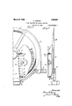
- Fig. 1 is a front elevation of a portion of 'a'slici'ng machine showing a deflector made accordingto the present invention applied thereto; 1 a 1 i Fig. 2 is aside. elevation looking from the right'in Fig. l; 7 p
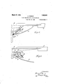
- F ig. 3. is a topv plan .view of the deflector shown in Figs. ,1 and 2; and V v Fig. 4 is a plan view similar to Fig. 3 but showing the deflector insectionand moved to inoperative position.
- the numeral 10 designates thepedestal or chain box' of a slicing machine having a ⁇ rotary slicing knife 11 journaled thereon; the knife being provided with the usual guard 12: and slice support 13.
- a deflector "14c is disposed ad- "jacent the face'of the knife 11 in position to direct the slices away from the knife'as they are severed. The deflector is in the,
- bracketlfi is secured to the side of 'thechain box 10 and hasiearsi17 and 18 at the top. and bottom respectively. thereof.
- Thebracket 16 also carriesa flange 19 have ing a socket member 20 supported thereon.
- a tongue 27 projects from the plate 20 and supports a pin 28 ofa size to fit in asocketj 29 in -the socket member 20; 'When the parts are in the position shown" 7. in Fig. 4,'the deflector is'free to swing about the ⁇ axis of the studs 24: toward and away cleaning or other purposes. When the deflector is 'swung inwardly toward the knife,
- the end of the'pin 28 will register-[with the opening 29, and the deflector may "then be "moved in the direction of the axis of the opening 29 to cause'the pin to enter the opening and take the position shown in Fig. 3.
- the open ing 29 is at slight angle [to the direction of'the slots 26'and that the slots 26' are slightly curved.
- the tongue 27 is of spring hold thestuds243 against the, inner walls of'the'slots 26.
- thisspring ten- "sion will, resiliently lock the studs 2 1; due "to the'curvatureof the slot softhat the parts will beheld in position.
- Before'the outer edge ofthe'deflector' 15 can be moved away from-the face of the knife; it will be necessary' to move the deflector forwardly to clear the. pin 28 from; the opening 29.
- The'deflector 15 has a flange 80 at its rear edge'which overlaps a shoulder 31 on the chain box 10 when the deflector is'in its locked position.
- the deflector is drawn forwardly to free the pin 28 from' the socket 29,'the'flange 30 will be moved away from the shoulder on the chain box to permit .the deflector to swing upon its p votal support.
- the flange 30 overlaps the edge of tlie chain box and prevents any gap between the rear edge of the defiec operable by movement of the deflector in the direction of movement of slices severed by said knife-forlocking said deflector in position adjacent the face of the knife.
Landscapes
- Life Sciences & Earth Sciences (AREA)
- Forests & Forestry (AREA)
- Engineering & Computer Science (AREA)
- Mechanical Engineering (AREA)
- Mechanical Treatment Of Semiconductor (AREA)
Description
F511;: oct. 14. 1926 2 Sheets-Sheet 1 March 27, 1928.
1 ,663,643 H.- THOMAS SLICE nnmcron FOR smcme MACHINES Filed Oct .-14, 192s 2 Sheets-Sheet 2 fiaezzzkr I Patented Mar. 27, 1928,
"HENRY THOMAS, or ronnon, ,nlvs'rinnn-Afssrenon Too. s. smc'mamcmmcom'.
IPANY, or LA roars, INDIANA, nconronArroiv or INDIANA.
SLIGE DEFLEGTOR Eon 'snrorne MACHINES.
Application filed October 14, 1926, Serial No.
' 5 deflectors of this nature whioh'will hold the deflectori-n position adjacent the face 'of-the slicing knife and willfnot be movedoutof "position by the slices engaging the edge of the deflector. 7 'A'further object is to provide a deflector which is locked in. operative position and in which the force of'the slices as'they'are being cut tends to hold the deflector in its locked'positio n.
r A. further object is to provide a' deflector "which will overlap its support when in operative position-to prevent any gap or open space between thedeflector and support. vT I Other objects will appear from the 'following description. V i The inventionis exemplified in the com bination and arrangementof' parts shown in the accompanying drawingsanddescribed in the following' specification, and it is'more particularly pointed out in the appended claims. I
LIn the drawings Fig. 1 is a front elevation of a portion of 'a'slici'ng machine showing a deflector made accordingto the present invention applied thereto; 1 a 1 i Fig. 2 is aside. elevation looking from the right'in Fig. l; 7 p
F ig. 3. is a topv plan .view of the deflector shown in Figs. ,1 and 2; and V v Fig. 4 is a plan view similar to Fig. 3 but showing the deflector insectionand moved to inoperative position. Inv the drawings, the numeral 10 designates thepedestal or chain box' of a slicing machine having a} rotary slicing knife 11 journaled thereon; the knife being provided with the usual guard 12: and slice support 13. A deflector "14c is disposed ad- "jacent the face'of the knife 11 in position to direct the slices away from the knife'as they are severed. The deflector is in the,
formof a plate having its forward edge 15 curved vto fit against'the face of the knife 11. A. bracketlfi is secured to the side of 'thechain box 10 and hasiearsi17 and 18 at the top. and bottom respectively. thereof. Thebracket 16 also carriesa flange 19 have ing a socket member 20 supported thereon.
141,434, and-in Great Britain March 13.1926 1 A plate21 is secured to theinner face of the deflector 15 and has ears 22 and 23 at'the top and bottom respectivelyjthereof. Studs 24 and ;25; are thread'edinto the ears 22 and '28 and project into'slots26 in the ears=17 and 18. Thisprovides pivotal support-for 1 the deflector 15. A tongue 27 projects from the plate 20 and supports a pin 28 ofa size to fit in asocketj 29 in -the socket member 20; 'When the parts are in the position shown" 7. in Fig. 4,'the deflector is'free to swing about the {axis of the studs 24: toward and away cleaning or other purposes. When the deflector is 'swung inwardly toward the knife,
the end of the'pin 28will register-[with the opening 29, and the deflector may "then be "moved in the direction of the axis of the opening 29 to cause'the pin to enter the opening and take the position shown in Fig. 3. It will be noted that the open ing 29 is at slight angle [to the direction of'the slots 26'and that the slots 26' are slightly curved. The tongue 27 is of spring hold thestuds243 against the, inner walls of'the'slots 26. As'the studs 24 move'to the rear endsof the slots, thisspring ten- "sion will, resiliently lock the studs 2 1; due "to the'curvatureof the slot softhat the parts will beheld in position. Before'the outer edge ofthe'deflector' 15 can be moved away from-the face of the knife; it will be necessary' to move the deflector forwardly to clear the. pin 28 from; the opening 29. It
will be apparent that the force of the slices againstqthe edge of {the deflector tends to move'the pin 28 into the opening 29 and thus prevents unlockingof the deflector.
j from the slicing knife 111 {When the deflec tor is swung outwardly, as illustrated inthat figure-, the face of, theiiknife is exposed for "The'deflector 15 has a flange 80 at its rear edge'which overlaps a shoulder 31 on the chain box 10 when the deflector is'in its locked position. When the deflector is drawn forwardly to free the pin 28 from' the socket 29,'the'flange 30 will be moved away from the shoulder on the chain box to permit .the deflector to swing upon its p votal support. When the deflector is in position againstthe faceof the knife and. the
1 2. The combination with a slicing knife,
' ofadeflector for protecting the face ofs aid knife, a pivotal; support for said deflector, and a. locking means operable by movement ,ofsaid deflcctoraway from theedgeof said ,knife'forf locking said deflector against movenelltupon its pivotal support. 7
3. The combination with a slicing knife, of a defiectorfor saidknife, a pivotaksupport, forsaiddeflector', said deflector being mounted to .,swing upon ,its pivotal support '?*n.dt9;mQ QTbQd\ y i th irec ion of move- 511 91 of l es sever d Y said-knife toward and away from the edge of said knife, and mean f r locking sai eflect gainst v=pi f a 1 9Wfitme t W n sai d fl t r i i oneposition of its bodily movement but per- ;mitting pivotal movement of said deflector whensaidjdeflector is in a diiferentposition d te t the edge sa d kn The combination with a slicing knife, of a defleotor for said knife, a pivot and slot .S1 ,pport for said deflector, and a spring 100k fonholding the pivot of said support in one position relative to. the slots for said pivot anld for preventing said deflector ,from ro- ,tation, upon its pivot when in said position.
5. The combination with a slicing knife, ,of a deflector for said knife, a pivotalfsupport ,forsaid deflector, a member having a slot theigein fpr receiving said pivotal sup- .pe t a n rmit e Said defl cto an support .to move -in the direction ofsaid slot {toward and from the cuttingedge of said andflalock for said deflector against rotation upon its pivotal support said deflector is at. the limit of its 50.
movement away fromnthe cutting edge of ,said knifebut permittingsaid deflector to be rotated upon its pivotal support when said deflector is movedtoward the cutting edge of saidknifeto releasesaid lock.
The combination with a slicing knife of defiector'f or'said knife,.and a :lO-Ok for. holdingfsaid deflector in position relative :to said merma d lock comprisinga pin and sqck'et ,arrang ed to engage each other Iyvl en aid de flector is in position adjacent the face o saidfknifeand moved away from the edge of saiidlk'nife;
' 7 The combination with .aslicing knife, of a, deflector for said knife, a pivotal support for said deflector shiftable with said said d fle r to mo e raes crss yfl o deflector toward. and away from the cutting edge of said knife, and a lock for holding said deflector against pivotal movement relative to said knife, saidlock being moved into holding position by movement of said deflectrans e s to he a s of sai auppe ftfln Pi and s ck members for hol g said deflecto aga ns p v ta m 1mb whim i on pQ i iQ o e o -.sa .n m e i h me m unte upon sa d p ng ongu 9- he combi ation w th S icing knife,
0 1a d flec f r sa dlm fe, a pi otal $111 port for said deflector arranged to permit ax ofsaid pivot-a pp- 1ft, 19 i an iseeke n mhs s .mevab e nto and ,f ct'fif eng ge mea with each o h .vhens d defl ctor i moved relative to its pivotal support, ,a
sp i vcennec ing e o a d mem w s i d flecto and mean i for gu din spring underhstrain when said deflector is o e ebri said-p l a asecke memb s s r er nc din -o e t a m mber i w th. s dd fi te sa dr n a d s ket anembe r'a'cting to place said spring undertension whennwved nto engagem n ith ea h other to cause said pivot to bind in its slot to hold said pinand, socket member together. i
' 11. The combination with slicing knife, of a deflector forsaidknife, a support for Sa d defle or; and m an for pivotally mounting said deflector ggnsaid support, 531d mounting ,rneans permitting movement said deflector in ea directiqn to {place lots ofIsa-id deflector relative to it s lpivotal support to bring said deflectorinto-position vto overlap said support and close 'the joint .therebetween.
12- Thelc m i ti n Wi a li ng ilm fe,
. of a deflector for 'saidlknife, a siipportjfor fsaid. deflector, a bracket .on sai d support,
[pivot and slot connections between saiddefl v r nd b a k and me n fp otking "said deflector in pos ition ad iacent. said slid s kn fe, a .d fle t r e e cved t v .lap p vh eqk po' tiwa jacent said slicing knife.
"13. Theflcoinbi ation w th a slicing knife,
,ofad ec for a knife? a suppo -fe said deflector, a bracket having pivot and slot connections with said deflector for mounting said deflector on said support, a pivot and slot connection between said bracket and deflector permitting said deflector to move bodily toward and from the cutting edge of said knife, and spring means for locking said deflector against pivotal movement when at the limit of its position away from the cutting edge of said knife, said deflector having a portion thereof arranged to overlap the support for said deflector when in said position In testimony whereof I have signed my name to this specification on this 14th day
Applications Claiming Priority (1)
| Application Number | Priority Date | Filing Date | Title |
|---|---|---|---|
| GB1663643X | 1926-03-13 |
Publications (1)
| Publication Number | Publication Date |
|---|---|
| US1663643A true US1663643A (en) | 1928-03-27 |
Family
ID=10887912
Family Applications (1)
| Application Number | Title | Priority Date | Filing Date |
|---|---|---|---|
| US141434A Expired - Lifetime US1663643A (en) | 1926-03-13 | 1926-10-14 | Slice deflector for slicing machines |
Country Status (1)
| Country | Link |
|---|---|
| US (1) | US1663643A (en) |
Cited By (1)
| Publication number | Priority date | Publication date | Assignee | Title |
|---|---|---|---|---|
| US10940602B2 (en) * | 2017-12-05 | 2021-03-09 | Marel Meat B.V. | Food singulator apparatus |
-
1926
- 1926-10-14 US US141434A patent/US1663643A/en not_active Expired - Lifetime
Cited By (1)
| Publication number | Priority date | Publication date | Assignee | Title |
|---|---|---|---|---|
| US10940602B2 (en) * | 2017-12-05 | 2021-03-09 | Marel Meat B.V. | Food singulator apparatus |
Similar Documents
| Publication | Publication Date | Title |
|---|---|---|
| US2110194A (en) | Package opener | |
| US1663643A (en) | Slice deflector for slicing machines | |
| US2355542A (en) | Hinge | |
| US1466464A (en) | Combination blade extension and wing for road machines | |
| JPS5881166A (en) | Protective device for cylinder, which is mutually reversed, of printer | |
| US2197824A (en) | Door sealing means | |
| US2031683A (en) | Rotary reducing machine | |
| US2114935A (en) | Towel dispensing cabinet | |
| US884219A (en) | Bias-fold cutter. | |
| US1286831A (en) | Crushing-mill. | |
| US1986633A (en) | Single staying machine cutter | |
| JPS6221328Y2 (en) | ||
| US1949548A (en) | Bag corner sewing machine | |
| US2370474A (en) | Mount for rotary card index boxes and filing cabinets | |
| US1185155A (en) | Ensilage-cutter. | |
| US1126542A (en) | Envelop-opener. | |
| US1703738A (en) | Envelope-opening machine | |
| US1493354A (en) | String cutter | |
| US2779362A (en) | Safety lock for cutter head of jointer | |
| US1629793A (en) | Ledger-plate fastener for guard fingers | |
| US2727775A (en) | Hatch cover lock | |
| US907617A (en) | Trimming-cutter. | |
| US2902000A (en) | Glue head for corrugated board box folding machine | |
| US1127126A (en) | Plate-finishing machine. | |
| US2755836A (en) | Comminuting chopper having a rotatable feed screw |