US1663507A - Process of preparing a dry gaseous fuel mixture for internal-combustion engines - Google Patents
Process of preparing a dry gaseous fuel mixture for internal-combustion engines Download PDFInfo
- Publication number
- US1663507A US1663507A US129193A US12919326A US1663507A US 1663507 A US1663507 A US 1663507A US 129193 A US129193 A US 129193A US 12919326 A US12919326 A US 12919326A US 1663507 A US1663507 A US 1663507A
- Authority
- US
- United States
- Prior art keywords
- mixture
- vaporization
- screens
- liquid
- equilibrium
- Prior art date
- Legal status (The legal status is an assumption and is not a legal conclusion. Google has not performed a legal analysis and makes no representation as to the accuracy of the status listed.)
- Expired - Lifetime
Links
- 239000000203 mixture Substances 0.000 title description 77
- 239000000446 fuel Substances 0.000 title description 68
- 238000002485 combustion reaction Methods 0.000 title description 23
- 238000000034 method Methods 0.000 title description 23
- 230000008569 process Effects 0.000 title description 5
- 230000008016 vaporization Effects 0.000 description 70
- 238000009834 vaporization Methods 0.000 description 64
- 239000007788 liquid Substances 0.000 description 63
- 239000008246 gaseous mixture Substances 0.000 description 20
- 239000010408 film Substances 0.000 description 17
- 238000010438 heat treatment Methods 0.000 description 16
- 239000002245 particle Substances 0.000 description 12
- 239000007789 gas Substances 0.000 description 9
- 230000000694 effects Effects 0.000 description 7
- 230000008901 benefit Effects 0.000 description 6
- 230000008602 contraction Effects 0.000 description 5
- 238000009835 boiling Methods 0.000 description 4
- 238000012986 modification Methods 0.000 description 4
- 230000004048 modification Effects 0.000 description 4
- 239000000047 product Substances 0.000 description 4
- 230000015572 biosynthetic process Effects 0.000 description 3
- 238000004508 fractional distillation Methods 0.000 description 3
- 229910052751 metal Inorganic materials 0.000 description 3
- 239000002184 metal Substances 0.000 description 3
- UGFAIRIUMAVXCW-UHFFFAOYSA-N Carbon monoxide Chemical compound [O+]#[C-] UGFAIRIUMAVXCW-UHFFFAOYSA-N 0.000 description 2
- 230000009471 action Effects 0.000 description 2
- 238000013019 agitation Methods 0.000 description 2
- 229910002091 carbon monoxide Inorganic materials 0.000 description 2
- 238000009833 condensation Methods 0.000 description 2
- 230000005494 condensation Effects 0.000 description 2
- 230000001276 controlling effect Effects 0.000 description 2
- 238000005474 detonation Methods 0.000 description 2
- 239000008240 homogeneous mixture Substances 0.000 description 2
- 230000006872 improvement Effects 0.000 description 2
- 230000001788 irregular Effects 0.000 description 2
- 230000007775 late Effects 0.000 description 2
- 238000002156 mixing Methods 0.000 description 2
- 230000002093 peripheral effect Effects 0.000 description 2
- 239000010409 thin film Substances 0.000 description 2
- 238000009827 uniform distribution Methods 0.000 description 2
- OKTJSMMVPCPJKN-UHFFFAOYSA-N Carbon Chemical compound [C] OKTJSMMVPCPJKN-UHFFFAOYSA-N 0.000 description 1
- RYGMFSIKBFXOCR-UHFFFAOYSA-N Copper Chemical compound [Cu] RYGMFSIKBFXOCR-UHFFFAOYSA-N 0.000 description 1
- 238000010521 absorption reaction Methods 0.000 description 1
- 230000033228 biological regulation Effects 0.000 description 1
- 229910052799 carbon Inorganic materials 0.000 description 1
- 238000005266 casting Methods 0.000 description 1
- 238000006243 chemical reaction Methods 0.000 description 1
- 230000000052 comparative effect Effects 0.000 description 1
- 230000006835 compression Effects 0.000 description 1
- 238000007906 compression Methods 0.000 description 1
- 230000001143 conditioned effect Effects 0.000 description 1
- 239000004020 conductor Substances 0.000 description 1
- 229910052802 copper Inorganic materials 0.000 description 1
- 239000010949 copper Substances 0.000 description 1
- 230000007423 decrease Effects 0.000 description 1
- 238000000151 deposition Methods 0.000 description 1
- 238000010586 diagram Methods 0.000 description 1
- 238000010790 dilution Methods 0.000 description 1
- 239000012895 dilution Substances 0.000 description 1
- 230000003292 diminished effect Effects 0.000 description 1
- 230000008030 elimination Effects 0.000 description 1
- 238000003379 elimination reaction Methods 0.000 description 1
- 238000002474 experimental method Methods 0.000 description 1
- 230000002349 favourable effect Effects 0.000 description 1
- 239000007792 gaseous phase Substances 0.000 description 1
- 238000003780 insertion Methods 0.000 description 1
- 230000037431 insertion Effects 0.000 description 1
- 238000009533 lab test Methods 0.000 description 1
- 239000012263 liquid product Substances 0.000 description 1
- 239000000314 lubricant Substances 0.000 description 1
- 238000012423 maintenance Methods 0.000 description 1
- 238000004519 manufacturing process Methods 0.000 description 1
- 239000012071 phase Substances 0.000 description 1
- 230000001737 promoting effect Effects 0.000 description 1
- 230000001105 regulatory effect Effects 0.000 description 1
- 239000007787 solid Substances 0.000 description 1
- 241000894007 species Species 0.000 description 1
- 239000000126 substance Substances 0.000 description 1
- 238000012360 testing method Methods 0.000 description 1
Images
Classifications
-
- F—MECHANICAL ENGINEERING; LIGHTING; HEATING; WEAPONS; BLASTING
- F02—COMBUSTION ENGINES; HOT-GAS OR COMBUSTION-PRODUCT ENGINE PLANTS
- F02M—SUPPLYING COMBUSTION ENGINES IN GENERAL WITH COMBUSTIBLE MIXTURES OR CONSTITUENTS THEREOF
- F02M1/00—Carburettors with means for facilitating engine's starting or its idling below operational temperatures
-
- F—MECHANICAL ENGINEERING; LIGHTING; HEATING; WEAPONS; BLASTING
- F02—COMBUSTION ENGINES; HOT-GAS OR COMBUSTION-PRODUCT ENGINE PLANTS
- F02M—SUPPLYING COMBUSTION ENGINES IN GENERAL WITH COMBUSTIBLE MIXTURES OR CONSTITUENTS THEREOF
- F02M2700/00—Supplying, feeding or preparing air, fuel, fuel air mixtures or auxiliary fluids for a combustion engine; Use of exhaust gas; Compressors for piston engines
- F02M2700/43—Arrangements for supplying air, fuel or auxiliary fluids to a combustion space of mixture compressing engines working with liquid fuel
- F02M2700/4302—Arrangements for supplying air, fuel or auxiliary fluids to a combustion space of mixture compressing engines working with liquid fuel whereby air and fuel are sucked into the mixture conduit
- F02M2700/434—Heating or cooling devices
- F02M2700/4342—Heating devices
- F02M2700/4345—Heating devices by means of exhaust gases
-
- Y—GENERAL TAGGING OF NEW TECHNOLOGICAL DEVELOPMENTS; GENERAL TAGGING OF CROSS-SECTIONAL TECHNOLOGIES SPANNING OVER SEVERAL SECTIONS OF THE IPC; TECHNICAL SUBJECTS COVERED BY FORMER USPC CROSS-REFERENCE ART COLLECTIONS [XRACs] AND DIGESTS
- Y10—TECHNICAL SUBJECTS COVERED BY FORMER USPC
- Y10S—TECHNICAL SUBJECTS COVERED BY FORMER USPC CROSS-REFERENCE ART COLLECTIONS [XRACs] AND DIGESTS
- Y10S261/00—Gas and liquid contact apparatus
- Y10S261/45—Processes carburetors
Definitions
- PROCESS F PREPARING A DRY GASEOUS FUEL MIXTURE FOR INTERNAL-COMBUSTION ENGINES.
- This invention relates more particularly to an improved process or method for ⁇ producing a homogeneous dry gaseous mlxture from liquid fuels and air, by equilibrium vaporization in the intake system of internal combustion engines.
- the method of producing a superheated dry gaseous mixture and o erating an engine thereon is the invention of) William P. Depp, and a more complete description of his method and apparatus will be found in his Patents No. 1,335,665, of March 30, 1920, and No. 1,360,098 of November 23, 1920. These patents are the first to describe a method of complete vaporization with the production of a superheated dry gaseous mixture under equilibrium conditions.
- the object of my improvement is to provide an improved method of equilibrium vaporization, whereby a more 'compact apparatus maybe employed to effect complete vaporization with minimum -superheating of the mixture, high rate of vaporization, at the same time providing for uniform distribution to all the cylinders of the engine of a completely homogeneous dry gaseousl mixture.
- liquid fuels should beicompletely vaporized in the intake system and so conditioned and passed through suit ably heated conduits as to remain dry and gaseous during and after introduction into the engine cylinders, for it is obvious that complete combustion is assured only when the reaction takes place between gases or gaseous substances, in proper ratios.
- a completely dry homogeneous gaseous mixture may be subjected to -higher compression pressures than a wet mixture, and, while promoting uniform combustion, decreases the tendency of knocking or so-called detonation.
- equilibrium vaporization is the complete volatilization 'of liquids maintained in such intimate relation at every step with all the vapors from the liquids that throughout the process or, as in the present instance, until complete vaporization results, all the vapors from the liquids remain in equilibrium with all of the unvaporized liquids.
- the oint of comlete vaporization of liquid fue s under equiibrium conditions is the same as the dew point or the point of initial condensation of the vaporized fuel. 4The dew point or point of condensation which corresponds to the boiling or vaporization point, is the lowest temperature ⁇ at which the liquid fuels can be ⁇ completely vaporizcd.
- This complete gaseous mixture is the ideal form in which to distribute the fuel; it will burn perfectly so that no liquid fuel is left, and carbon monoxide and other undesirable products are avoided; its perfect and smooth combustion diminishes so-called detonation, and no liquid fuel particles are added to the lubricant.
- any suitable means may be employed for accomplishing my improved method for the equilibrium vaporization of complex motor fuels, such as present day commercial gasoline, in the intake system of internal combustion engines.
- this means consists in the employment of la succession of spaced metallic screens or foraminated members placed across and adapted to intercept the entire current of air and motor fuel in the intake system, for transversely filming the liquids in the air stream at a multi licity of points, the screens being in meta lic contact with heated walls of the mixture conduit.
- Such metallic foraminated members may consist of wire mesh, grids, perforated lates, or rods closely spaced.
- Screens of t is character, therefore, are adapted to supply heat to the stream of mixture, and to filmed liquid particles, at a multiplicity-of points across the entire line of mixture flow and thus provide the most efiicient means for transversely filming and vaporizing the liquid fuels and heating the mixture throughout its mass.
- the peripheral edges of the foraminated members are preferably in heat conducting engagement with the walls of the intake conduit so that heat is most efficiently' transmitted by conduction from the walls of the conduit through the screens to liquid films formed thereon and to the stream of fuel and air, to a sufficient extent to complete the vapo'rzation.
- metallic screens may -be cast integrally with the mixture conduit walls in order to provide maximum heat conductance.
- the supply of heat being preferably just sufficient to raise the temperature of the liquid fuels above their partial pressure boiling points in the air ratio existing in the intake system.
- the supply of heat may vary with vapor- A controlled supply of heat ization demands and with varying openings of the throttle, it should be so controlled that the temperature vof the air-fuel mixture is never suflicient to crack the liquid fuels.
- the plurality of metallic screens have the ladditional advantage of atomizing the liquids and mixing the air and liquid fuels and their vapors, thereby causing turbulence and eddying as the current makes spaces behind these screens of irregular and diminished pressure. It will be understood that agitation and thorough mixing, by which the liquid and vapor and air are kept in intimate relation while heat is applied, is one of the necessary conditions for accomplishing equilibrium vaporization.
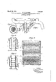
- FIG. 1 shows an arrangement of intake and exhaust manifolds in close juxtaposition, with the intake manifold riser jacketed and provided with screens for transverse filming;
- Fig. 2 shows a crosssection of the jacketed portion of the intake manifold on the line 2-2 of Fig. 1;
- Fig. 3 shows a crosssection of the jacketed portion of the intake manifold on the line 2-2 of Fig. 1;
- Fig. 4 is a sectional view of a modification employing rods or wires
- Fig. 5 is another modification wherein the screens are formed as perforated plates.
- the ordinary type of exhaust manifold is represented at 1 and the intake manifold at 2, both of which are shown as adapted for the ordinary four-cycle internal combustion engine.
- the intake manifold 2 is located above the exhaust manifold l, and so arranged that convection currents and conduction may be utilized for heating the intake manifold to maintain and deliver the mixture to the engine as afsup'erheatcd dryb gaseous mixture.
- the riser portion 3 of the intake manifold is preferably slightly enlarged, as indicated in the drawings to give sufficient cross sectional areas, in the restricted sections, produced by the insertion of a plurality of metallic screens 4, having their edges embedded in the walls of the' intake conduit, as indicated at 5 in Fig.
- the screens 4 may be of fine mesh Woven wire, as indicated in Figs. l and 3; or ⁇ closely spaced rods or wires, having their ends embedded in the walls of the conduit, as indicated in Fig. 4; or perforated v(foraminated) sheet metal, ⁇ as shown in Fig. 5.
- These screens or foralninous members may be formed of metal, lpreferably copper, which is a good conductor of heat, and as many of such screens may be employed as is found desirable. In the present instance, satisfactory results have been obtained by employing iive screens, as indicated in the drawings, spaced apart about 5% of an inch.
- the number of screens is not limited and may be two, three or as many more as may be required.
- the open spaces in the screens may be substantially equal in area to the desired cross sectional area for the intake manifold of the engine with which the apparat-us is to be employed.
- the open space is about 5
- the lower end of the riser is provided with a flange 6, cooperating with a-fiange 7 on the carburetor 8, for securing the latter in cooperative relation with the intake manifold.
- the usual throttle valve represented at 9, is provided for controlling the admission of the mixture of air and li uid fuels to the riser of the intake manifolc It has been previously ointed out that, during the operation of t e engine, as the mixture lso from the carburetor is drawn through the intake manifold by suction, the screens 4, being arranged in the path of the mixture iow, are adapted to catch and retain, by adhesion, liquid particles carried along in the air mixture.
- the riser section 3 of the intake manifold is surrounded by a jacket 10 which is connected by means of a conduit or pipe 11 with the exhaust manifold 1, so that the riser section 3 may be heated, the jacket being provided with an outlet at 12, for escape of the exhaust gases after they have passed through the jacket.
- close metallic connections between the screens 4 and the heated wall 3 of the riser conduit is essential and this is preferably obtained by casting the peri heral edges of the screens into the walls o the conduit, as shown in Fig. 3. Therefore, since the walls of the conduit are heated by the exhaust gases passin through the jacket 10, the screens 4 will e uniformly heated by direct conduction of heat thereto from the walls of the conduit.
- Fig. 3 As indicated graphically in Fig.
- the spacing between the screens 4 will permit alternate expansion of the mixture passing through the successive screens ⁇ and hence the mixture is subjected to alternate contraction and expansion as indicated by the converging and diverg ing lines in Fig. 3. Furthermore, since the screens are heated, as previously pointed out, the liquid films formed transversely on the successive screens will be heated, as well as the air fuel mixture, thereby vaporizing the liquid fuels in the presence of their own vapors, that is, vaporization will take place under equilibrium conditions.
- the alternate contraction and expansion effect of the mixture passing through the successive screens creates violent turbulence between the screens, thus thoroughly agitating the mixture, so that, by the time complete vaporization takes place, the mixture is thoroughly homogeneous and dry with a minimum amount of superheat.
- the temperature of the tributing condults should be maintained above, and preferably as near the dew-point or point of complete equilibrium vaporization as possible, to insure delivery to the engine of a dr mixture for maximum efficiency, but o viously, the amount of heat required and the temperature for vaporization will vary according to the throttle opening, which varies the amount of liquid fuels taken up and carried along in the mixture, as well as the effective artial pressure.
- the amount o heat in the exhaust gases increases in direct proportion to the amount of fuels consumed so that it is possible to re late the temperature of the mixture fair y closely bythe size of the orifice controlling the "flow ⁇ of exhaust gases through the pipe 11, which, as previously pointed out, is connected with the exhaust manifold 1. It is desirable, nowever, to regulatel the flow of exhaust gases throu h the connecting pipe 11, by a valve 16 an this valve may be adjusted by manual means to control the size of the orifice' intake manifo d, so as to effect the regulation according to the temperature o the aseous mixture in the dis-v mixture passing to the cylinders of the engine.
- thermostat regulator 17 The lower end of the thermostat regulator 17 is shown as connected by a lever 19 and link 20, with an arm 21 for operating the exhaust gas regulating valve 1G, so as to control the flow of exhaust gases through the jacket 10, according to the temperature of the mixture in the intake. manifold.
- the amount of heat supplied to the screens 4 will vary according to the requirements, the control being such as to maintain equilibrium vaporization conditions substantially uniform, independently of the volume of the flow to the engine.
- a modification is shown in which rods or wires QQ are mounted transversely of the conduit. the rods or Wires being unifolmly spaced apart, so as to permit the mixture to pass between them.
- Successive screens or rods or wires 9.2 are preferably located in the conduit at right angles to the rods or adjacent screens. so as to break up the mixture currents.
- the ends of the rods, as with the screens shown in Fig. 3, may be elnbedded in the walls of the conduit, so as to provide for the best heat conf'luctivity. Obviously, in this form, the liquid fuels will be filmed over the successive rods until equilibrium vaporization is completed.
- FIG. 5 Another form of apparatus is shown in Fig. 5, in which the screens 23 are formed of perforated metal or foraminated plates, the peripheral edges of which are preferably cast into the wall of the conduit, so as to insure satisfactory heat conductivity.
- t-he method of producing a homogeneous dry gaseous mixture of 'liquid fuels and air by equililnfium vaporization during the operation of the engine which comprises impregnating a moving stream of air Vvvith liquid fuel particles in predetermined ratio ⁇ to form the mixture, successively filming entrained liquid fuel particles in contiguous films transversely of the mixture stream, heating successively formed films While maintalning the fuel vapors in contact therewith unti'l complete vaporization is effected under equilibrium conditions, the amount of heat applied being such that the temperature of the resulting dry gaseous mixture is not less t-han the temperature for complete equilibrium vaporization of the fuels in the ratio involved.
- the method of producing ahomogeneous dr gaseous mixture of combustibles and alr by equilibrium vaporization during the operation of the engine which comprises impregnating a moving stream of air with atomized 'liquid fuel in predetermined ratio, filming the atomizcd liquid fuel in successive-stages in contiguous films transversely of the mixture stream, heating the successive stages of films while maintaining the fuel vapors in contact therewi h to effect vaporization under equilibrum conditions, and successively agitating the mixture in stages alternating with the heating filming stages.
- the method of producing a homogeneous dry gaseous mixture of combustibles and air by equilibrium vaporization during the operation of the engine which comprises impregnating a moving stream under reduced pressure with liquid fuels in predetermined ratio to form the mixture, filming the liquid fuels at successive stages in a multiplicity of contiguous films transversely of the mixture stream, vaporizing the liquid fuels under partial pressure equilibrium conditions by heating the films at the successive stages in the presence of all the fuel vapors, successively creating turbulence in the mixture by agitation thereof alternately with the filming heating stages, the heat applied being at uce com a temperature such as to pro ete equilibrium vaporization and to super eat the mixture to a templerature slightly above e liquid combustibles the dew point for t under thepartial pressures obtaining, then maintaining the mixture superheated for delivery to the engine.
- the method of producing a homogeneous gaseous mixture of combustibles and air'by equilibrium vaporization during the 'operation of the englne which comprises impregnating a moving stream of air with liquid fuels in predetermined ratio to form the mixture, successively depositing entrained particles of the liquid fuels in contiguous films transversely ⁇ of the direction of flow of themixture, heating the successively formed films in thepresence of all the fuel vapors ⁇ to eect vaporization under equilibrium dryconditions, agitating the mixture by alternate expanslon and contraction thereof while filming and vaporizing' the liquid fuels, the temperature and amount of heat being adapted for vaporizing the liquidfuel and 'maintaining the mixture at a tempera-V ture slightly above the dew-point for the fuel vapors and to maintain and deliver the mixture with minimum superheat.
- the method of producing a homogeneous dry gaseous mixture of combustibles and air by equilibrium vaporization during the operation of the engine which comprises impregnating a moving stream of air with liquid fuels in predetermined ratio to form the mixture, alternately contracting andy expanding the mixture stream in rapid succession, while lming entrained liquid particles in contiguous films transversely thereof, heating said mixture and the lms in the presence of all the vapors so as to effect vaporizationv under equilibrium conditions, the temperature and amount of heat being adapted to comelpte equilibrium vaporization at a temperature 'sllghtly above the dew' 7 i CERTIFICATE 0F CoRREoTIoN.
Landscapes
- Engineering & Computer Science (AREA)
- Chemical & Material Sciences (AREA)
- Combustion & Propulsion (AREA)
- Mechanical Engineering (AREA)
- General Engineering & Computer Science (AREA)
- Output Control And Ontrol Of Special Type Engine (AREA)
Description
C. E. PARSONS Marchv 20,
DRY GASEOUS FUEL MIXTURE FOR INTERNAL PROCESS OF PREPARING A M6 N2 I9 Gl N E4. Nl O l n@ A Bw mu. CF
INVENTOR afd- ATTORNEY Patented Mar. 20, 1928.
YUNITED STATES PATENT FFICE.
CHARLES E. PAnsoNs, or ENGLEWOOD, NEW JERSEY, AssIGNoR To WILLIAM P. BEPPE, or NEW Yomc, N. Y.
PROCESS F PREPARING A DRY GASEOUS FUEL MIXTURE FOR INTERNAL-COMBUSTION ENGINES.
Application led August 14, 1926. Serial No. 129,193. i
This invention relates more particularly to an improved process or method for` producing a homogeneous dry gaseous mlxture from liquid fuels and air, by equilibrium vaporization in the intake system of internal combustion engines. The method of producing a superheated dry gaseous mixture and o erating an engine thereon is the invention of) William P. Depp, and a more complete description of his method and apparatus will be found in his Patents No. 1,335,665, of March 30, 1920, and No. 1,360,098 of November 23, 1920. These patents are the first to describe a method of complete vaporization with the production of a superheated dry gaseous mixture under equilibrium conditions.
It `is well known to those skilled in the ar that in vaporizing liquid fuels in air mixtures, one is dealing with partial pressure boiling points. Furthermore, it is obviously desirable to apply the method in as compact a manner as possible and so that heat for vaporization is applied to the liquid fuel, not only by conduction in air but transversely of the mixture stream through a. multiplicity of metallic contacts throughout the gaseous mixture.
The object of my improvement, therefore, is to provide an improved method of equilibrium vaporization, whereby a more 'compact apparatus maybe employed to efect complete vaporization with minimum -superheating of the mixture, high rate of vaporization, at the same time providing for uniform distribution to all the cylinders of the engine of a completely homogeneous dry gaseousl mixture.
It is now well known that, for the best results, both as to uniform distributionand smooth operation, the liquid fuels should beicompletely vaporized in the intake system and so conditioned and passed through suit ably heated conduits as to remain dry and gaseous during and after introduction into the engine cylinders, for it is obvious that complete combustion is assured only when the reaction takes place between gases or gaseous substances, in proper ratios.
It has been repeatedly demonstrated, not only by laboratory tests, but under actual operation conditions, that complete vaporization ofthe liquid fuels, with the formation and maintenance of a homogeneous-dry at a relatively gaseous mixture, under minimum superheat conditions, provides numerous advantages in the operation of the engine. Some of these advantages may be enumerated as follows A completelydry homogeneous mixture facilitates uniform distribution to all the cylinders.
Such a mixture no-t only promotes uniform combustion but, with proper fuel to air ratio, makes for complete combustion with the elimination of carbon monoxide.
A completely dry homogeneous gaseous mixture may be subjected to -higher compression pressures than a wet mixture, and, while promoting uniform combustion, decreases the tendency of knocking or so-called detonation.
Furthermore, a completely homogeneous dry gaseous mixture, in proper ratio, will give increased fuel efficiency over a wet mixture, and, when introduced into the engine cylinders, remains completely dry and homogeneous, that is, only in the gaseous phase, hence, crank case dilution is eliminated. Therefore, complete vaporization `with a mlnimum amount of superheatingof the fuel vapors, is essential for the maximum realization of merated.
It will be understood that vaporization under equilibrium conditions must not be con, fused with wet mixture vaporization in heated manifold devices, wherein the vaporization takes place under more or less fractional distillation conditions. Such fractional vaporization conditions are found in prior art apparatus, the operation of which results in incomplete vaporization and lack of homogeneity in the mixture. Furthermore, the molecular species in such Wet mixture heating, vary from one part of the mixture to another, for, with irregular vaporization, liquid particles are carried along and nonvolatile residues formed, such as are well known under Engler flask vaporization conditions. Under these conditions, even relatively high temperatures do not completely volatilizef the liquid fuels, but tend to leave heavy liquid products and to crack portions thereof. or the fuels may be decomposed with the formation of residual products which cannot be distilled or vaporized within operation conditions, and which ultimately may be deposited as carbon or tarry the advantages just enulis products in the intake system or combustion chamber. Furthermore, such incomplete and fractional vaporization, with the high temperature required for heavy ends, results 1n a relatively low volumetric efficiency in the p enme. n the other hand, operation under e uilibrium conditions, permitting comp ete vaporization of motor fuels at a minimum temperature (hence minimum s uperheat) giving a homogeneous mixture without decom osition or residues, will not only give maximum fuel efficiency, but will result in all of the advantages previously enumerated. A homogeneous dry gaseous mixture of this character may be produced in the intake manifold during the operation of the engine,
. under equilibrium conditions, as hereinafter lto more fully described. Reference has been made to equilibrium vaporization and complete vaporization under equilibrium conditions and for this reason, it may be desirable to define equilibrium vaporization as follows :Equilibrium vaporization is the complete volatilization 'of liquids maintained in such intimate relation at every step with all the vapors from the liquids that throughout the process or, as in the present instance, until complete vaporization results, all the vapors from the liquids remain in equilibrium with all of the unvaporized liquids. The oint of comlete vaporization of liquid fue s under equiibrium conditions is the same as the dew point or the point of initial condensation of the vaporized fuel. 4The dew point or point of condensation which corresponds to the boiling or vaporization point, is the lowest temperature `at which the liquid fuels can be\completely vaporizcd.
It has been demonstrated by comparative tests o f equilibrium vaporization and fractional distillation that commercial gasoline in its own vapors without the admixture of air, can be completely vaporized by equilibrium vaporization at from 110 F. to 125 F., lower temperature than the so-called end point in Engler flask fractional distillation which, as previously pointed out, leaves a residue and, therefore, is not complete vaporization. Obviously, if equilibrium vaporization can be carried out in the intake of the engine in an air mixture at the approximate 15 to 1 ratio for complete combustion and at a minimum superheat temperature, the best possible mixture for maximum volumetric efficiency will be obtained. For example, commercial gasoline, as now sold tothe publicy can be completely vaporized in a 15 to 1 air fuel mixture at atmospheric pressure, under equilibrium conditions, at. approximately 120 F. to 130 F. Obviously, in mixtures of air and liquid fuels, vaporization will take place accordinxz to Daltons law as to partial pressures and the dew point or temperature OIF-'Bomlete 'Vaporization under eqluilibrium conitions, represents the partia pressure boiling point of the fuels in the air ratio emquilibrium vaporization 'not only Vproduces complete volatilization of the gasoline at minimum temperature but also produces a gaseous mixture so perfectly homogeneous that it represents but one phase. This complete gaseous mixture is the ideal form in which to distribute the fuel; it will burn perfectly so that no liquid fuel is left, and carbon monoxide and other undesirable products are avoided; its perfect and smooth combustion diminishes so-called detonation, and no liquid fuel particles are added to the lubricant.
Any suitable means may be employed for accomplishing my improved method for the equilibrium vaporization of complex motor fuels, such as present day commercial gasoline, in the intake system of internal combustion engines. In the present instance, this means consists in the employment of la succession of spaced metallic screens or foraminated members placed across and adapted to intercept the entire current of air and motor fuel in the intake system, for transversely filming the liquids in the air stream at a multi licity of points, the screens being in meta lic contact with heated walls of the mixture conduit. Such metallic foraminated members may consist of wire mesh, grids, perforated lates, or rods closely spaced. Screens of t is character, therefore, are adapted to supply heat to the stream of mixture, and to filmed liquid particles, at a multiplicity-of points across the entire line of mixture flow and thus provide the most efiicient means for transversely filming and vaporizing the liquid fuels and heating the mixture throughout its mass. As previously stated, the peripheral edges of the foraminated members are preferably in heat conducting engagement with the walls of the intake conduit so that heat is most efficiently' transmitted by conduction from the walls of the conduit through the screens to liquid films formed thereon and to the stream of fuel and air, to a sufficient extent to complete the vapo'rzation. In the present instance, metallic screens may -be cast integrally with the mixture conduit walls in order to provide maximum heat conductance. for heating the screens is preferably furnished by the engine exhaust gases passing through a heating jacket around the mixture conduit. the supply of heat being preferably just sufficient to raise the temperature of the liquid fuels above their partial pressure boiling points in the air ratio existing in the intake system. On the other hand, while the supply of heat may vary with vapor- A controlled supply of heat ization demands and with varying openings of the throttle, it should be so controlled that the temperature vof the air-fuel mixture is never suflicient to crack the liquid fuels.
The plurality of metallic screens have the ladditional advantage of atomizing the liquids and mixing the air and liquid fuels and their vapors, thereby causing turbulence and eddying as the current makes spaces behind these screens of irregular and diminished pressure. It will be understood that agitation and thorough mixing, by which the liquid and vapor and air are kept in intimate relation while heat is applied, is one of the necessary conditions for accomplishing equilibrium vaporization.
Droplets or minute s heres of unvaporized liquids are present, or inarily, in the intake system of an internal combustion engine operatino' on a so-called wet mixture, and these small lliquid spheres do not readily take up heat for vaporization and for this reason, they are likely to pass as liquids into the combustion chamber. In the means just referred to, the succession of metallic screens, however, catch such liquid particles, break them up, and hold them as films. Heat is thus furnished directly to minute globules, or thin films of the liquid, in which form it possess the greatest vapor tension and evaporates fastest. Suiicient heat for swift and complete vaporization is thus readily furnished directly to the liquid, which is held in a multiplicity of transverse films under conditions most favorable to volatilization. Furthermore, the liquid is kept in intimate contact with the vapor stream passing through the openings in the screen, (which are surrounded by the films) during the process of heating, so that a .condition of equilibrium is maintained therebetween.
In methods now widely used for producing equilibrium vaporization the liquid in the stream is vaporized largely by means of an absorption of heat from the air which has been heated at the walls of the conduit and which has then been stirred up with the liquid particles. Experiments show that it has been necessary, under the condition just mentioned, to heat a gasoline air mixture in the intake system of an internal combustion engineconsiderably above the vaporization or dew point in order to secure complete equilibrium vaporization in the limited areas, as a rule, available in practice.
In .carrying| out my improvement, various forms of apparatus may be employed, and in the accompanying drawings several forms areindicated. Fig. 1 shows an arrangement of intake and exhaust manifolds in close juxtaposition, with the intake manifold riser jacketed and provided with screens for transverse filming; Fig. 2 shows a crosssection of the jacketed portion of the intake manifold on the line 2-2 of Fig. 1; Fig. 3
is an enlarged sectional view, diagrammatically and graphically illustrating the action of the screens; Fig. 4 is a sectional view of a modification employing rods or wires and Fig. 5 is another modification wherein the screens are formed as perforated plates.
Referring to the drawings, the ordinary type of exhaust manifold is represented at 1 and the intake manifold at 2, both of which are shown as adapted for the ordinary four-cycle internal combustion engine. In the present instance the intake manifold 2 is located above the exhaust manifold l, and so arranged that convection currents and conduction may be utilized for heating the intake manifold to maintain and deliver the mixture to the engine as afsup'erheatcd dryb gaseous mixture. The riser portion 3 of the intake manifold is preferably slightly enlarged, as indicated in the drawings to give sufficient cross sectional areas, in the restricted sections, produced by the insertion of a plurality of metallic screens 4, having their edges embedded in the walls of the' intake conduit, as indicated at 5 in Fig. 3, to facilitate good heat conduction. The screens 4 may be of fine mesh Woven wire, as indicated in Figs. l and 3; or` closely spaced rods or wires, having their ends embedded in the walls of the conduit, as indicated in Fig. 4; or perforated v(foraminated) sheet metal, `as shown in Fig. 5. These screens or foralninous members may be formed of metal, lpreferably copper, which is a good conductor of heat, and as many of such screens may be employed as is found desirable. In the present instance, satisfactory results have been obtained by employing iive screens, as indicated in the drawings, spaced apart about 5% of an inch. The number of screens, however, is not limited and may be two, three or as many more as may be required.
It will be understood, as previously stated, that in order to provide sufficient free area for the passage of the mixture through the intake manifold riser, the latter is proportionately enlarged in diameter, so that the open spaces in the screens may be substantially equal in area to the desired cross sectional area for the intake manifold of the engine with which the apparat-us is to be employed. For instance, in a twenty nesh wire screen the open space is about 5 The lower end of the riser is provided with a flange 6, cooperating with a-fiange 7 on the carburetor 8, for securing the latter in cooperative relation with the intake manifold. The usual throttle valve, represented at 9, is provided for controlling the admission of the mixture of air and li uid fuels to the riser of the intake manifolc It has been previously ointed out that, during the operation of t e engine, as the mixture lso from the carburetor is drawn through the intake manifold by suction, the screens 4, being arranged in the path of the mixture iow, are adapted to catch and retain, by adhesion, liquid particles carried along in the air mixture. The liquid fuels thus caught will spread out, transversely of the mixture strea over the wires or lsolid portions of the Icreensbin the form of thin films, thus surrounding the innumerable minute openings of the screen with liquid films and minute particles, so as to insure intimate contact. under suitable temperature and equilibrium conditions. between the vapors and unvaporized liquid at all points within and transversely of the mixture stream. Any excess liquids from the first screen will break away and be carried by the air-vapor current and deposited on the second screen, alwa s in contact with the corresponding equili rium vapor, and so on.
The riser section 3 of the intake manifold is surrounded by a jacket 10 which is connected by means of a conduit or pipe 11 with the exhaust manifold 1, so that the riser section 3 may be heated, the jacket being provided with an outlet at 12, for escape of the exhaust gases after they have passed through the jacket. It has previously been pointed out that close metallic connections between the screens 4 and the heated wall 3 of the riser conduit is essential and this is preferably obtained by casting the peri heral edges of the screens into the walls o the conduit, as shown in Fig. 3. Therefore, since the walls of the conduit are heated by the exhaust gases passin through the jacket 10, the screens 4 will e uniformly heated by direct conduction of heat thereto from the walls of the conduit. As indicated graphically in Fig. 3, the spacing between the screens 4 will permit alternate expansion of the mixture passing through the successive screens` and hence the mixture is subjected to alternate contraction and expansion as indicated by the converging and diverg ing lines in Fig. 3. Furthermore, since the screens are heated, as previously pointed out, the liquid films formed transversely on the successive screens will be heated, as well as the air fuel mixture, thereby vaporizing the liquid fuels in the presence of their own vapors, that is, vaporization will take place under equilibrium conditions.
In the sectional diagram of Fig. 3, the action of the apparatus is graphically indicated by the lines representing the ow and the dots or small'circles representing minute spheres or particles of liquid fuels carriedV along in the air mixture. It will be noted that the air mixture below the lowermost screen.4 in Fig. 3, for instance at 13, is shown as carrying a considerable number of li uid fuel partlcles, which will be caught and. eld by the first screen 4, over the solid ond screen will be filmed on the third screen,
indicated in Fig. 3. Experience has shown that under ordinary conditions, all the liquid fuels will be completely vaporized u on passing the third screen, particularly w env the screens are maintained at a predetermined minimum temperature, that is, a temperature suflicient to complete the vaporization under equilibrium conditions, and but 'slightly above the dew point for the fuel vapors in the air mixture, thereby producing a homogeneous dry gaseous mixture with a minimum superheat, capable of giving the best possible volumetric etciency, with complete combustion.
The alternate contraction and expansion effect of the mixture passing through the successive screens creates violent turbulence between the screens, thus thoroughly agitating the mixture, so that, by the time complete vaporization takes place, the mixture is thoroughly homogeneous and dry with a minimum amount of superheat. The temperature of the tributing condults should be maintained above, and preferably as near the dew-point or point of complete equilibrium vaporization as possible, to insure delivery to the engine of a dr mixture for maximum efficiency, but o viously, the amount of heat required and the temperature for vaporization will vary according to the throttle opening, which varies the amount of liquid fuels taken up and carried along in the mixture, as well as the effective artial pressure. However, the amount o heat in the exhaust gases increases in direct proportion to the amount of fuels consumed so that it is possible to re late the temperature of the mixture fair y closely bythe size of the orifice controlling the "flow \of exhaust gases through the pipe 11, which, as previously pointed out, is connected with the exhaust manifold 1. It is desirable, nowever, to regulatel the flow of exhaust gases throu h the connecting pipe 11, by a valve 16 an this valve may be adjusted by manual means to control the size of the orifice' intake manifo d, so as to effect the regulation according to the temperature o the aseous mixture in the dis-v mixture passing to the cylinders of the engine. The lower end of the thermostat regulator 17 is shown as connected by a lever 19 and link 20, with an arm 21 for operating the exhaust gas regulating valve 1G, so as to control the flow of exhaust gases through the jacket 10, according to the temperature of the mixture in the intake. manifold. Obviously, by this arrangement, the amount of heat supplied to the screens 4 will vary according to the requirements, the control being such as to maintain equilibrium vaporization conditions substantially uniform, independently of the volume of the flow to the engine.
In Fig. 4, a modification is shown in which rods or wires QQ are mounted transversely of the conduit. the rods or Wires being unifolmly spaced apart, so as to permit the mixture to pass between them. Successive screens or rods or wires 9.2 are preferably located in the conduit at right angles to the rods or adjacent screens. so as to break up the mixture currents. The ends of the rods, as with the screens shown in Fig. 3, may be elnbedded in the walls of the conduit, so as to provide for the best heat conf'luctivity. Obviously, in this form, the liquid fuels will be filmed over the successive rods until equilibrium vaporization is completed.
Another form of apparatus is shown in Fig. 5, in which the screens 23 are formed of perforated metal or foraminated plates, the peripheral edges of which are preferably cast into the wall of the conduit, so as to insure satisfactory heat conductivity.
As previously described, it is essential not only to produce, but to maintain and deliver a superheatcd dry gaseous mixture to the combustion chambers of the engine. Therefore. in order to maintain the dry gaseous condition after the liquid fuel has been vapor-ized under equilibrium conditions, it is desirable and common practice to arrange for conduction of heat from the exhaust manifold to the intake manifold` and, as heated air tends to rise, it is preferable, as hereinbefore described, to place the .intake manifold above the exhaust manifold, in juxtaposition thereto, andyor provide con-l ducting lugs or projections across 'the intervening space at intervals.
he operation of the apparatus described for carrying out my improved method will be readil' understood from the description' given. he liquid fuels picked up and carried along in the mixture from the carburetor are successively filmed, Within and transversely of the mixture stream, on the foraminated members and subject to controlled temperature to effect vaporization in the presence of the complete vapors of the liquid fuels, so that throughout the operation, vaporization will take place under equilibrium conditions, the arrangement and application of heat being such that complete vaporization will take place at a minimum temperature. It will be mulerstood that superheating of tbe combustibles in the air mixture cannot take place until after complete vaporization and, likewise the mixture (loes not become dry until after complete vaporization of the liquid fuels. lVith equilibrium vaporization, however', as previously pointed out, it has been found possible, by operating according to my method, to produce a homegeneous dry gaseous mixture in the shortest possible time and over re'latively short length of the manifold conduit, a desirable feature with high speed operation, and when the available space for apparatus is limited?. liurtherinore, t-he mixture being maintained and delivered to the engine at a minimum superheat, insures maximum volumetric elliciency, with complete combustion and without the formation of objectionable products, thus giving the numerous advantages in operation hereinbefore referred to. f -lt will be further,understood that while l have shown several 'forms of apparatus for arrying out `my improved method, `I 'do not wish to be limited to the particular apparatus shown, for obviously, various modifications therein may be made without departing from the spirit and scope of the invention.
l. In an internal combustion engine, t-he method of producing a homogeneous dry gaseous mixture of 'liquid fuels and air by equililnfium vaporization during the operation of the engine, which comprises impregnating a moving stream of air Vvvith liquid fuel particles in predetermined ratio `to form the mixture, successively filming entrained liquid fuel particles in contiguous films transversely of the mixture stream, heating successively formed films While maintalning the fuel vapors in contact therewith unti'l complete vaporization is effected under equilibrium conditions, the amount of heat applied being such that the temperature of the resulting dry gaseous mixture is not less t-han the temperature for complete equilibrium vaporization of the fuels in the ratio involved.
2. In an internal combustion engine, the method as claimed in claim 1, in which the mixture stream is subjected to alternate expansion and contraction, the contractions thereof being coincident with the fihning heating stages.
3. In a internal combustion engine, the method of producing ahomogeneous dr gaseous mixture of combustibles and alr by equilibrium vaporization during the operation of the engine, which comprises impregnating a moving stream of air with atomized 'liquid fuel in predetermined ratio, filming the atomizcd liquid fuel in successive-stages in contiguous films transversely of the mixture stream, heating the successive stages of films while maintaining the fuel vapors in contact therewi h to effect vaporization under equilibrum conditions, and successively agitating the mixture in stages alternating with the heating filming stages.
4. The method according to claim 3 in which the heat applied to the filmed li uid fuels is maintained at a temperature suc as will effect complete vaporization under equilibrium conditions and produce and de- I -fuels in predetermined ratio to form the mixture, filming the liquid fuels in successive stages 1n contlguous films transversely of the direction of flow ofthe mixture, heating the successive films in the presence of all the fuel vapors to effect vaporization under equilibrium conditions, while expanding and agitating the mixture, in successive stages alternating with the filming heating stages, then superheating the mixture to a predetermined vtemperature and thereafter maintaining it as a homogeneous dry gaseous mixture, superheated above the dew point of the fuels, for delivery to the engine.
6. In an internal combustion engine, the method of producing a homogeneous dry gaseous mixture of combustibles and air by equilibrium vaporization during the operation of the engine, which comprises impregnating a moving stream under reduced pressure with liquid fuels in predetermined ratio to form the mixture, filming the liquid fuels at successive stages in a multiplicity of contiguous films transversely of the mixture stream, vaporizing the liquid fuels under partial pressure equilibrium conditions by heating the films at the successive stages in the presence of all the fuel vapors, successively creating turbulence in the mixture by agitation thereof alternately with the filming heating stages, the heat applied being at uce com a temperature such as to pro ete equilibrium vaporization and to super eat the mixture to a templerature slightly above e liquid combustibles the dew point for t under thepartial pressures obtaining, then maintaining the mixture superheated for delivery to the engine.
7. In an internal combustion engine, the method of producing a homogeneous gaseous mixture of combustibles and air'by equilibrium vaporization during the 'operation of the englne, which comprises impregnating a moving stream of air with liquid fuels in predetermined ratio to form the mixture, successively depositing entrained particles of the liquid fuels in contiguous films transversely` of the direction of flow of themixture, heating the successively formed films in thepresence of all the fuel vapors `to eect vaporization under equilibrium dryconditions, agitating the mixture by alternate expanslon and contraction thereof while filming and vaporizing' the liquid fuels, the temperature and amount of heat being adapted for vaporizing the liquidfuel and 'maintaining the mixture at a tempera-V ture slightly above the dew-point for the fuel vapors and to maintain and deliver the mixture with minimum superheat.
8. In an internal combustion engine, the method of producing a homogeneous dry gaseous mixture of combustibles and air by equilibrium vaporization during the operation of the engine, which comprises impregnating a moving stream of air with liquid fuels in predetermined ratio to form the mixture, alternately contracting andy expanding the mixture stream in rapid succession, while lming entrained liquid particles in contiguous films transversely thereof, heating said mixture and the lms in the presence of all the vapors so as to effect vaporizationv under equilibrium conditions, the temperature and amount of heat being adapted to comelpte equilibrium vaporization at a temperature 'sllghtly above the dew' 7 i CERTIFICATE 0F CoRREoTIoN.
Patent No. 1,663,2507. Granted March 24), 1928, to
CHARLES E. PARSONS.
It is hereby certified that above numbered patenf requirix 5, for the word "integral" read "inlenal and that the said Letters Patent should be read with this correction lierein illat the same may conform to the record of the case in the Patent l'lice.
Signed and sealed this will (lay of April, A. l). i928.
elror appears in the printed s ig correction as follows: Page 6, line I6, claim M. J. Moore, (Seal) Acting Commissioner of Patents.
pecilicatiou of thev CERTFCATE @if CRRECTON.
Patent No. 1,663,507. rz-interi iarch 2i), 1928, to
CHARLES E. PARSONS.
It is hereby certified tha error appears iie pi'inted specification of the above numbered patent requiring eerreetion as eiiews: ege 6, Eine 16, claim 5 for the word "integral" read "nternai"; and hat the seifi Letters Patent should ne read with this correction therein that the same may conform to the record of the case in the Paten ffee.
Signed and sealed this ith day ei Apri, A. i). 1928.
M. J. Moore, (Seal) Acting Commissioner of Patents.
Priority Applications (1)
| Application Number | Priority Date | Filing Date | Title |
|---|---|---|---|
| US129193A US1663507A (en) | 1926-08-14 | 1926-08-14 | Process of preparing a dry gaseous fuel mixture for internal-combustion engines |
Applications Claiming Priority (1)
| Application Number | Priority Date | Filing Date | Title |
|---|---|---|---|
| US129193A US1663507A (en) | 1926-08-14 | 1926-08-14 | Process of preparing a dry gaseous fuel mixture for internal-combustion engines |
Publications (1)
| Publication Number | Publication Date |
|---|---|
| US1663507A true US1663507A (en) | 1928-03-20 |
Family
ID=22438840
Family Applications (1)
| Application Number | Title | Priority Date | Filing Date |
|---|---|---|---|
| US129193A Expired - Lifetime US1663507A (en) | 1926-08-14 | 1926-08-14 | Process of preparing a dry gaseous fuel mixture for internal-combustion engines |
Country Status (1)
| Country | Link |
|---|---|
| US (1) | US1663507A (en) |
Cited By (5)
| Publication number | Priority date | Publication date | Assignee | Title |
|---|---|---|---|---|
| US2560220A (en) * | 1946-08-28 | 1951-07-10 | Graziano Joseph | Fuel vaporizer |
| US3537829A (en) * | 1966-05-24 | 1970-11-03 | Hivag Handels Und Ind Verwaltu | Device for reducing the content of carbon monoxide in the exhaust gases from an internal combustion engine |
| US5384074A (en) * | 1989-09-08 | 1995-01-24 | Pedersen; John R. C. | Carburetor metering system and wick |
| US5429102A (en) * | 1992-06-23 | 1995-07-04 | Anhydrous Devices, Inc. | Fuel saving device |
| WO2001098649A1 (en) * | 2000-06-20 | 2001-12-27 | Pure Energy Group, L.L.C. | Fuel handler box and method for internal combustion engines |
-
1926
- 1926-08-14 US US129193A patent/US1663507A/en not_active Expired - Lifetime
Cited By (5)
| Publication number | Priority date | Publication date | Assignee | Title |
|---|---|---|---|---|
| US2560220A (en) * | 1946-08-28 | 1951-07-10 | Graziano Joseph | Fuel vaporizer |
| US3537829A (en) * | 1966-05-24 | 1970-11-03 | Hivag Handels Und Ind Verwaltu | Device for reducing the content of carbon monoxide in the exhaust gases from an internal combustion engine |
| US5384074A (en) * | 1989-09-08 | 1995-01-24 | Pedersen; John R. C. | Carburetor metering system and wick |
| US5429102A (en) * | 1992-06-23 | 1995-07-04 | Anhydrous Devices, Inc. | Fuel saving device |
| WO2001098649A1 (en) * | 2000-06-20 | 2001-12-27 | Pure Energy Group, L.L.C. | Fuel handler box and method for internal combustion engines |
Similar Documents
| Publication | Publication Date | Title |
|---|---|---|
| US1663507A (en) | Process of preparing a dry gaseous fuel mixture for internal-combustion engines | |
| US1795037A (en) | Carbureting process and apparatus | |
| US2232413A (en) | Internal combustion engine | |
| US1335665A (en) | Internal-combustion engine | |
| US2259480A (en) | Manifold | |
| US1706845A (en) | Fuel separator and vaporizer | |
| US1610000A (en) | Vaporizer | |
| US1686610A (en) | godward | |
| US1222548A (en) | Kerosene-vaporizer. | |
| US1811540A (en) | Internal combustion engine | |
| US1506224A (en) | Carburetor for internal-combustion engines | |
| US2227462A (en) | Carubreting device | |
| US1154617A (en) | Heater for internal-combustion engines. | |
| US1307393A (en) | Fuel vaporizer | |
| US1273363A (en) | Carbureter accessory. | |
| US1452883A (en) | Vaporizer for combustion engines | |
| US1771531A (en) | Fuel-mixture forming and feeding apparatus for internal-combustion engines | |
| US1595415A (en) | Fuel vaporizer | |
| US1539963A (en) | Internal-combustion engine | |
| US1275117A (en) | Gas-engine attachment. | |
| US1344698A (en) | Carbureter and vaporizer | |
| US1444852A (en) | Fuel system for internal-combustion engines | |
| US2038031A (en) | Oil carburetor | |
| US1360098A (en) | Superheater-manifold for internal-combustion engines | |
| US1530440A (en) | Carburetor |