US1663458A - Lasting machine - Google Patents
Lasting machine Download PDFInfo
- Publication number
- US1663458A US1663458A US703905A US70390524A US1663458A US 1663458 A US1663458 A US 1663458A US 703905 A US703905 A US 703905A US 70390524 A US70390524 A US 70390524A US 1663458 A US1663458 A US 1663458A
- Authority
- US
- United States
- Prior art keywords
- last
- jaws
- margin
- nipper
- face
- Prior art date
- Legal status (The legal status is an assumption and is not a legal conclusion. Google has not performed a legal analysis and makes no representation as to the accuracy of the status listed.)
- Expired - Lifetime
Links
Images
Classifications
-
- A—HUMAN NECESSITIES
- A43—FOOTWEAR
- A43D—MACHINES, TOOLS, EQUIPMENT OR METHODS FOR MANUFACTURING OR REPAIRING FOOTWEAR
- A43D21/00—Lasting machines
- A43D21/16—Lasting machines with lasting pincers and toe- or heel-embracing wipers
-
- A—HUMAN NECESSITIES
- A43—FOOTWEAR
- A43D—MACHINES, TOOLS, EQUIPMENT OR METHODS FOR MANUFACTURING OR REPAIRING FOOTWEAR
- A43D21/00—Lasting machines
- A43D21/12—Lasting machines with lasting clamps, shoe-shaped clamps, pincers, wipers, stretching straps or the like for forming the toe or heel parts of the last
- A43D21/125—Lasting machines with lasting clamps, shoe-shaped clamps, pincers, wipers, stretching straps or the like for forming the toe or heel parts of the last with a plurality of pincers
-
- A—HUMAN NECESSITIES
- A43—FOOTWEAR
- A43D—MACHINES, TOOLS, EQUIPMENT OR METHODS FOR MANUFACTURING OR REPAIRING FOOTWEAR
- A43D21/00—Lasting machines
- A43D21/18—Lasting machines with lasting pincers and straight-acting wipers, also for forming the shank portions of shoes
Definitions
- This invention relates to the art of making footwear and more particularly to the lasting of shoes, in the broad sense of applying shoe parts to or assembling them upon 6 lasts, and is of especial value in the building of footwear comprising rubber or rubberized parts, although not wholly limited thereto.
- the present application is in part a continuation of my apphcation Serial No. 661,191, tiled l0 September 6, 1923, and the present invention, in some of its features, is an improvement upon those described and claimed in my applications Serial No. 582,884, filed August 19,1922, and Serial No. 630,796, filed April 9, 1923. f
- the general object of my present invention is to provide improved procedure and apparatus for making footwear and for similar operations. More specific objects are to provide means for automatically positioning the edge of a piece of sheet ⁇ stock such as a shoe part, and to provide means for determinately manipulating a piece of stock havingits edge so positioned, as in holding a shoe upper or the like' for the reception of a form member such as a last, and shaping the stock thereon. Further objects are to provide for the automatic assembling of a last with an annular or conoidal upper, from isolated positions, so that the two readily may be mounted, initially, upon their respective assembling means without requiring excessive care, and to provide for the application of the sole margin of the upper to an insole associated with the last, as a part of an automatic cycle of operations.
- a further object o5 is to provide for the automatic 'release of the work, and the supporting thereof in a position for convenient removal, upon the completion of such cycle of operations.
- Another object is to provide, and more particularly in 10a a lasting machine, a' nipper unit adapted automatically so to position the edge of a piece of sheet material between its own jaws as to grip its margin to a determinate depth from said edge.
- VAnother object is to provide' 10a means for applying the sole margin o an upper to the bottom face of a last or an insole thereon with a width of over-lap accurately determined by the applying means.
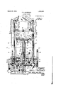
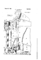
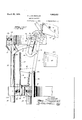
- FIG. 1 is a front elevation, partly 1n section, of a machine embodying .and adapted to carry out my invention A.m its preferred form, the work being mounted thereln and most of the nipper units being omltted for clearness of illustration. c
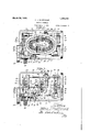
- Fig. 2 is a plan view of the machme and a shoe last therein.
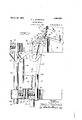
- Fig. 3 is a horizontal section on line 3-3 of Fig. 1. 0
- Fig. 4 is a side elevation of the machine as viewed from the left of Fig.'1.
- Fig. 5 is a section on line 5-5 of Fig. 3.
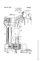
- Fig. Gis a section, on a larger scale, on line 6--6 of Fig. -3.
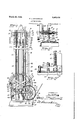
- Fig. 7 is a section on line 7--7 of Fig. 1.
- Fig. 8 is a section on line 8-8 of Fig. 1.
- Fig. 9 is a section on line 9-9 of Fig. 1.
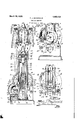
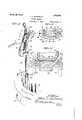
- Fig. 10 is a fragmentary, vertical section of the machine, on a large scale, showing one of the nipper units and adjacent parts in elevation, at an early stage of operation.
- Fig. 11 is a similar view of the same at a succeeding stage of operation.
- Fig. 12 is a similar view of the same at a 'still later ⁇ stage of operation.
- Fig. 13 is a perspective, detail view of one of the nipper units.
- Fig. 14 is a reverse plan view of the lastsupporting and positioning members taken on the line 14-14 of F ig. 1.
- Fig. 15 is a fragmentary, vertical section through the work and adjacent parts at the instep portion of the last.
- Fig. 16 is a fragmentary, vertical section of the apparatus, showing one of the nipper units in elevation, and representing a modified construction and mode of operation of the machine.
- each ⁇ pair of jaws will grip the margin of the lining to a determinate depth from its edge and hold it in exact position for the reception of a last, which is raised from below, through the space surrounded by a stationary, annular support upon which the nipper units are mounted, and forced into the lining so held.
- the nipper units are pivoted onf their annular support for tilting movement toward the last, against which they are adapted to bear, under the fo'rce of springs by which they are backed, to position them for a margin-a l 'n ro'ective movement of their j :ibws ulraurie1 tliellaslt, and to prevent recession of the stretched lining during such movement of the jaws.
- a lower, annular, vertically. movable frame having connection to the several ni per units, is provided for controlling their tilting movement from and toward the last,
- 10, 10 are vertical frames mounted upon a suitable base 11, and 12 is a cross-brace connecting said frames 10 near their upper ends.
- a driving shaft 13 provided with a belt pulley 14, and with a looselyjournaled pinion 15 meshed with a gear 16 secured to a countershaft 17, also journaled in the frame members 10.
- the pinion 15 is formed with a quill 15a which extends through a boss on one of the frames 10 (Fig. 5) and has a brake-drinn 18 secured to its projecting end portion.
- the end face of the quill l5a is formed with clutch teeth adapted to be engaged by complemental clutch teeth formed on a clutch member 19, secured to the shaft 13, and engaged by the forked ends of a shipper lever 20 which is secured to a short rock-shaft 21 mounted in a suitable bracket 22 on the base of the machine.
- the rock-shaft 21 is provided with a treadle 23 for operating the clutch, said treadle having an extension to which is secured a pull-spring 24 for holding the clutch f Lacasse ally extending arm 20, the intermediate portion of which is'formed with an arcuate rake-shoe 25, adapted to bear against the brake drum 18 when the clutchis. disengaged.
- a notched dog, 26 is formed on an arcuate lever 27, said lever having a pull-spring 28 connected to its free end for urging said dog normally agalnst the free end of the arm 20a, the dog being thus Iadapted automatically to engage and hold said arm after the latter has been depressed.
- the lever 27 is pivoted on a stub shaft 29 Amounted in a bracket formed on one of the frames 10, andthe hub of said lever is formed with an upwardly-extending handle 30 whereby the dog 26 may be manually released from the arm 2Oa to shift the clutch and stop the machine at any stage of its operation.
- the handle 30 is formed with a projection having a camface 30a, said projection extending into the orbit of a pin 31 proj ectinv laterally from the gear 16, said pin being adapted to engage sald cam face 30, and throw the handle 30, automatically to disengage the dog 26 from the arm 2Oa to ⁇ sto the machine after each revolution of said) gear 16, which corresponds to a complete cycle of operation of the several workmanipulating mechanisms to be described.
- a face cam 32 Secured to the shaft 17 at its end opposite the gear 16.is a face cam 32, for raising and lowering the jaw-actuatingannular frame, and at an adjacent intermediate point on said shaft is a similar but somewhat smaller face cam 33, for raising and lowering the nipper-unit-tilting frame.
- the cam 32 is adapted to actuate a cam arm 34 secured to a rock-shaft 35, the latter being journaled in, the respective frames 10.
- the cam 33 isadapted to actuate a cam arm 36 journaled on a rock-shaft 37, the latter also being journaled in the frames 10.
- the hub of the cam arm 36 is formed withl a pair of spaced-apart ears 36, 36, which straddle a radial lugformed on a collar 38 secured to the rock-shaft 37. Adjustment screws 39, 39 are threaded through the respective ears 36a and between them hold the lug of the collar 38 securely in the desired position, and make possible the angular adjustment of the shaft 37 without corresponding adjustment of the cam 33.
- the screws 39 are formed withv large knurled heads whichmay be provided with suitable markings to indicate the relative position of the -of said (Fig. 6) which has a tial positions of the nipper 'units to accommodate lasts of diierent sizes.
- crank'40 having a pair of roller Last support and elevating mecha/nimm
- a last such as 41, and an insole 42
- I provide a seat 43, the upper or seating face of which conforms to the shape of the bottom of the last, and the annular side face of which is beveled at its upper margin to provide a guiding surface 43a for the nipper jaws as the latter apply the uppers margin to the sole face of the last as hereinafter described.
- the seat 43 is mounted upon a table 44 and held against lateral movement thereon by dowel pins 44", 44, which project upwardly from said table and engage suitable apertures in a laterally adjustable plate 45, secured to the bottom seat, as is most clearly shown in Fig. 14.
- Set-screws 46, 46 are threaded through the bottom of the seat 43 to provide leveling standards for" the same, and are adapted for small vertical adjustments to compensate for variations of the lining material due to variations of temperature and humidity.
- an oval jig 47 having inwardly-extending fingers 48, 48, to be abutted by the last, is supported at its respective ends upon shouldered dowel pins 49, 49, mounted on the top of the cross-brace 12 at each end thereof. To accommodate lasts of different sizes, the seat and jig are changed.
- the table 44 is stationed, between operations, just above the cross-brace 12, being mounted on the upper ends of a pair of parallel slide bars 50, 50, which extend through a slideway in said cross-brace. Secured to the lower end portions of the respective slide bars 50 are apertured guide blocks 51, 51, embracing respective vertical,
- a chain 53 has one end secured to one of the guide blocks 51 and its other end anchored to an adjustment plate 54 slotted end engaging fiat surfaces on opposite sides of a fulcrum pin 55, and is adapted to be adjusted by means of nuts 56, 56, threaded onto the end of a stud 57 which projects through the plate ⁇ substantially at its middle, for setting the anchored end of the chain in the desired position to determine the upper limit of movement of the last.
- the chain 53 passes over a pulle 58 journaled on a cross-,head 59, said crosscad
- a pulle 58 journaled on a cross-,head 59, said crosscad
- the bottom edge face of the cross-head 59 is arcuate, on a radius equal to the effective length of the crank 40, and has a verticalv 10 slot 61 extending radially from said face,
- a plurality of upright jawcarriers or fingers 63, 63 are pivotally mounted at 63a in respective supporting pins 64, 64, said pins being mounted in a stationary, annular frame 65 which is supported by its end portions on top of the respective frame members 10.
- the shape of the frame 65 conforms generally to the peripheral contour of a shoe sole, and the ngers 63 are mounted therein at various heights to conform to the, longitudinal contour of said sole.
- the supporting pins 64 are vertically adjustable, being held by setscrews 66, to conform them to such contour.
- Each finger 63 is outwardly bent at its upper end, forming a rounded shoulder 631, adapted to rest against the last, to position the nipper unit and to prevent recession of the lining during the margin-applying operation.
- the fingers at the instep of the last are formed with their rounded shoulders at a less distance above their nipper jaws than those at other parts of the last, as shown in Fig. 15, so that they may tilt well inward under the overhanging instep ortion of the B5 last and thus engage the wor at substanto raise the shoe last 41 and insole 42 into,
- the aforesaid jaws are pivoted at 69 in the upper end of a curved lever 70, which is pivoted at 71 on' the finger 63, and has an arcuate, rearwardly-extending arm 72.
- the lower jaw 68 is formed on the under side ofits front end portion with a descending cam surface 73, and its rear end is extended beyond its pivot .and provided with a transverse stop-pin 74, adapted to coact with the outer edge of the lever 70 when the parts are in their work-receiving position, as shown in Fi s. 1, 7 and 13.
- the nose of the upper jaw 6 is sharply pointed and its rear end is bifurcated and straddles the rear extension of the aw 68, said bifurcated portion being formed with an ascending cam surface 75.
- Pivoted at 76 to the finger 63 over the nipper jaws is a doubleplate dog 77 having a roller 78 journaled at its outer end, said roller being yieldingly held against ,the upper jaw 67 by a pullspringk 79 connected at one end to the lever 70, and at the other to a U-shaped wire.
- link 80 hooked into a pair of notches on the dog 77.
- a roller 81 upon which said lower jaw normally rests and which coacts with the cam surface 73 of said jaw to produce its nipping movement.
- the respective side frames 63c are obliquely recessed at 82a on their front ed e to form a spur 82 located slightly above t e Anormal meeting plane of .the'jaws 67, 68,
- the lower end of the finger 63, adjacent its pivot, is ormed'with an outwardly-extending arm 83, adapted to be acted upon to swing the entire finger forward or backward.
- annular frame 65 Surrounding the annular frame 65 is an outer annular frame 84 in which are adjustably fixed, by means of set-screws 85a, a seriesv of vertical anchor pins 85, 85, to the respective upper ends of which are secured short lengths of chain 86, the other ends of the chains being secured to the respective arms 83 of the fingers 63, at a point relatively close to the fngers pivot 63a as to the fingers near the heel and toe of the last (Fig. l), and at a point farther from'said pivot as to the fingers at the instep ofthe last (Fig. 7).
- each arm 83 To the outer end of each arm 83 is attached the lower end of a pull- Lesa-s spring; 87 adapted to urge 'said'arm upward and t e finger 63 forward, said spring having its upper end hooked over one end of the cross-piece of a T-shaped rod 88, said rod being mounted between two such arms 83, and supporting the springs for both of them.
- the rod 88 has a conical base portion'and Yseats in a counter-sink in the frame- 84, being thus adapted for pivotal movement to compensate for the movement of the arm 83.
- the spring 87 is adapted to urge the finger 63 inwardly toward the work
- the ends of the frame 84 are ormed with respective .pairs of apertured ears 84a in whlch are secured the upper ends of respective pairs of lift-rods 89, guided in aperturediianges 10a, 10, formed on the upper ends of the respective frames 10, at opposite each pair are connected near their lower ends ⁇ by a yoke 90, and the .two yokes are loosely pivoted to studs on the free ends of a air of rocker-arms 91 mounted "on the roc -shaft 37.
- the frame 84 ⁇ is adapted to be raised or lowered by said rockshaft 37 as the latter is rocked by the-cam 33 actinl through the cam arm 36, and by means o the adjustment screws 39 above described (Fig. 8) said frame is adapted to be shifted with relation to its actuating mechanism to vary the upper-receiving ositions of the nipper units for u pers of di erent sizes.
- the chains 86 which control the upperreceiving position of the respective nipper units, being connected to the ingers -63 at points relatively close to the latters pivots, as to the nipper units at the heel and toel portions of the last and at points farther from the pivots of the fingers as to the nipper units which are at or nearer to the instep ⁇ portion of the last, as will be seen by comparison of Figs. 1 and 7, the upperreceiving positions of the ni per units will be less varied at the inste t an at the heel and toe in the adjustment just described, this being 'in accordance with the fact that lasts of different sizes vary less in width at the instep than they do in outline of the heel and toe.
- upper annular frame 94 carries a plurality of vertically-adjustable, depending rods 95, 95, fixed therein by set-screws 95, said rods having forked lower ends bent obliquely inward, and each being provided with a roller 96 journaled near the closed end of its slot.
- the slots in the respective rods 95 are adapted to receive and guide the actuating arms 72 of the respective levers 70,
- each ofthe arms 72 is such as to be substantially concentric with the pivot 63a of the finger 63 when said arm 1s 1n depressed position as shown in Fi 10, so that ⁇ the roller 96 will hold the nipper jaws closed while permitting the nipper unit to be tilted from the position of Fig. 10 to that of Fig. 11.
- the frame 94 is mounted on the upper ends of two pairs of lift-rods 99, guided in apertures in the anges 10.v
- the rods 99 of each pair are connected near their lower ends by a yoke 101 formed with apertures through which the lift-rods v89 freely pass, and the two yokes 101 are loosely pivoted to studs on the ends of a pair ⁇ of rocker-arms 102 mounted on the rock-shaft 35.
- the ⁇ frame 94 is adapted to be raised or lowered by the rock-sha t 35 asits angular position is varied by the cam 32 acting through the cam-arm 3 Operation.
- Countershaft 17 also rotates the cams and 33,' ⁇ the action of which may be noted in Figs. 8 and 9, said cams rotating counterclockwise as there viewed.y
- the oblique part A of t e groove in cam 32 moves the frame 94 downward, thereby actuating thearms 72 'of the levers 70 to Ydraw their jaws 67, 68, in a direction away from the work (see Fig. 10), the osition ofthe fingers 63 being maintaine by the chains 86 and springs 87.
- This causes said jaws lightly to close upon the margin of the shoe lining and frictionally grip the same, the jaw 67 being yieldingly held closed by the dog 77.
- the margin of the lining is thus drawn agamst the front edges ofthe respective fingers 63, causing the ⁇ jaws to slide on the fabric until, toward the end of the outward movement of said jaws, the cam surface 73 of the lower 'aw engages the roller 81, and rides upward thereon, causin said jaws to carry the margin of the lining 62 upward against the spur 82, where it is firmly held and anchored as shown in Fi 11.
- ⁇ The duration of ⁇ said anchora e is indicated by the arcuate dwell B of the groove in cam 32.
- the spur 82 acts as a third nipper jaw.
- crank 40 While the aws 67, 68 are closing upon the margin of t e lining, the action of crank 40 upon the cross-head 59, transmitted through lthe pulley 58, chain 53 and bars 50 to the last-support 43. elevates the last toward the lasting position.
- the uppers margin 1s t us stuck to the insole at a determinate distance from the edge of the latter, without requiring the tacky, cemented margin to slide u on the insole, although the retraction o the stock subsequently may cause it to draw backward past the edge of the insole in case the margin is transverselj7 slack, slippage past said edge being permitted by the absence of cement from that portion of the u pers margin.
- the latter is referably helddown by hand, to prevent t e jaws which first bear against the last from lifting it before the other jaws have been brought to bear rmly upon it.
- nipper jaws function to lift the lastat diiferent stages
- the particular manner in which the nipper jaws function to lift the lastat diiferent stages may vary according to proportions of the parts, but the particular character of the action at any stage is not of great consequence, since the units are sufficient in number and combined force to raise the last clear of the fingers 63 by either the cam or the reversed toggle action.
- the cantilever action of the upper jaws is not essential to releasing the last and' supporting it in position for convenient removal, but is primarily ma ,l
- the machine as above described is adapted to apply the margin of the upper to the 1nsole with a determinate amount of overlap by reason of the vguiding of the nipper jaws upon the last support, and I prefer thls embodiment of the invention because uniformity of the overlap may be obtained thereby notwithstanding such variations in the stock as ordinarily occur in factory practice, but
- any recession of the lining permitted by the shoulder 63h of the finger 63 during t e application of the margin may affect the amount of the latters cverlaand as the binding of the lining upon the last in theiniial stretching operation is not uniform .at all points around the latter, being less at the heel, where the pull is parallel with the last surface, and greater 'at the toe, where the lining must be pulled about a sharper contour, this mode of yoperation reuires somewhat more accurate cutting. of t e stock and adjustment of the actuating springs in order to obtain the uniformity/of product desired.I j
- a lasting machine comprising a set of nipper units completely surrounding a lasting position and adapted to receive the sole margin of an upper between their opened jaws, means for concurrently closing said jaws to hold said upper substantially throughout its perimeter, and means for relatively advancing a last from a noncontiguous position into an upper so held'.
- the'combination of a set of stock-anchorin units defining a lasting position means or determinately positioning the'edge of an upper to be held by said units, and means for relatively advancing a last in determinate relation into an upper so held, from a position non-contiguous to said upper.
- a lasting machine the combination of a set of nippers completely surrounding a lastingposition, and adapted to receive the sole margin of an upper between their opened jaws, means for concurrently closing said jaws to hold said upper substantially throughout its perimeter, means for anchoring said margin as so relatively advancing a last from a non-contiguous position into an upper so held, and means for simultaneously actuating said ⁇ nippers to cause them to apply said margin to the sole face of the last.
- a lasting machine the combination of means for holding an upper conoidally by its sole margin, means for relatively advancing a last into said upper in determinate relation from a position non-contiguous thereto, so as to draw said margin past the sole of the last, means for applying said margin to the sole face of the last, and power driven mechanism adapted, upon being started, to actuate the several said means in timed relation throughout the cycle of operations described.
- a lasting machine comprising means for supporting a last with an upper thereon having its sole margin projecting past the sole of the last, and margin-applying means adapted by non-progressive engagement with said margin to swing the latter onto the sole face of the last, the said marginapplying means comprising pairs of jaws mounted to approach the sole-tace of the last from a direction non-parallel thereto, and mountings for the respective pairs of jaws so constructedand arranged as to bear against the last to position the jaws with relation to the last.
- margin-applying means comprises a pointed member adapted obliquely to penetrate the outer face of the uppers margin.
- a lasting machine comprising means for supporting a last with an upper thereon having its margin projecting past the sole of t-he last, margin-applying means adapted by non-progressive engagement with said margin to apply the latter to the sole face of the last, and means independent of the tautness of the upper for so guiding said marginapplying means as to a ply said margin to the sole of the last with its edge at a determinate distance from the edge of the sole face of the last.
- margin-applying means comprises a pointed member adapted obliquely to penetrate the outer face of the uppers margin.
- a lasting machine comprisin a set of jaw carriers surrounding and de ning the lasting position, jaws on said-carriers adapted to anchor the margin of an upper for the reception of a last, means for holding said carriers against the last, and means for applying the margin of the upper to the sole face of the last while said carriers bear against the last.
- a lasting machine comprising a group of upper-stretchers dening a lasting position and adapted to anchor the margin of an -ieaasa upper, means for drawing the margin of the upper into engagement with said stretchers, means for determinately positioning the edge of an upper as it is received by said stretchers, a last-support, means for relatively ad- '.vancing said support so as to carry a last thereon 1n determinate relation infto an upper tion and adapted to anchor the margin of,
- an upper means for determinately positioning the edge of an upper as it is received by said stretchers, a last-support, means for relatively advancing said support so as to carrya last thereon in determmate relation into an upper held by said upper-stretchers, margin-applying means adapted to engage the margln of said upper at a determinate distance from its edge, for applying said margin to the sole face of the last, and means on said last-support for guiding said margin-applying means.
- a series of pairs of nipper jaws including lower jaws collectively forming a support for the lower edge of the upper a vertically movable last support adapte in its depressed position to receive the last, means for elevating said last support to the lasting position, and means for actuating said ni per jaws to cause them to close upon t e upper and apply its margin to the sole face of the last.
- a lasting machine comprising a group of upper-stretchers adapted to anchor the margin of an upper, means for drawing the margin of an upper edge-foremost toward said stretchers, means adapted to be abutted by the edge face of the said margin to position the latter with relation to said stretchers, and means to cause the stretchers to engage the margin as so positioned.
- a lasting machine comprising a set of nipper units adapted freely to receive the margin of an upper between their opened jaws7 means for lightly closing said jaws and moving them outwardly in sliding engagement with said margin, means adapted by stopping abutment with the edge face of the said margin to position the latter as it is thus drawn by said jaws, and means for anchoring said margin as it is so positioned.
- a lasting machine comprising a set of nipper units adapted freely to receive the margin of an upper between their opened jaws and deinitely to position the same by engagement with its edge face, means or closing said jaws upon the margin of said upper to hold the same as so ositioned, a last support, and means for e ecting such relative movement of said nipper units or said last support as to bring together in determinate relation from isolated positions a last on said support and aiiupper held by said units.
- a lasting machine comprising a set of nipper units adapted freely to receive the margin of an upper betweenvtheir opened jaws and denitely to position the same by engagement with its edge face, means for closing said jaws upon the margin of said upper to hold the same as so positioned a last support, means for effecting ⁇ such re ative movement of said nipper units and a last as to bring them together in determinate relation from isolated positions and insert the last into an upper held by said units, and means for applying the margin of said upper to the sole face of the last.
- a lasting machine comprising a set of nipper units adapted freely to receive the margin of an upper between their-opened jaws and anchor the same, a last support,
- each of said units comprising a member adapted to be abutted by the edge face of the upper determinately to position the same, a pair of jaws mounted for movement toward and from a common central position past the upper positioning face of said member, means for closing said jaws lightly upon the mar in of the upper and moving'them outwar in sliding engagement therewith to insure contact of the uppers edge with said positioning member, and means for more lirmly anchoring the uppers margin as it is positioned by said member.
- a lasting machine the combination of means for positioning a last and, cooperatively associated therewith, a nipper unit, and means for so moving the nipper unit with relation to the last as to stretch on the last an upper held by said unit, the saidunit comprising a member adapted to be abutted by the edge face of a piece of sheet material for positioning the latter, ⁇ a pair ,of jaws mounted for such relative movement as to be projected and retracted past the positioning face of said member, means for lightly closing said gripper jaws as they are so retracted, to draw ⁇ against said positioning face the edge of a piece of sheet material engaged by said jaws, and means for anchoring said piece as it is so positioned.
- the said unit comprising a member adapted to be abutted by the edge face of a piece of ⁇ sheet material for positioning the latter, a pair 01EA jaws mounted vfor such relative movement as to be projected and retracted past the positioning face of said member, means for closing ⁇ said jaws lightl upon the margin of a iece of sheet material embraced between t ein, means for retractmg said jaws 1n sliding engagement with said piece to assure contact of the latters edge with said positioning member, and meansfor more firmly closmg said jaws upon said piece as they are retracted.
- 4and means for so moving the nipper' unit with relation to the last as to stretch on the last an upper held by said unit, the said unit comprising a4 member adapted to be abutted by the edge face of a piece of sheet stock to position' ⁇ the latter, a pair of jaws mounted for such relative movement as to be projected and retracted past the positioning face of said member, and means adapted by cam action on said jaws to close the same as they are retracted and to permit them to open as they are projected, said cam means being adapted to close said jaws lightly in the first part of their retractive movement and more firmly' in the latter part of said movement.
- a lastin machine the com ination of means for positioning a last and cooperatively associated therewith, a nipper unit, and means ⁇ for so moving the mpper unit with relation to the last as to str'etch on the last van upper held by said unit, the said unit comprising a ⁇ pair of hinged jaws mounted for movement of translation, and a cam member mounted to run on one of said 'aws in front of their hinge for holding said jaws closed in a determinate range of said ⁇ movement, one of said jaws being provided at its hub with a cam surface adapted to be engaged lby the said cam member :for opening said jaws Vat one end of said range.
- nipper mechanism including a pair of jaws adapted to receive the margin of an upper between them when ⁇ the jaws are in open position, means for causing said jaws to close upon said margin and slide outwardly thereon in substantiall closed y,relation, and then to move inwardly toward the center line of the. last and then toward the .sole face of the last to carry said margin against the sole face of the last, and means' for causing the'jaws to gri the margin of the upper to a determinate epth at the end of their outward, sliding movement.
- a nipper mechanism including a pair of nipper jaws adapted for outward sliding engagement with the margins of an upper while the jaws are in substantially closed relation, means adapted to be abutted by the edge face of the upper as the latter is drawn,
- a third nipper jaw adapted to engage the edge of the upper and to anchor the same only at the limit of said outward movement, and means for imparting an inward movement of translation to said jaws while said edge is thps engaged,
- the combination vof a series f pairs of .nipper jaws surrounding the lasting position and including members adapted to support lan Yup er in conoidal form imposition ⁇ to receive a ast, ⁇ means ⁇ .for advancing a last into the upper, means for closing said jaws and moving them outwardly while so closed, and means for moving the ljaws inwardly to apply the margin. ofthe upper onto the sole face ofthe last.
- the combination of means for supporting a last in lasting osition, ⁇ azseriesof pairsof nipper jaws having opening and closing movement, ⁇ an voutward movement Aof translation ⁇ while the jaws are :substantially closed upon the ⁇ margin of an upper, andan inward movement of tranlation to carry ⁇ the edge ⁇ of ⁇ the upper onto the sole face of the last, a series of lingers carryin said jaws, each having means for positioning the upper by engagement with its edge as it is drawn outward by said jaws, means Vfor nipping the edge of the upper as it is so positioned, and means for imparting an inward movement 4tc said lingers While the edge .is thus nipped.
- a lasting machine comprising a last support and, cooperatively associated there-y wit a pivoted, nipper-supporting finger, adapted to swing from and toward the last',l a lever pivoted on ,said finger, a pair of nipper-jaws on said lever and adapted to be opened and closed by pivotal movement of said lever on said arm, said lever being formed with. a curved face adapted to be engaged. for actuating said lever to close said jaws, said face being concentric with the pivot of said finger when the jaws are closed, and meansrunning on said curved face for holding said jaws closed while permitting said finger to be turned on its pivot.
- a lasting machine as defined in claim 34 in which a yieldingly impelled dog is adapted to run on one of the jaws to urge it toward .closed position and to abut a projection on said jaw at its pivot to open said l jaw.
- a lasting machine the combination of a series of nipper units surrounding and defining the lasting position and adapted to receive the lower edge of a conoidal upper in upright posture, three annular frames connected with said'nipper units, and means for causing suitably-timed vertical movement of certain of said frames relative to each other to cause said units to grip the edge of the upper and independently of tension in the margin to'carry it onto the sole face ofthe last.
- a lasting machine the combination of a series of nipper units surrounding and defining the lasting position, a fixed frame supporting said units, a pair of vertically movable frames connected to operate said units and means for causing suitably-timed movement of said pair of frames relative to each other and to the fixed frame to cause the units to grip the edge of an upper and to carry it onto the sole face of the last.
- a nipper unit including a pair of nipping jaws having relative pivotal movement toclose them u on the upper, a
- lever adapted to project sai jaws to produce.
- a nipper 'unit including a finger pivoted for movement of its free end toward and from the last, a jawcarrying lever pivoted on said linger, a pair of nipper jaws pivoted for opening and closing movements on said lever and for projective and retractive movement with the lever relative to saidfinger, and a third nipper jaw on said finger coacting with said pair of jaws at the limit of retractive movement of the latter.
- a lasting machine the combination of means for supporting a last in the lasting position, and a nipper unit comprising a finger pivoted for movement of its free end toward and from the last, a lever pivoted 37.
- the combination wto said finger, a pair of nipper jaws mounted for pivotal movement' on said lever and for projective and retractive movement with said lever on the finger, a third nipper jaw on said finger, members on the finger and one of'said pair of vjaws for producing the nipping action of the three jaws at the limit of the retractive movement of the pair of jaws, and a dog pivoted to said 'finger and coacting with the othervone of said pair ofv jaws to open said pair at the limit of the projective movement ofthe latter.
- a series of nipper units surrounding and defining the lasting position and each comprising a fingerv plvoted for movement to ⁇ ward and from the work, a lever pivoted vto said finger, a pair of nipper jawspivoted to said lever and slidable upon the finger, and a frame 'adapted for movement relative to the series of fingers for simultaneously acting upon their levers to operate the nipper jaws.
- a series of nipper units each comprising a finger pivoted for movement toward and from the work, a movable frame having connections with the respective fingers for simultaneously producing their pivotal movements, a series of levers pivoted on said fingers, a series of pairs of nipper jaws pivoted to said levers. and slidable on said fingers, and a second movable frame having connections with the respective/levers for Simultaneously swinging them to operate the respective pairs of nipper jaws.
Description
March 2o, 192s. l 1,663,458
F. J. MacDONALD LASTING MACHINE Filed April 3. 1924 9 Sheets-Sheet 1 f4 wfg/@Mmm March 20, 1928. 1,663,458
F. J. MacDoNALD LASTING MACHINE Filed April s, 1924 9 Sheets-Sheet 2 March 20, 1928. Y 1,663,458
F. J. MacDoNALD LASTING MACHINE Filed Abril 3, 1924 9 Sheets-Sheet 3 27 fm/@UME March 2o, 192s.v 1,663,458
F. J. Ma-CDONALD LASTING MACHINE JMW/' Ewig/75M. E
F. J. MamoNALD LASTING MACHINE March 20, 1928. 1,663,458
F. J. MacDoNALD LASTING MACHINE Filed April 5. 1924 9 Sheets-Sheet 6 March 20,1928. mams@ F.`v J. MacnONALD 4 LASTING MACHINE Filed April 5, 1924 9 Sheets-Sheet 8 \..f if 63319 2 3a arch zo, 192s. MM45@ F. J. MaCDONALD LASTING MACHINE Filed April 5, 1924 9 Sheets-Sheet 9 al I 3i ff v ffm/- IIII .o G f ,a 82 )lill @4 Z3 42 IJ; 5g 68 a @j i 70 fi i @7 I\ 99 v j k im @d 64 '0i IFI 1 H M m.
\ Patented Maf. zo, 192s.
UNITED STATES PATENT OFFICE.
FRANK J. MAGDONALD, OF AKRON, OHIO, ASSIGNOR T THE B. F. 'GOODBICH COMPANY,
or Naw YORK, N. Y., .A CORPORATION 0F NEW YORK.
LASTING MACHINE.
Application led `April 3,
This invention relates to the art of making footwear and more particularly to the lasting of shoes, in the broad sense of applying shoe parts to or assembling them upon 6 lasts, and is of especial value in the building of footwear comprising rubber or rubberized parts, although not wholly limited thereto. YThe present application is in part a continuation of my apphcation Serial No. 661,191, tiled l0 September 6, 1923, and the present invention, in some of its features, is an improvement upon those described and claimed in my applications Serial No. 582,884, filed August 19,1922, and Serial No. 630,796, filed April 9, 1923. f
Numerous machines heretofore have been devised for stretching preformed or partially formed leather uppers on their lasts and applying the margin of the upper to the bottom face of an insole associated with the last, but in all such machines, so far as I am aware, the upper has required to be introduced by hand to the last or to be shifted or positioned upon the last after it is brought into contact therewith, in` order to obtain the proper relation of parts in the finished shoe. This has required skill or care and the expenditure of time, and so lfar as I am aware no such machine heretofore devised has been adapted to bring-a last and an annular or conoidal upper together in determinate relation, from isolated positions, and automatically to perform the complete lasting operation, in the broad sense, without intermediate manual control or manipulation.
It heretofore has been proposed to form a Vleather shoe by clamping a flat, watersoaked, imperforate leather blank between annular clamping members engaging its margins and to give it the forml of an upper by stretching it over a last while the blank or the last is constrained to move in a determinate path with relation to the other,
but. the leather blank has required to be.'
continuous over the shank of the last during.
the stretching operation, necessitating the later cutting out of a portion to form the ankle opening, with substantial waste. In-
termediate manual control or manipulation has been required, and the apparatus proposed is not adapted to fold under'the sole margin of the upper.
In-my applications Ser. Nos. 582,884 and 630,796 above mentioned I have described `adapted to adhere to the last or a lining 1924. Serial No. 703,905.
apparatus and procedure whereby a flat, U-shaped upper of unvulcanized sheet rubber and a last may be brought together in determinate relation from isolated positions and the upper completely applied to the last without visual gaglng or manual positioning of the stock upon the last, but the inventions of those applications have been directed more especially to the manipulation of stock thereon at al1 points of contact, which is in some respects a different problem from the manipulation of a lining or an upper adapted readily to slide and shift its position upon the last, and the operations there described have involved a considerable degree of care in the initial positioning and securing of the stock upon the members which subsequently manipulate it.
The general object of my present invention is to provide improved procedure and apparatus for making footwear and for similar operations. More specific objects are to provide means for automatically positioning the edge of a piece of sheet `stock such as a shoe part, and to provide means for determinately manipulating a piece of stock havingits edge so positioned, as in holding a shoe upper or the like' for the reception of a form member such as a last, and shaping the stock thereon. Further objects are to provide for the automatic assembling of a last with an annular or conoidal upper, from isolated positions, so that the two readily may be mounted, initially, upon their respective assembling means without requiring excessive care, and to provide for the application of the sole margin of the upper to an insole associated with the last, as a part of an automatic cycle of operations. A further object o5 is to provide for the automatic 'release of the work, and the supporting thereof in a position for convenient removal, upon the completion of such cycle of operations. Another object is to provide, and more particularly in 10a a lasting machine, a' nipper unit adapted automatically so to position the edge of a piece of sheet material between its own jaws as to grip its margin to a determinate depth from said edge. VAnother object is to provide' 10a means for applying the sole margin o an upper to the bottom face of a last or an insole thereon with a width of over-lap accurately determined by the applying means. Further objects and advantages willbeconie manifest lm in-v the vfollowing description of the preferred embodiment of my invention.
Of the accompanying drawings Fig. 1 is a front elevation, partly 1n section, of a machine embodying .and adapted to carry out my invention A.m its preferred form, the work being mounted thereln and most of the nipper units being omltted for clearness of illustration. c
Fig. 2 is a plan view of the machme and a shoe last therein.
Fig. 3 is a horizontal section on line 3-3 of Fig. 1. 0
Fig. 4 is a side elevation of the machine as viewed from the left of Fig.'1.
Fig. 5 is a section on line 5-5 of Fig. 3.
Fig. Gis a section, on a larger scale, on line 6--6 of Fig. -3.
Fig. 7 is a section on line 7--7 of Fig. 1.
Fig. 8 is a section on line 8-8 of Fig. 1.
Fig. 9 is a section on line 9-9 of Fig. 1.
Fig. 10 is a fragmentary, vertical section of the machine, on a large scale, showing one of the nipper units and adjacent parts in elevation, at an early stage of operation.
Fig. 11 is a similar view of the same at a succeeding stage of operation.
Fig. 12 is a similar view of the same at a 'still later` stage of operation.
Fig. 13 is a perspective, detail view of one of the nipper units.
Fig. 14 is a reverse plan view of the lastsupporting and positioning members taken on the line 14-14 of F ig. 1.
Fig. 15 is a fragmentary, vertical section through the work and adjacent parts at the instep portion of the last.
Fig. 16 is a fragmentary, vertical section of the apparatus, showing one of the nipper units in elevation, and representing a modified construction and mode of operation of the machine.
GenemZ description.
tween their jaws in a manner such that each` pair of jaws will grip the margin of the lining to a determinate depth from its edge and hold it in exact position for the reception of a last, which is raised from below, through the space surrounded by a stationary, annular support upon which the nipper units are mounted, and forced into the lining so held. The nipper units are pivoted onf their annular support for tilting movement toward the last, against which they are adapted to bear, under the fo'rce of springs by which they are backed, to position them for a margin-a l 'n ro'ective movement of their j :ibws ulraurie1 tliellaslt, and to prevent recession of the stretched lining during such movement of the jaws.
A lower, annular, vertically. movable frame, having connection to the several ni per units, is provided for controlling their tilting movement from and toward the last,
and a higher, annular, vertically movableA .complete cycle of lasting operations, and for stopping the machine at the end of each such cycle. Y
While I prefer to provide separate machines adapted respectively for right and left shoes, rather than to make the adjustments of one machine which would be necessary for operation upon both right and left shoes, the machine shown in the accompany ing drawings, for a left shoe, will be suliiciently illustrative,
As my invention 1s not wholly limited to the application. of a shoe lining or to the l presence of an insole on the last, the word upper will beused throughout the speci.
lication and claims as including a lining or similar upper shoe part, and the word last will be used as including an insole or an upper shoe part such as a lining associated 'with the last, as well as a bare last.
Actuatz'fng 'mecha/mism,
Referring to the drawings, 10, 10, are vertical frames mounted upon a suitable base 11, and 12 is a cross-brace connecting said frames 10 near their upper ends. J ournaled in the respective frames 10 near the base of the machine is a driving shaft 13 provided with a belt pulley 14, and with a looselyjournaled pinion 15 meshed with a gear 16 secured to a countershaft 17, also journaled in the frame members 10. The pinion 15 is formed with a quill 15a which extends through a boss on one of the frames 10 (Fig. 5) and has a brake-drinn 18 secured to its projecting end portion. The end face of the quill l5a is formed with clutch teeth adapted to be engaged by complemental clutch teeth formed on a clutch member 19, secured to the shaft 13, and engaged by the forked ends of a shipper lever 20 which is secured to a short rock-shaft 21 mounted in a suitable bracket 22 on the base of the machine. The rock-shaft 21 is provided with a treadle 23 for operating the clutch, said treadle having an extension to which is secured a pull-spring 24 for holding the clutch f Lacasse ally extending arm 20, the intermediate portion of which is'formed with an arcuate rake-shoe 25, adapted to bear against the brake drum 18 when the clutchis. disengaged. For holding the clutch 19 in its engaged position after4 the treadle 23 has been depressed, a notched dog, 26 is formed on an arcuate lever 27, said lever having a pull-spring 28 connected to its free end for urging said dog normally agalnst the free end of the arm 20a, the dog being thus Iadapted automatically to engage and hold said arm after the latter has been depressed. The lever 27 is pivoted on a stub shaft 29 Amounted in a bracket formed on one of the frames 10, andthe hub of said lever is formed with an upwardly-extending handle 30 whereby the dog 26 may be manually released from the arm 2Oa to shift the clutch and stop the machine at any stage of its operation. The handle 30 is formed with a projection having a camface 30a, said projection extending into the orbit of a pin 31 proj ectinv laterally from the gear 16, said pin being adapted to engage sald cam face 30, and throw the handle 30, automatically to disengage the dog 26 from the arm 2Oa to` sto the machine after each revolution of said) gear 16, which corresponds to a complete cycle of operation of the several workmanipulating mechanisms to be described.
Secured to the shaft 17 at its end opposite the gear 16.is a face cam 32, for raising and lowering the jaw-actuatingannular frame, and at an adjacent intermediate point on said shaft is a similar but somewhat smaller face cam 33, for raising and lowering the nipper-unit-tilting frame. The cam 32 is adapted to actuate a cam arm 34 secured to a rock-shaft 35, the latter being journaled in, the respective frames 10. In a similar manner the cam 33 isadapted to actuate a cam arm 36 journaled on a rock-shaft 37, the latter also being journaled in the frames 10. The hub of the cam arm 36 is formed withl a pair of spaced- apart ears 36, 36, which straddle a radial lugformed on a collar 38 secured to the rock-shaft 37. Adjustment screws 39, 39 are threaded through the respective ears 36a and between them hold the lug of the collar 38 securely in the desired position, and make possible the angular adjustment of the shaft 37 without corresponding adjustment of the cam 33. The screws 39 are formed withv large knurled heads whichmay be provided with suitable markings to indicate the relative position of the -of said (Fig. 6) which has a tial positions of the nipper 'units to accommodate lasts of diierent sizes.
Mounted on the counter-shaft 17 near lts middle is a crank'40 having a pair of roller Last support and elevating mecha/nimm For supporting a last such as 41, and an insole 42, I provide a seat 43, the upper or seating face of which conforms to the shape of the bottom of the last, and the annular side face of which is beveled at its upper margin to provide a guiding surface 43a for the nipper jaws as the latter apply the uppers margin to the sole face of the last as hereinafter described. The seat 43 is mounted upon a table 44 and held against lateral movement thereon by dowel pins 44", 44, which project upwardly from said table and engage suitable apertures in a laterally adjustable plate 45, secured to the bottom seat, as is most clearly shown in Fig. 14. Set- screws 46, 46 are threaded through the bottom of the seat 43 to provide leveling standards for" the same, and are adapted for small vertical adjustments to compensate for variations of the lining material due to variations of temperature and humidity. last on the seat 43 an oval jig 47, having inwardly-extending fingers 48, 48, to be abutted by the last, is supported at its respective ends upon shouldered dowel pins 49, 49, mounted on the top of the cross-brace 12 at each end thereof. To accommodate lasts of different sizes, the seat and jig are changed.
The table 44 is stationed, between operations, just above the cross-brace 12, being mounted on the upper ends of a pair of parallel slide bars 50, 50, which extend through a slideway in said cross-brace. Secured to the lower end portions of the respective slide bars 50 are apertured guide blocks 51, 51, embracing respective vertical,
fixed guide- rods 52, 52, the latter being secured at their upper ends to the cross-brace 12 and having their lower ends inset in the base 11. A chain 53 has one end secured to one of the guide blocks 51 and its other end anchored to an adjustment plate 54 slotted end engaging fiat surfaces on opposite sides of a fulcrum pin 55, and is adapted to be adjusted by means of nuts 56, 56, threaded onto the end of a stud 57 which projects through the plate `substantially at its middle, for setting the anchored end of the chain in the desired position to determine the upper limit of movement of the last.
The chain 53 passes over a pulle 58 journaled on a cross-,head 59, said crosscad For accurately positioning the being formed with- apertured guide brackets 59, 59a, embracing the respective guide rods 52, and having a guide rod 60. secured in its upper portion, the upper end of said rod 6 0 being slidably mounted in an aperture in the cross-brace 12. The bottom edge face of the cross-head 59 is arcuate, on a radius equal to the effective length of the crank 40, and has a verticalv 10 slot 61 extending radially from said face,
said slot permitting the cross-head to straddle the counter-shaft 17 to carry its arcuate .bottom face substantially below the same, the closed upper end of said slot normally resting upon said counter-shaft. The crosshead 1s adapted to be engaged by the roller crank-pins 40n on the crank 40 as the latter is rotated to lift said cross-head, and with it the Slie bars 5o and table 44, in order 1 Lz'mng supporting and manipulating devices.
For receiving and manipulating a shoeupper or lining 62, having its heel portions stuck together to give it a conoidal, selfsustaining shape, a plurality of upright jawcarriers or fingers 63, 63, are pivotally mounted at 63a in respective supporting pins 64, 64, said pins being mounted in a stationary, annular frame 65 which is supported by its end portions on top of the respective frame members 10. The shape of the frame 65 conforms generally to the peripheral contour of a shoe sole, and the ngers 63 are mounted therein at various heights to conform to the, longitudinal contour of said sole. The supporting pins 64 are vertically adjustable, being held by setscrews 66, to conform them to such contour.
Each finger 63 is outwardly bent at its upper end, forming a rounded shoulder 631, adapted to rest against the last, to position the nipper unit and to prevent recession of the lining during the margin-applying operation. The fingers at the instep of the last are formed with their rounded shoulders at a less distance above their nipper jaws than those at other parts of the last, as shown in Fig. 15, so that they may tilt well inward under the overhanging instep ortion of the B5 last and thus engage the wor at substanto raise the shoe last 41 and insole 42 into,
allow working space for a pair of stockgri ing or ni er 'aws the upper and lowIIr members 16g which are designated 67 and 68 respectively. The aforesaid jaws are pivoted at 69 in the upper end of a curved lever 70, which is pivoted at 71 on' the finger 63, and has an arcuate, rearwardly-extending arm 72. The lower jaw 68 is formed on the under side ofits front end portion with a descending cam surface 73, and its rear end is extended beyond its pivot .and provided with a transverse stop-pin 74, adapted to coact with the outer edge of the lever 70 when the parts are in their work-receiving position, as shown in Fi s. 1, 7 and 13. The nose of the upper jaw 6 is sharply pointed and its rear end is bifurcated and straddles the rear extension of the aw 68, said bifurcated portion being formed with an ascending cam surface 75. Pivoted at 76 to the finger 63 over the nipper jaws is a doubleplate dog 77 having a roller 78 journaled at its outer end, said roller being yieldingly held against ,the upper jaw 67 by a pullspringk 79 connected at one end to the lever 70, and at the other to a U-shaped wire. link 80 hooked into a pair of notches on the dog 77. Journaled between the sideframes 63, below the lower jaw 68, is a roller 81 upon which said lower jaw normally rests and which coacts with the cam surface 73 of said jaw to produce its nipping movement. The respective side frames 63c are obliquely recessed at 82a on their front ed e to form a spur 82 located slightly above t e Anormal meeting plane of .the'jaws 67, 68,
and adapted t coact with said jaws, through the cam action ofthe roller 81 on the cam face 73 of the lower jaw, to provide a firm anchorage of the uppers margin for the operation of stretching it onto the last. The lower end of the finger 63, adjacent its pivot, is ormed'with an outwardly-extending arm 83, adapted to be acted upon to swing the entire finger forward or backward.
Surrounding the annular frame 65 is an outer annular frame 84 in which are adjustably fixed, by means of set-screws 85a, a seriesv of vertical anchor pins 85, 85, to the respective upper ends of which are secured short lengths of chain 86, the other ends of the chains being secured to the respective arms 83 of the fingers 63, at a point relatively close to the fngers pivot 63a as to the fingers near the heel and toe of the last (Fig. l), and at a point farther from'said pivot as to the fingers at the instep ofthe last (Fig. 7). To the outer end of each arm 83 is attached the lower end of a pull- Lesa-s spring; 87 adapted to urge 'said'arm upward and t e finger 63 forward, said spring having its upper end hooked over one end of the cross-piece of a T-shaped rod 88, said rod being mounted between two such arms 83, and supporting the springs for both of them. The rod 88 has a conical base portion'and Yseats in a counter-sink in the frame- 84, being thus adapted for pivotal movement to compensate for the movement of the arm 83. Thus the spring 87 is adapted to urge the finger 63 inwardly toward the work,
' Aends of the machine.. lThe. lift-rods 89 of and the chain 86 to effect its outward movement against the force of said s ring.
The ends of the frame 84 are ormed with respective .pairs of apertured ears 84a in whlch are secured the upper ends of respective pairs of lift-rods 89, guided in aperturediianges 10a, 10, formed on the upper ends of the respective frames 10, at opposite each pair are connected near their lower ends `by a yoke 90, and the .two yokes are loosely pivoted to studs on the free ends of a air of rocker-arms 91 mounted "on the roc -shaft 37. Thus the frame 84`is adapted to be raised or lowered by said rockshaft 37 as the latter is rocked by the-cam 33 actinl through the cam arm 36, and by means o the adjustment screws 39 above described (Fig. 8) said frame is adapted to be shifted with relation to its actuating mechanism to vary the upper-receiving ositions of the nipper units for u pers of di erent sizes.
The chains 86, which control the upperreceiving position of the respective nipper units, being connected to the ingers -63 at points relatively close to the latters pivots, as to the nipper units at the heel and toel portions of the last and at points farther from the pivots of the fingers as to the nipper units which are at or nearer to the instep` portion of the last, as will be seen by comparison of Figs. 1 and 7, the upperreceiving positions of the ni per units will be less varied at the inste t an at the heel and toe in the adjustment just described, this being 'in accordance with the fact that lasts of different sizes vary less in width at the instep than they do in outline of the heel and toe.
upper annular frame 94 carries a plurality of vertically-adjustable, depending rods 95, 95, fixed therein by set-screws 95, said rods having forked lower ends bent obliquely inward, and each being provided with a roller 96 journaled near the closed end of its slot. The slots in the respective rods 95 are adapted to receive and guide the actuating arms 72 of the respective levers 70,
. and said arms 72 are held yieldingly engaged with the rollers 96byl pull- springs 97, 97 secured to their free ends, the other ends of the springs being hooked into apertured plates 98, 98, depending from the outer periphery ofthe frame 94. Thus vertical movement of the frame 94 will be transmitted to the arms 72 so as to swing the levers 70, thereby manipulating the jaws 67, 68 pivoted to their free ends. '4
The curvature of each ofthe arms 72 .is such as to be substantially concentric with the pivot 63a of the finger 63 when said arm 1s 1n depressed position as shown in Fi 10, so that `the roller 96 will hold the nipper jaws closed while permitting the nipper unit to be tilted from the position of Fig. 10 to that of Fig. 11.
-The frame 94 is mounted on the upper ends of two pairs of lift-rods 99, guided in apertures in the anges 10.v The rods 99 of each pair are connected near their lower ends by a yoke 101 formed with apertures through which the lift-rods v89 freely pass, and the two yokes 101 are loosely pivoted to studs on the ends of a pair `of rocker-arms 102 mounted on the rock-shaft 35. Thus the `frame 94 is adapted to be raised or lowered by the rock-sha t 35 asits angular position is varied by the cam 32 acting through the cam-arm 3 Operation.
In the pperation of the machine, the parts belng in their starting positions as shown in .Figs 1 and 7, an insole 42 .andshoe last 41 The driving shaft 13 being continuously. l rotated, the engagement of the clutch starts the rotation o the countershaft 17, which rotates the crank 40 to bring its rollers 40a into engagement with the cross-head 59, and raise the latter and the shoe last 41.
Durin the descent of the frame 94, just before t e jaws close upon the lining, a slight offset in the groove of the cam 33, shown at X in Fig. 8, slightly raises the frame 84, permitting the lingers to tilt slightly toward the last so that the edge of the lining atlvn-all points may be drawn against the fingers, the initial positions of the lingers being such that they define a slightly larger figure than that represented by the sole margin of the lining, so that the latter may be readily mounted in extended condition, upon the lower nipper jaws.
While the aws 67, 68 are closing upon the margin of t e lining, the action of crank 40 upon the cross-head 59, transmitted through lthe pulley 58, chain 53 and bars 50 to the last-support 43. elevates the last toward the lasting position.
The fingers 63 as positioned in Fig. 10, by the arcuate portion C of the groove in cam 33, stand so as to hold the lower marin of the lining 62 a substantial distance rom the last at its greatest dimensions, so that the last will first contact with the lining near the shank and force its way into the lining, contacting with the latter progressively from the shank toward the sole.
As soon asthe cross-head 59 has reached the limit of its upward stroke and the last is forced into the lining,- the oblique part D of the groove in cam 33 raises the frame 84 as shown in Fig. 11, permitting the springs 87 to swing the fingers 63 inwardly so that their shoulders 63b carry the body of the lining against the last and press it thereagainst to prevent its recesslon while its margin is swung onto the bottom facelof the insole as will presently be described, the contact of said lingers with the work also serving to position them for the margina plying operation. Next, the oblique part Epof the groove in cam'32 raises the frame 94, thus releasing the pressure on the actuating arms 72 and permitting the springs 79 and 97 to swinethe levers 70 inwardly and thereby push t eir jaws 67, 68 forward to carry the lining margin inward under the last and insole. As will be apparent from a comparison of Figs. l, 8 and 9, all showing the several parts in starting position, the dwell of the last-holder in its uppermost position, while the roller crank pins 40a traverse the lower face of the cross-head 59, the curve of which is then concentric with the shaft 17, occurs while the oblique part E of the groove inthe cam 32 permlts the jaws 67, 68 to be pushed forward as .just described, so that said jaws, held lightly closed by the s ring-backed dog 77 and roller 81 contact t e guiding face 43 of the last vseat 43 and are thereby guided upward, in sliding contact with said face, to
carry the uppers margin against the insole while the latter is still su portedby the last seat, the pointed end of the u per jaw 67 penetrating the outer face of tiie upper to prevent slippage. The uppers margin 1s t us stuck to the insole at a determinate distance from the edge of the latter, without requiring the tacky, cemented margin to slide u on the insole, although the retraction o the stock subsequently may cause it to draw backward past the edge of the insole in case the margin is transverselj7 slack, slippage past said edge being permitted by the absence of cement from that portion of the u pers margin. During the application of t e uppers margin to the last, the latter is referably helddown by hand, to prevent t e jaws which first bear against the last from lifting it before the other jaws have been brought to bear rmly upon it.
The further movement of the jaws 67, after they bear against the insole, causes them to lift the last assembly. Depending upon the relative proportions of the last support and adjacent parts, such lifting of the last may be either the result of a cam action of the lower nipper jaw 68 upon the upper edge of the last support, or it may be, throughout or only at a later stage, in the nature of a reversed toggle action. When the .cam surfaces of the several upper nipper jaws 67, by their upward movement, come into engagement with the rollers 78 of the pivoted dogs 77 said upper jaws are thereby swung upwardfrom the lower jaws 68, so that the upper jaws from this point continue to act as ejectors for the last assembly, their action partaking of the nature of both a cantilever action and a reversed toggle action, the cantilever action, however, being dependent upon slippage ofthe upper nipper jaws with relation to the work. The particular manner in which the nipper jaws function to lift the lastat diiferent stages may vary according to proportions of the parts, but the particular character of the action at any stage is not of great consequence, since the units are sufficient in number and combined force to raise the last clear of the fingers 63 by either the cam or the reversed toggle action. The cantilever action of the upper jaws is not essential to releasing the last and' supporting it in position for convenient removal, but is primarily ma ,l
when the pin 3l on the gear 16 an incident of the reopening of the jaws to receive the next upper.
As the further rotation of the crank 40 permits the last-holder to descend, the obique part F of the groove in cam 33 deframe 94 to remain in starting position, with` the jaws open.
The machine is automatically stopped p strikes vthe cam face 30a of thehandle 30, causing the dog 26 to unlock the shipper lever 20` and permit its spring 24 to throw out the clutch member 19. This completes a cycle of operations, and the machine is then ready to operate upon another shoe in the manner described. When a last of a4 different size is to be used, .the last holder comprising the seat 43 and jlg 47 is changed and the adjusting screws 39 are manipulated correspondingly to vary the initial positions oithe nipper units by shifting the frame 84 and swing'- ln'g the jaw carriers 63 on their pivots, as will be evident. s
The machine as above described is adapted to apply the margin of the upper to the 1nsole with a determinate amount of overlap by reason of the vguiding of the nipper jaws upon the last support, and I prefer thls embodiment of the invention because uniformity of the overlap may be obtained thereby notwithstanding such variations in the stock as ordinarily occur in factory practice, but
with. In this modified' construction and mode of operation, instead of vboth nipper jaws being swung upward against the insole bycont'act of the4 lower nipper jaw with the last'support, the upper, nipper jaw, whose pointed end engages the lining b penetration of the latters outer face, in eing projected forward is' swung upward by the pull of the up ers margin, so that said margin is attache to the lnsole near the margins edge while the margin is held transversely taut bythe thrust and the weight of the upper nipper jaw. Thus an accurate determination of the. amount of the margins overlap may be had when the stock is of accurate dimensions, since the position of the uppers edge in the nigper jaws and also the position at which theA ngers 63 bear against the last are accurately determined by the relative proportion of the several parts. However, any recession of the lining permitted by the shoulder 63h of the finger 63 during t e application of the margin may affect the amount of the latters cverlaand as the binding of the lining upon the last in theiniial stretching operation is not uniform .at all points around the latter, being less at the heel, where the pull is parallel with the last surface, and greater 'at the toe, where the lining must be pulled about a sharper contour, this mode of yoperation reuires somewhat more accurate cutting. of t e stock and adjustment of the actuating springs in order to obtain the uniformity/of product desired.I j
My invention is susceptible of further modification within its scope, and I do not .wholly limit my claims to the exact constructions shown, nor to the exact procedure described. l
I claim 1. A lasting machine comprising a set of nipper units completely surrounding a lasting position and adapted to receive the sole margin of an upper between their opened jaws, means for concurrently closing said jaws to hold said upper substantially throughout its perimeter, and means for relatively advancing a last from a noncontiguous position into an upper so held'.
2. In a lasting machine, the'combination of a set of stock-anchorin units defining a lasting position, means or determinately positioning the'edge of an upper to be held by said units, and means for relatively advancing a last in determinate relation into an upper so held, from a position non-contiguous to said upper.
3. Ina lasting machine the combination of a member adapted to be abutted by an edge face of an upper, means for lightly drawing the margin of the u per toward said member with the said edge ace in advance to insure positioning of lsaid edge face thereagainst, and means for positioned.
4. In a lasting machine,l the combination of means for holding anupper conoidally by its sole margin, :means'forrelatively advancing a last into said upper in determinate relation :from a position non-contiguous thereto, so as to draw said margin'past the sole of the last, and meansfor applying said margin to the sole face of the last.
6. In a lasting machine, the combination of means for holding an upper conoidally by its sole margin, means for relatively advancing a last into said upper in determinate relation from a position non-contiguous thereto, so as to draw said margin past the sole of the last, means for applying said margin to the sole face of the last, and power driven mechanism adapted, upon being started, to actuate the several said means in timed relation throughout the cycle of operations described.
7. A lasting machine comprising means for supporting a last with an upper thereon having its sole margin projecting past the sole of the last, and margin-applying means adapted by non-progressive engagement with said margin to swing the latter onto the sole face of the last, the said marginapplying means comprising pairs of jaws mounted to approach the sole-tace of the last from a direction non-parallel thereto, and mountings for the respective pairs of jaws so constructedand arranged as to bear against the last to position the jaws with relation to the last.
8. A lasting machine as defined in claim 7 in which the margin-applying means comprises a pointed member adapted obliquely to penetrate the outer face of the uppers margin.
9. A lasting machine comprising means for supporting a last with an upper thereon having its margin projecting past the sole of t-he last, margin-applying means adapted by non-progressive engagement with said margin to apply the latter to the sole face of the last, and means independent of the tautness of the upper for so guiding said marginapplying means as to a ply said margin to the sole of the last with its edge at a determinate distance from the edge of the sole face of the last.
10. A lasting machine as defined in claim 9 in which the margin-applying means comprises a pointed member adapted obliquely to penetrate the outer face of the uppers margin.
1l. A lasting machine comprisin a set of jaw carriers surrounding and de ning the lasting position, jaws on said-carriers adapted to anchor the margin of an upper for the reception of a last, means for holding said carriers against the last, and means for applying the margin of the upper to the sole face of the last while said carriers bear against the last.
12. A lasting machine comprising a group of upper-stretchers dening a lasting position and adapted to anchor the margin of an -ieaasa upper, means for drawing the margin of the upper into engagement with said stretchers, means for determinately positioning the edge of an upper as it is received by said stretchers, a last-support, means for relatively ad- '.vancing said support so as to carry a last thereon 1n determinate relation infto an upper tion and adapted to anchor the margin of,
an upper, means for determinately positioning the edge of an upper as it is received by said stretchers, a last-support, means for relatively advancing said support so as to carrya last thereon in determmate relation into an upper held by said upper-stretchers, margin-applying means adapted to engage the margln of said upper at a determinate distance from its edge, for applying said margin to the sole face of the last, and means on said last-support for guiding said margin-applying means.
14. In a lasting machine, the combination of a series of pairs of nipper jaws, including lower jaws collectively forming a support for the lower edge of the upper a vertically movable last support adapte in its depressed position to receive the last, means for elevating said last support to the lasting position, and means for actuating said ni per jaws to cause them to close upon t e upper and apply its margin to the sole face of the last.
l5. A lasting machine comprising a group of upper-stretchers adapted to anchor the margin of an upper, means for drawing the margin of an upper edge-foremost toward said stretchers, means adapted to be abutted by the edge face of the said margin to position the latter with relation to said stretchers, and means to cause the stretchers to engage the margin as so positioned.
16. A lasting machine comprising a set of nipper units adapted freely to receive the margin of an upper between their opened jaws7 means for lightly closing said jaws and moving them outwardly in sliding engagement with said margin, means adapted by stopping abutment with the edge face of the said margin to position the latter as it is thus drawn by said jaws, and means for anchoring said margin as it is so positioned.
17. A lasting machine comprising a set of nipper units adapted freely to receive the margin of an upper between their opened jaws and deinitely to position the same by engagement with its edge face, means or closing said jaws upon the margin of said upper to hold the same as so ositioned, a last support, and means for e ecting such relative movement of said nipper units or said last support as to bring together in determinate relation from isolated positions a last on said support and aiiupper held by said units. Y
18. A lasting machine comprising a set of nipper units adapted freely to receive the margin of an upper betweenvtheir opened jaws and denitely to position the same by engagement with its edge face, means for closing said jaws upon the margin of said upper to hold the same as so positioned a last support, means for effecting` such re ative movement of said nipper units and a last as to bring them together in determinate relation from isolated positions and insert the last into an upper held by said units, and means for applying the margin of said upper to the sole face of the last.
19. A lasting machine comprising a set of nipper units adapted freely to receive the margin of an upper between their-opened jaws and anchor the same, a last support,
means for effecting such relative movement between said units and said last support as to bring together in determinate relation from isolated positions a last on said support andan upper held by said units, each of said units comprising a member adapted to be abutted by the edge face of the upper determinately to position the same, a pair of jaws mounted for movement toward and from a common central position past the upper positioning face of said member, means for closing said jaws lightly upon the mar in of the upper and moving'them outwar in sliding engagement therewith to insure contact of the uppers edge with said positioning member, and means for more lirmly anchoring the uppers margin as it is positioned by said member.l
. 20. In a lasting machine the combination of means for positioning a last and, cooperatively associated therewith, a nipper unit, and means for so moving the nipper unit with relation to the last as to stretch on the last an upper held by said unit, the saidunit comprising a member adapted to be abutted by the edge face of a piece of sheet material for positioning the latter,` a pair ,of jaws mounted for such relative movement as to be projected and retracted past the positioning face of said member, means for lightly closing said gripper jaws as they are so retracted, to draw` against said positioning face the edge of a piece of sheet material engaged by said jaws, and means for anchoring said piece as it is so positioned.
21. In a lasting machine the combination of means for positioningV a last and, cooperatively associated therewith, a nipper unit,
and means for so moving the lnipper vunit with relation to the last 'as to stretc 0n the last an upper held by said unit, the said unit comprising a member adapted to be abutted by the edge face of a piece of `sheet material for positioning the latter, a pair 01EA jaws mounted vfor such relative movement as to be projected and retracted past the positioning face of said member, means for closing `said jaws lightl upon the margin of a iece of sheet material embraced between t ein, means for retractmg said jaws 1n sliding engagement with said piece to assure contact of the latters edge with said positioning member, and meansfor more firmly closmg said jaws upon said piece as they are retracted.
22. In a lasting machine the combinationv of means for positioning a last and, cooperatively associated therewith, a nipper unit,
-and means for 'so moving the nipper unit are retracted and to permit them to open as they are projected.
23. In a lasting machine, the combination of means for positioning a last and, cooperatively associated' therewith, a nipper unit,
4and means for so moving the nipper' unit with relation to the last as to stretch on the last an upper held by said unit, the said unit comprising a4 member adapted to be abutted by the edge face of a piece of sheet stock to position'` the latter, a pair of jaws mounted for such relative movement as to be projected and retracted past the positioning face of said member, and means adapted by cam action on said jaws to close the same as they are retracted and to permit them to open as they are projected, said cam means being adapted to close said jaws lightly in the first part of their retractive movement and more firmly' in the latter part of said movement.
24. In `a lasting machine the combination of means for positioning a last and, cooperatively associated therewith, a nipper unit, and means for so moving the nipper unit with relation to the last as to stretch on the last an upper held by said unit, the said unit comprising a member adapted to be abutted by the edge face of a piece of sheet stock to position the latter, a pair of jaws mounted for such movement as to be projected and retracted pastl the positioning face of said member, and means adapted by cam action -on said jaws to close the same as they are retracted, and to permit them to open as they are projected, said cam-g means 'comprising a support ixed in its position with relation to said positioning member and adapted for one l Il) of said jaws to run thereon, and a yieldingly impelled member adapted to run on .the other jaw to 'urge it toward closed osition.
25. In a lastin machine, the com ination of means for positioning a last and cooperatively associated therewith, a nipper unit, and means `for so moving the mpper unit with relation to the last as to str'etch on the last van upper held by said unit, the said unit comprising a `pair of hinged jaws mounted for movement of translation, and a cam member mounted to run on one of said 'aws in front of their hinge for holding said jaws closed in a determinate range of said `movement, one of said jaws being provided at its hub with a cam surface adapted to be engaged lby the said cam member :for opening said jaws Vat one end of said range.
26. In a lasting machine, the combination of means for positioning a last and, cooperatively associated therewith, a nipper unit, andmeans for so moving the nipppr unit with relation to the last as to stretc on the last an upper held by said unit, the said unit comprlsing a memberadapted to be abutted by the edge face of a piece of sheet stock to position the latter between the jaws of said unit, a pair of jaws mounted for projection and retraction past the positioning lface of said member, a jaw-support upon which one of said `'aws is adapted to run, and a yieldingly impe ed cam member adapted to run on the other jaw to urge it toward closed position, the latter jaw being formed at its hub with a face adapted to be engaged by said cam member for opening said jaws at the end of i their rojective movement.
27. n a lasting machine, the combination of nipper mechanism including a pair of jaws adapted to receive the margin of an upper between them when `the jaws are in open position, means for causing said jaws to close upon said margin and slide outwardly thereon in substantiall closed y,relation, and then to move inwardly toward the center line of the. last and then toward the .sole face of the last to carry said margin against the sole face of the last, and means' for causing the'jaws to gri the margin of the upper to a determinate epth at the end of their outward, sliding movement.
28; In a lasting machine, the combination of a nipper mechanism including a pair of nipper jaws adapted for outward sliding engagement with the margins of an upper while the jaws are in substantially closed relation, means adapted to be abutted by the edge face of the upper as the latter is drawn,
l edge forward, toward said member by said jaws, a third nipper jaw adapted to engage the edge of the upper and to anchor the same only at the limit of said outward movement, and means for imparting an inward movement of translation to said jaws while said edge is thps engaged,
29. In a lastingmachine, the combination vof a series f pairs of .nipper jaws surrounding the lasting position and including members adapted to support lan Yup er in conoidal form imposition `to receive a ast, `means `.for advancing a last into the upper, means for closing said jaws and moving them outwardly while so closed, and means for moving the ljaws inwardly to apply the margin. ofthe upper onto the sole face ofthe last.
30. In `a lasting machine, the combination of a series of nipper units :surrounding the lastingl osition and each -including :a pair of jaws a apted 'to :slide outwardly vupon the margin` of an `up er `while substantially closed tllieon, an` additional means' for more r 'y gri 1n upper as the laitier is positioned `by said jaws, means 'for advancing a last into the upper, `and means for 'moving said units inwardly toward Ithe last and then moving said palrs of yaws simultaneously .further inward to ap ly the margin yof the upper onto the sole 4ace of the last.
31. In a lasting machine, the combination of means for supporting a .last inthe lasting position, a series of "work-contacting lingers mounted for movement toward and `from the last, and adaptedto beositioned by abutment against the latter, an :a pair of mpper jaws mounted on each of said lingers and having a relative pivotal .movement to open and close them and la movement of translation with relation to said lingers, and 'aw-operating means adapted lto be actuated y the said movement of translation to produce said pivotal movement.
32. In a lasting machine, the combination of means for supporting a last in lasting osition, `azseriesof pairsof nipper jaws having opening and closing movement, `an voutward movement Aof translation `while the jaws are :substantially closed upon the `margin of an upper, andan inward movement of tranlation to carry `the edge `of `the upper onto the sole face of the last, a series of lingers carryin said jaws, each having means for positioning the upper by engagement with its edge as it is drawn outward by said jaws, means Vfor nipping the edge of the upper as it is so positioned, and means for imparting an inward movement 4tc said lingers While the edge .is thus nipped.
33. In a lasting machine the combination of a last .support formed with a guiding face disposed at an angle to its last-supporting face, a pivoted margin-applying member adapted to swing, onto the `sole face yof a last overhangingly mounted `on said lastsupport. the margin of an upper on said last, means for causing the said margin-applying member to engage the margin of the upper at a determinate distance from its edge, and means for so moving the pivot of said memvber toward said last support as to cause. the
`the .margin `of `the extremity ofsaid member to be swung up -ward against said lastby the guiding face of said last-support.
34. A lasting machine comprising a last support and, cooperatively associated there-y wit a pivoted, nipper-supporting finger, adapted to swing from and toward the last',l a lever pivoted on ,said finger, a pair of nipper-jaws on said lever and adapted to be opened and closed by pivotal movement of said lever on said arm, said lever being formed with. a curved face adapted to be engaged. for actuating said lever to close said jaws, said face being concentric with the pivot of said finger when the jaws are closed, and meansrunning on said curved face for holding said jaws closed while permitting said finger to be turned on its pivot.-
35. A lasting machine as defined in claim 34'. in which a yieldingly impelled dog is adapted to run on one of the jaws to urge` it toward closed position.
36. A lasting machine as defined in claim 34 in which a yieldingly impelled dog is adapted to run on one of the jaws to urge it toward .closed position and to abut a projection on said jaw at its pivot to open said l jaw.
of means for supporting a last upright in the lasting position, a series of nipper units surrounding and defining said position and adapted to receive the lower edge of a conoidal upper, a plurality of frames mounted for relative vertical movement, and connections between said frames and the nipper units so vconstructed and arranged that the relative movement of the frames causes 'said units to grip the margin ofthe upper and independently of tension in the margin to carry it onto the sole face of the last.
38. In a lasting machine, the combination of a series of nipper units surrounding and defining the lasting position and adapted to receive the lower edge of a conoidal upper in upright posture, three annular frames connected with said'nipper units, and means for causing suitably-timed vertical movement of certain of said frames relative to each other to cause said units to grip the edge of the upper and independently of tension in the margin to'carry it onto the sole face ofthe last. 1
39. In a lasting machine, the combination of a series of nipper units surrounding and defining the lasting position, a fixed frame supporting said units, a pair of vertically movable frames connected to operate said units and means for causing suitably-timed movement of said pair of frames relative to each other and to the fixed frame to cause the units to grip the edge of an upper and to carry it onto the sole face of the last.
40. In a lasting machine, the combination of means for supporting a last in the lasting position, and a nipper unit including a pair of nipping jaws having relative pivotal movement toclose them u on the upper, a
lever adapted to project sai jaws to produce.
their pivotal Vmovement and cause them to carry the edge of the upper onto the bottom of the last, and a finger carrying said lever` and jaws and pivoted to permit 'movements pf the nipper unit toward and from the ast.
41. In a lasting machine, the combination of means for supporting a, last in the lasting position, and a nipper 'unit including a finger pivoted for movement of its free end toward and from the last, a jawcarrying lever pivoted on said linger, a pair of nipper jaws pivoted for opening and closing movements on said lever and for projective and retractive movement with the lever relative to saidfinger, and a third nipper jaw on said finger coacting with said pair of jaws at the limit of retractive movement of the latter.
42. In a lasting machine, the combination of means for supporting a last in the lasting position, and a nipper unit comprising a finger pivoted for movement of its free end toward and from the last, a lever pivoted 37. In a lasting machine, the combinationwto said finger, a pair of nipper jaws mounted for pivotal movement' on said lever and for projective and retractive movement with said lever on the finger, a third nipper jaw on said finger, members on the finger and one of'said pair of vjaws for producing the nipping action of the three jaws at the limit of the retractive movement of the pair of jaws, and a dog pivoted to said 'finger and coacting with the othervone of said pair ofv jaws to open said pair at the limit of the projective movement ofthe latter.
43. In a lasting machine, the combination of a series of nipper units surrounding and defining the lasting position and each comprising a fingerv plvoted for movement to` ward and from the work, a lever pivoted vto said finger, a pair of nipper jawspivoted to said lever and slidable upon the finger, and a frame 'adapted for movement relative to the series of fingers for simultaneously acting upon their levers to operate the nipper jaws.
44. In a lasting machine, the combination of a series of nipper units each comprising a finger pivoted for movement toward and from the work, a movable frame having connections with the respective fingers for simultaneously producing their pivotal movements, a series of levers pivoted on said fingers, a series of pairs of nipper jaws pivoted to said levers. and slidable on said fingers, and a second movable frame having connections with the respective/levers for Simultaneously swinging them to operate the respective pairs of nipper jaws.
45. In a lasting machine, the combination les
Priority Applications (1)
| Application Number | Priority Date | Filing Date | Title |
|---|---|---|---|
| US703905A US1663458A (en) | 1924-04-03 | 1924-04-03 | Lasting machine |
Applications Claiming Priority (1)
| Application Number | Priority Date | Filing Date | Title |
|---|---|---|---|
| US703905A US1663458A (en) | 1924-04-03 | 1924-04-03 | Lasting machine |
Publications (1)
| Publication Number | Publication Date |
|---|---|
| US1663458A true US1663458A (en) | 1928-03-20 |
Family
ID=24827241
Family Applications (1)
| Application Number | Title | Priority Date | Filing Date |
|---|---|---|---|
| US703905A Expired - Lifetime US1663458A (en) | 1924-04-03 | 1924-04-03 | Lasting machine |
Country Status (1)
| Country | Link |
|---|---|
| US (1) | US1663458A (en) |
Cited By (2)
| Publication number | Priority date | Publication date | Assignee | Title |
|---|---|---|---|---|
| US2630248A (en) * | 1948-10-08 | 1953-03-03 | Dirkes Ind Inc | Pump for dispensing fluid substances from containers |
| US2740138A (en) * | 1951-11-09 | 1956-04-03 | United Shoe Machinery Corp | Machines for operating on the heel end portions of shoes |
-
1924
- 1924-04-03 US US703905A patent/US1663458A/en not_active Expired - Lifetime
Cited By (2)
| Publication number | Priority date | Publication date | Assignee | Title |
|---|---|---|---|---|
| US2630248A (en) * | 1948-10-08 | 1953-03-03 | Dirkes Ind Inc | Pump for dispensing fluid substances from containers |
| US2740138A (en) * | 1951-11-09 | 1956-04-03 | United Shoe Machinery Corp | Machines for operating on the heel end portions of shoes |
Similar Documents
| Publication | Publication Date | Title |
|---|---|---|
| US2210586A (en) | Method of and apparatus for lasting shoes | |
| US1663458A (en) | Lasting machine | |
| US3579695A (en) | Shoe supports | |
| US2026099A (en) | Machine for shaping uppers over lasts | |
| US1030522A (en) | Pulling-over machine. | |
| US1943344A (en) | Machine for use in the manufacture of shoes | |
| US2152855A (en) | Machine for working uppers over lasts | |
| US1197438A (en) | Machine for shaping shoe-uppers. | |
| US2013851A (en) | Marking machine | |
| US2212552A (en) | Apparatus for making shoes | |
| US1293162A (en) | Pulling-over and like machine. | |
| US1706277A (en) | Upper-shaping machine | |
| US1939750A (en) | Method of and machine for operating upon soles | |
| US412467A (en) | john cave | |
| US1725315A (en) | Method of making one-piece shoes | |
| US2139485A (en) | Cutting machine | |
| US2060085A (en) | Machine for operating on shoe uppers | |
| US3631554A (en) | Shoe lasting machines | |
| US2758324A (en) | Machines for shaping uppers over lasts | |
| US2524883A (en) | Machine for working uppers over lasts | |
| US1706474A (en) | Machine for use in the manufacture of shoes | |
| US211147A (en) | Improvement in lasting-machines for boots and shoes | |
| US1564198A (en) | Bxank -treating- machine | |
| US2736910A (en) | Shoe toe lining trimming machines | |
| US2236613A (en) | Breast flap press |