US1663456A - Method and apparatus for making footwear - Google Patents
Method and apparatus for making footwear Download PDFInfo
- Publication number
- US1663456A US1663456A US582884A US58288422A US1663456A US 1663456 A US1663456 A US 1663456A US 582884 A US582884 A US 582884A US 58288422 A US58288422 A US 58288422A US 1663456 A US1663456 A US 1663456A
- Authority
- US
- United States
- Prior art keywords
- last
- heel
- shoe
- stretcher
- cam
- Prior art date
- Legal status (The legal status is an assumption and is not a legal conclusion. Google has not performed a legal analysis and makes no representation as to the accuracy of the status listed.)
- Expired - Lifetime
Links
Images

Classifications
-
- A—HUMAN NECESSITIES
- A43—FOOTWEAR
- A43D—MACHINES, TOOLS, EQUIPMENT OR METHODS FOR MANUFACTURING OR REPAIRING FOOTWEAR
- A43D21/00—Lasting machines
- A43D21/16—Lasting machines with lasting pincers and toe- or heel-embracing wipers
-
- A—HUMAN NECESSITIES
- A43—FOOTWEAR
- A43D—MACHINES, TOOLS, EQUIPMENT OR METHODS FOR MANUFACTURING OR REPAIRING FOOTWEAR
- A43D21/00—Lasting machines
- A43D21/12—Lasting machines with lasting clamps, shoe-shaped clamps, pincers, wipers, stretching straps or the like for forming the toe or heel parts of the last
- A43D21/125—Lasting machines with lasting clamps, shoe-shaped clamps, pincers, wipers, stretching straps or the like for forming the toe or heel parts of the last with a plurality of pincers
-
- A—HUMAN NECESSITIES
- A43—FOOTWEAR
- A43D—MACHINES, TOOLS, EQUIPMENT OR METHODS FOR MANUFACTURING OR REPAIRING FOOTWEAR
- A43D21/00—Lasting machines
- A43D21/18—Lasting machines with lasting pincers and straight-acting wipers, also for forming the shank portions of shoes
-
- Y—GENERAL TAGGING OF NEW TECHNOLOGICAL DEVELOPMENTS; GENERAL TAGGING OF CROSS-SECTIONAL TECHNOLOGIES SPANNING OVER SEVERAL SECTIONS OF THE IPC; TECHNICAL SUBJECTS COVERED BY FORMER USPC CROSS-REFERENCE ART COLLECTIONS [XRACs] AND DIGESTS
- Y10—TECHNICAL SUBJECTS COVERED BY FORMER USPC
- Y10T—TECHNICAL SUBJECTS COVERED BY FORMER US CLASSIFICATION
- Y10T156/00—Adhesive bonding and miscellaneous chemical manufacture
- Y10T156/14—Surface bonding means and/or assembly means with shaping, scarifying, or cleaning joining surface only
Landscapes
- Treatment Of Fiber Materials (AREA)
Description
F. J; MaCDONALD METHOD AND APPARATUS FOR MAKING FOOTWEAR Mamh 2), 1928.
heats-shea '1 Filed Aug. 19, 1922 March 20, 1928.
1,663,456 F. J. MacDoNALD METHOD AND APPARATUS FOR MAKING FOOTWEAR Fivld Aug. 19, 1922 5 Sheets-sheet 2 March 20, 1928.
' I F. J. MECDONALD METHOD AND'APPARATUS FOR MAKING FOOTWEAR 5l Sheets-Sheet 5 Filed Aug. 19, 1922 c la Marchzo, 192s. 1,663,456 F. J. MaCDONALD METHOD AND APPARATUS FOR MKING FOOTWEAR [n uen/fm" March 20, 1928.,
Filed Aug. 19, y192.2 5 sheets-Sheet 5- n f f m/enfm`a Frank J/cozld ffy. l
Patented Mar. 20, 192,8.'
AUNITED STATES PATENT OFFICE.
FRANK J. MACDONALD, or AKRON,.OKIO, AssIeNoR To THE B. F. GooDRmK COMPANY, or NRW YORK, N. Y., A CORPORATION or NEW YORK;
METHOD AND APPARATUS FOR MAKING FOOTWEAR.
Application led August 19, 1922.- Serial No. 582,884.
This invention relates to the art of Amaky 5 applying the upper or vamp to theflast or vto the lining and other inner partsof a shoe mounted upon a last, whlch operation,.s0 far as 1 am aware, has heretofore been performed by hand, as to rubber shoes. While".
several features of my improvedV actuating mechanisln are applicable to machines 'using mechanical gripperssuch .as are used in the Ileather shoe art, `important features ofv my invention relate to the workengaging ining the highly flexible, `elastic and adhesive raw gum upper of a rubber Shoe, to apply it to the last with proper tension in its severall parts and without requiring it to slide tion making it possible to dispense with fmechanical `grippers for engaging the work. My invention affords the advantages of increased ,speed and uniformity of production, witlrless fatigue on the part of the operator.
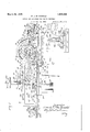
'a side elevation, partly broken away, show ing Aa rubber-shoe-uppering machine constructed according to my invention and adaptedv to carry'out the method involved therein.
Fig. 2 is a plan view machine with an upper, partly broken away,
laid thereon in position for-lasting.
'Fig 3l is a reverse plan view of parts shown in Fig. 2.
- Fig. 1 is a section on the line 4--4 of Fig..2. Fig. 5 is a perspective View of a link and lever forming a part of theactuatingimechi anism fora flexible toefstock-anchoringmem# ber or toe stretcher.
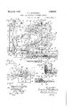
Fig. 6 is a -front elevation of one of the heel-Stock-anchoring members or heelstretchers, together with the trimmer-plate attached thereto. i
. Fig. 7 is a sideelevation illustrating the positions ofthe parts as the upper is being applied tothe last. w
Fig. 8 is a similar view illustrating the positions of said parts when the upper been stretched about the lat.
-strumentalities for` holding and manipulat! upon the.' underlying shoe parts, my inven` Of the accompanying drawings, Fig. 1 is.
of one end of the Fig. 9 is a partial plan view with. the
parts positioned as in Fig. 7 and' illustrat-V ingin brokenlines further positions Aof one of the .heel-stretchers.-
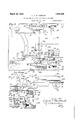
Figi 10 isa plan view of part ofthe operating mechanism, including devices for tripping the slide carrying the cam Whichrcontracts the toe-stretcher. F ig.' 11 is a section on the line 1111 of Fig. 10. Fig. l2 is aplan view gaged position the clutch which is disengaged in Fig.- 10.` Y
Fig. 13 is a Section' on the line 1313 'of Fig; 10.
showing in its en- Fig. 14 is a side elevation showing the y last and its support, together with the trimf` nung knife, its heater and actuating mechanism.
Fig. 15 ,is-fa view of partis shown in Fig. I
14,' together with oneofthe heel-stretchers and thevknife in trimming position.
Fig. 16 is a horizontal section on the line 116-16 ofFig 15, showing the stretching of one of the rear ends or wings ofthe upper around the heel part of the last, together with the knife in position to trim said end.
\ Fig.v 17 is a similar View showing the stretching` of the other rear end andthe co-operative relation of the trimming-plate and knife. Q l
. Fig. 18 is a Sectionon the line 18-18 of Fig. 14, illustrating an automatic one-Way friction-brake for the knife slide.
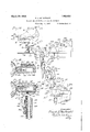
Fig. 19 (Sheet 1), is a side elevationshowing the rear end of the uppered last, tovgether with the seam roller and its actuat# ing mechanism.
General descaz'ptz'oa.
In' the embodiment of my invention here shown, the lastv comes to the machine with the rubberized cloth lining and other inner parts of the shoe applied thereto, and,'the
last-being supported, right side up, upon a pedestal, the machine applies over these lasted. parts a fiat, vulcanizabla sheet rubber upper or 'vamp of the usual form, joins its wings or heel portions in' a seam at the heel, and presses its toe marmn around theedge of the sole. y
The instrumentalities for so manipulating the vamp comprise a flexible U-'shaped toestock-anclioring member or toe-stretcher adapted to receive and adhesively` hold the loe-margin ot' the fiat vamp as the' latter is laid `thereon in an inverted, horizontal position. with its loe portion adjacent the toe ofthe last, a pair of heel-stock-anchoring members or heel-stretchers adapted concurrently so to receive and hold the heel margins'ot' the wing portions of the vamp, means for so moving the toe-stretcher; and heel-stretchers as to turn andv move the vamp over onto the last, lthe vamp .turning over its toe-portion, roughly, as a Center, means for turning the heel-stretchcrs 'Froinfa horizontal lo a. vertical plane to carry the wings oli the vamp into parallel relation with the sides ot the lasts vheel portion, and means for successively moving said heelstretchers to swing said wing portions around the heel ot the last, and apply them thereto, said stretchers contacting only the outer face of the vamp. Instrumentalities are also provided for closing the legs of the flexible' U-shaped toe-anchoring member to turn the margin of the vamp under the-edges of the sole and press it thereto,and members are provided for concurrently pullingthe vamp into the instep curves of the last. lA vertically moving, medially positioned knife, and actuating means therefor, are
provided for severing the excess stock from the Wings of the vamp as they are successively applied to the heel portion of the last, and
a seamroller, following the course of the' knife, is provided for rolling the vertical seam at the heel` ol the shoe after the knife has operated upon said Wing-portions vsuccessively. Last support.
'Referring first to Figs. 1l and 14, the machine here illustrated comprises a table 20, on the central part of which is mounted a pedestal 21, having 'at its top a shoe-last support 22ineluding a toe-rest block 23 and a lheel-rest block 24, the latter being carried on a slide so that it can be adjusted Jfrom and` toward the toe-^rest block to suit the length.
of different sized lasts, and the heel-rest block is provided With a pair of side gauges, onel being shown at 25, for lpositioning a shoe-last Q6 thereon. Said gauges, in any suitable manner, may 'be made adjust-able to accommodate shoe-lasts of different widths.
For holding the last 26 upon the-sup `ort 22, ai soft-rubber pad 27. adapted lto ear t upon the top of the last, is attached to the overhanging end of 'a clamping 'ariii 28 mounted to swing horizontally and slide verl tic-ally upon a post 29 rising from the table 20, said arm being urged upward on said post by a helical compression spring 30 and t adapted to be held down in clamping vposition, against the action .otsaid' spring, by a hand-.Wheel-nut 31 having seglnental threads (not shown) adapted. to engage a Toe stretcher. The vamp is shown, partly broken away,
at 34 in Fig. 2. The flexible U-sh'aped memi ber bfor anchoring the toe-margin of the vamp and swinging it over onto the last 1s designated-35 (Figs. 2, 3 and 4), its crosssectional form being clearly shown in Fig.
4. It is preferably of soft rubber, -whieh may be coated with rubber cement from time to time to assurethat the stock will adhere thereto, and in its opened out condition -tits within a bay eut in a. tiltable' and movable lplate 36, beingAsupported'therein by a curved series of small ' rectangular plates 37, 37 secured at their innerrends to the stocklanchoring member' and diverging outwardly therefrom, said plates slidably bearing upon the tiltable plate 36 and being connected with each other at their inner ends by links 38, 38, and at their outer ends by lost motion links 38, 38,- ,f
Instap pullers.
The tiltable plate 36 also carries a. pair `of instep- pull1ng pads 43, 43, adjustably' secured,- asv shown clearly in Figs. 2 vand 3,
49, -said slide-bars being mounted in apertures of the cr'ossshead shoe or guide-plate 491 and adapted freely to `slide therein as the heel-stretcher isturned between horizontal and vertical position about the moving pivot' The head 49t is adaptedvto abut the face of the guide-plate 49q to4 limit the movement the heel-stretcher toward the vertical position,I and the heelstretcher is provided with astop 49V adapted to abut the' v top of said guide plate to limit said heelstretcliers movement toward the horizontal position.
. For yieldingly holding the heel-stretcher 49 in either its horizontal or vertical position, while permitting it to be turned from the foriiier to the latter byits momentum or gravity when the mechanism is inverted, to
4twist' the wings of the vamp into vertical planes', and to be turned b ack by hand, itis connected by a pull spring` 49W `with the guide plate 49f1, 'said `spring acting overcenter with regard to the pivot 49m.
As shown in Fig. 6theheelestretcher 49is provided with a face-plate 49x which projvides its sliding surface .against the heel- Q stretchersuj'nporting plate 49d, and said face plate 49x is formed with an overhanging or half-'dove-'tail edge/19y adapted to interlock with a complementary doveftail flange -49Z on the plate 49d to prevent excessive strain on the pivot pin 495, said dove-tail edges or Cil flanges being curved substantially. concentrically with thepivot 49e (this feature not being shown, butvreadily understood by ref erence to Fig. 6), so that the heel-stretcher may turn about said pivot in adjusting itself to the last while sai-d dove-tail flanges continue in'en-gagement. Suitable stops shown, at 48, 48 (Fig. 9), as to the stretcher 48,
parts, so faras shown, are given the numeral 48 with the same enponent given with the numeral 49 in referring to the heel-stretcher 4a.
'ceZ-stretoh-eii frame. The heel- stretehers 48, 49 are supported,
by their rcspectire rack-bars 48T, 49" andv slide bars 48, 49, from a skeleton, heelstretcher frame pivoted concentrically with the 'pivot of the plate 36, said frame comL prising two parallel pairs of slide-guiding, radius bars 50, 50, 51, 51, (see especially Fig. 2) connected at their outer ends by a cross-member 52 of angle iron, and corner blocks 52, 52a, land said cross-.member 52A v,ieafiee vserves as a handle in turning 'the licel stretcher. frame and the pivotedtoe-stocle supporting plate 86 over from the stocleA coinpressionspring 55 on the bar 50 or 51` and an opposed, adjustable `pull spring 56 (Figs. 1, 7, 8 and 9) connecting theslide with apart of the pivoted frame adjacent said-cross-bar.
. The rack bars 482 49r and slide-bars 48, of the heel-.stretchers are slidably mounted, at right-angles to the'slide-guidingframe- bars 50, 50, 51, 51, in suitable guide apertures in the respective slides 53,
A54, th'ejteeth of each of the rack-bars 48T, 49"4 being inc shed with a pinion, 57, 58, mounted in a recess in the slide and splined upon a shaft, 59, 60, said shafts being rotatably and slidably mounted inV the. respective slides parallel with the'radiusbars of the'frame and adapted tobe turned successively, by means hereinafterl described, after their frame has been Jturned' overv onto the 15st first to run the heel-'stretcher 48 transverse .ly of th'e'macliine, inward to its medial, lstock-applying position, then slightly. past forward against the last when it is so run in to its medial position, the heel-sti-etcher'having at this stage fallen into .the vertical position as shown, with regard to heel-stretcher- 48, in FigsY, 8 and 9, and with regard to the heel-stretcher 49, upside down', in' Fig. 6,.
ilu
each ofthe slides 58, 54 hasadjustably secured thereto a pull-bar or silde bar, the one for the slide 53 being shown at 60, parallel 'withthe radius bars of thepivoted frame, `the o ppositeend lportion of said slide bar being slidably mounted in a bracket 61 secured to the adjacent pair of radius bars, and said slide bar is provided with a laterally projecting cam roller 62 running' in the 'elbow of a cam-arm 63,Y the latter being pivoted upon a bracketl 64 secured to the adjacent rafdiirs bars and provided with a hinge spring A65 to hold itinassociation with the roller 62 as the pivoted frameis turned to the stock-receiving 'position-of'Fig. 1. .The outer end of t-he cam-arm 68, with the pivoted frame as positioned in- Figs. 7 and 8, is adapted to be engaged 4by a cam or 'dog 5311,hereinafter described, topull the slide 53 along the radius bars 50, 50, against the action ofthe pull spring 56, the 'reaction of said pull spring returning'said slide, against the vcompression spring 55 When the eamor dog 53b1 has passed from under the cam arm v63. 66`is the nearer of a pair of stoplposts for the pivoted frame above described, each of said posts havingea hollow upper en'd adapted lto receive a rounded stud 6l formed on the bracket 61 or its fellow at the other side of the machine. the nearer of which is shown at 66l (Figl) y y are mounted upon" the table 20 and adapted 'lao 4to crowd the respective slides 53, 54, against the springs v55, as the heel-stretcher frame reaches loading position (Figs. 1 and 2), to assure the accurate positioning of the heelstretchers to receive the vamp.
Ach/,ating mechanism.
As above' stated, the pivoted frame ,carrying the heel-stretchers and the tiltable plate 36 carrying the toe-stock anchoring member are concentrically pivoted and they are adapted to move bodily as Well as to turn over their pivot, near the toe of the stock, from their stockreceiving position of Figs.
-1 and 2 to theirstocloapplying position of Figs. 7, 8. and 9. When said frame is stopped in its pivotal movement by the posts 66,' at which time the heelstretchers by reason of their-.momentum and weight snap into vertical position, overcoming their overcenter springs 48W,`49W, and thus hold the wings of the upper alongside and parallel to the heel of the last, the plate 36 requires to be further turned downward, from its position in Fig. 7 to its position in Fig. 8` to carry the toe margin down to the sole ot` the last. l
The plate 36 is provided atits respective sides with parallel arms 67, 67 (Fig. 2), ap-
proximately in its own plane, said arms being aperturedand mounted upon respective stub shafts-68, 69. rlhe arm 67 is secured against rotation upon its stub-shaft 68 by a pin 67", while the arm 67a is rotatably mounted upon its stub-shaft 69.` Said arms extend beyond said shafts, their outer ends being provided with transverse, springbacked plungers or latching pins 70, 70. Said stub shafts are rotatably mounted in respective bearing" brackets 7l, 71 rising from a carriage 72 extending across the-table 2O under the parts heretofore described and.
supported on said table at the far side, as viewed in Figs. 2 and l0, by rollers 73, 73 running on suitable. track-ways and at the near side by a rail 74 upon which the carriage slides. Adjustable stops 75 (Figs. 2, 7 and 10) and 76 (Figs. l and 10) `are mounted upon the table 20 to limit the movef ment ofsaid carriage, and ac pull spring 7 2a connecting it with a part ot' the table is adapted to urge it toward the last pedestal Cam members,
21, whichv is to say toward stock-applying.
position.
Each pair of the parallel radius bars 50,. 50, 51, 51a of the pivoted frame is provided with a bearing member 77 (Fig. 8) clamped upon the inner ends of the bars, said bearing dimple adapted to receive the adjacent one of the springspressed latching pins' 70 Vto hold the plate 36 and the heel-stretcher frame' substantially parallel as they are swung over from the position of Figs. l' and 2 to that of Fig. 7, but by the forcible dislodging of said latching pin from said dimple to permit the further turning of said plate to its position in Fig. 8, against an adjustable stop 36a, after said frame ,has been stopped by the posts 66, and likewise to hold them substantially parallel in the corresponding part of the reversemovement.
For `assisting the movement of the carsus5 riage 72 and so assisting the over-swinging y' pivotal movement of said plate and frame effected by means of the handle bai-520iV the latter, and for the further turning of .the plate 36, as well as to actuate certain cam-carrying frames hereinafter described, the stub-shaft 69, which it will be observed is looselyyjournaled in the members heretofore mentioned, has secured on its outer end a hand wheel 78 and a gear 79, the latter meshing with a two-faced rack bar 80, having teeth 8Oa on its top face and teeth 8Ob on its bottom face, said rack bar being the base or lower, horizontal member of a generally rectangular, vertically positioned, skeleton, cam-carrying frame 81, through the central open space of which the stub-shaft 69 eX- tends, said rack being slidably mounted, forv longitudinal movement on the table 20, between Vgrooved guide- rails 82, 82 secured upon said table. 68, has adjustably secured on its outer end a gear 83, of less diameter than the gear 79, the slots and screws for its angularadjustment being shown respectively at 83a, 83b (Fig. 1). Said gear is meslied with a rel-a- .tively short rack 84 adjustably secured by bolts 84a, 84 (Fig. l) uponthe lower,hori zontal member 85 of a generally rectangular, vertically positioned, skeleton, Camrarrying Jframe 86, through the central open space of which the stub-shaft 68 extends. Said lower horizontal, cam-carrying-frame Amember or rack bar 85 is slidably mounted for longi- The opposite stub-shaft,
pending from the table 20, under the rack members 80 and 85, is a transverse shaft 89 having secured on its respective ends gears 90, 90 of equal size, meshed respectively with the bottom rack teeth 8G", 85b of the rack members, 80, 85, and thus adapted tocompel the parallel cam-carrying frames 81, 86 to move equally, the trame 81 being driven by the gear 79. 1
Rotatably mounted upon the stub- shafts 68 and 69 respectively,'just outside of the respective brackets 71 of the carriage 72,
are plates, that for the'stub-shaft 6 9 being shown at 91 (Fig. 2), to which plates are adjustably secured, by means of screw bolts 91, 91a (Fig. 2, 7 and 8),'respectivevsegmental, bevel gears, one of the latter being shown/ at 92, said segmental gears being.
provided with respective radial cam arms 93, 94 each provided with a laterally projecting cam roller, 93u, 94, on its outer end, said rollers being adapted to be engaged by respective cams presently to be described for turning said segmental gears. The shafts 59, 60, above described as being" adapted, through the pinions 57, 58 respectively splin'ed thereon, to run the lieel-stretcherstransversely of the machine, rotatably extend through the respective brackets 61A above described and also through respective brackets 95, 95 slidably mounted on the adjacent radius bars 50, 50 or 51, 511 of the heel-stretcher trame, near the segmental gears 92, and Veach of said shafts has secured on its inner end a beveled pinion 96 meshed with the adjacent segmental gear, the latter beingthus adapted, when turnedby its cam, above referred to and hereinafter described, to drive the shaft 59 or 60, and thereby run the heel- stretcher 48f or 49 toward the middle of the machine. 7der returning the heelstretcher to the side of its frame, when the cam roller 93n or 94=L is freed from its cam, so that the heel-stretcher will clear the last as the frame is swung back to loading position, and will be positioned to receive the next flat upper, a helical torsional spring 97 is mounted upon each of the rsha- tts 59, 60, and has its respective ends anchored in a collar 98 secured upon the'shaft in abutment With the slidable bracket 95, and in a knurled Washer 99 slidably and rotatably mounted upon said shaft and provided with' adowel 'frame,' the beveled pinion 96 may b e unineshed with its segmental gear by sliding 1 said bracket and the shaft outward against the thrust of the spring 97and then allowed to return into mesh with the said gear undei' action of said spring at a diierent point on the gear, the latter meanwhile being given-.
a partial turn, to adjust the position of the corresponding heel-stretcher with relation to the cam-arm, 93 or 94, of the gear.
The arrangement so far described is such that, with the tiltable plate 36 and the heelstretcher frame and related parts in loading position, as shown in Figs. 1 and 2, the overswinging of the handle bar 52, which may be indirectly assisted as stated by turning the.
hand-wheel 78 counter-clockwise as viewed in Fig. 1 ermits the pull-spring 72 (Fim 10) to piiliJ h n last- 26 until it abuts' the stop 75 (Figs. 2 and 10)the gear 83 turning with the plate 36 and running on the rack 84, which is thecarriage 7.2 toward the shoev stationary until the over-swung traine is stopped b y the posts 66, while the larger gear'79, its -stub-shatbeing loosely jourand the bearing naled in the plate-arm167a lil() member arms 77 andy-77", runs an equal distance but at less angularspeed, upon the upper teeth-of the now stationary' rack-bar 80,;the `cam-carrying frames of which these* rack members'` are partsbeing at their lettliand limit as viewed iii Figs. 1, 7 and 8.
suitable stops (net shoivn),lbeing provided l toliinit theirk range of movement iii each di rection.- The heel-stretcher frame-fand the plate 36 thus travel bodily toward the last while being swung over their pivots.
l/Vhen theheel-stretcher -franie is stopped by the posts 66 further-turning of the handwheel 78 runs the cam-,carrying frames 81. 86 to the right as viewed in Figs; 1, 7 and 8, and in the beginning of this movement the` latter part ot' the rack 84, driving the gear l83, turns the Fig. 7 to that of Fig. 8, said rack then leaving said gear. A camplate 100 mounted in the cam-carrying traine 86 is adaptedto run with its edge in contact with an adjustable stud 101 (Figs. 1 and 7) projecting from the inner face of the gear 83, the adjustment slots and nuts 'of said stud being shown at 101, 101", to hold said gear in proper angular position to again mesh with the rack 84 upon the subsequent return of the latter.
iii
lli
plate' 36 from the position of 'l An adjustable rest 36a serves as a support tor the free end of the plate 36 when'it is in Y the position Shown in Fig. 8.
Heelstretchendcuatag vonnis.
in said plate, said cam being adapted to engage the cam roller 93 on the arm 93, as the frame 8G nieves forward as described,' (Figs. 7 and 8) to run the heel-stretcher 1S i1 ward to. its Amedial position, indicated vin d tted lines at S6e (FiO. 9), and hold it there while the trimming knife operates, and then, through the action o'ta terminal rise 86f on said cam, to run said stretcher beyond said medial position, to the dotted position shown at 86e' in. Fig. 9, to disengage thesevered margin of stock, after the triniming knife has operated, the reaction of thetorsional y spring 9T.then retracting the heel-stretcher when the roller 9S has passed trom said cam 86a. The cam 86a, being pivoted as described. passes over the roller 93il inoperatively during the return movement, leftward as viewed in Figs. 1, 7 andfS, ot the eamcarrying frame 86, said return movement being etliected by turning the hand wheel;
`clock-wise as here viewed betore theheel- ,strotcher ramefand platepfeare swung backsto loading positionthe reaction ofthe torsionalv spring 97 having thrown the canam 03 to its lowermost position in retracting the heel-stretcher 48. A generally similar eam 81, onthe frame 81 (Figs. 7 and 8) is pro vided :tor operating the heel-stretcher49 in like manner but after the heel-stretcher 18- has been run in and retracted. For pulling the slide inward on the rods 50, 50, when i the heel-stretcher48 has been run in to its nledial position. to present raid heels'tretcher to the last trom the rear, the frame S6 'carries a cam 53 adapted to actuate the. adjacent cam arm 63. In the subsequent return movement of the trame 86, the hinge spring '65 ot the cam arm 63 permits the latter to be swung away from its roller 62 by the canrct as the latter passes. it inoperatively, but returns the arm against the roller when the cam has so passed. A similar, later timed cam 54a, is provided on the trame 81 for .similarly presenting the heel- .stretcher 49 to the last from the rear when it has been run to its medial position by the cam 81a. The frames 81,' 86 also Carry respective cams, 81X (Fig. 2), and 86X (Figs. 1 and 7), adapted to engage the respective Vcam rollers 93, 94a, as the gears 7 9, 83 subsequently run on their racks vback to loading position when the heel-.stretcher trame is swung over, said cams, acting against the springs 97, being adapted to assure the accurate positioning of the heel-stretchers laterally of the machine to receive the next upper or vamp. Said cams may also be so termed and the springs 97 may be so tensloned that the latter will cause the heel-stretchers to separate vslightly to clear the last as their traine is swung over to stock-applying posi-r tion, the springs so movingthe heel-stretchdrs when the turning otthe trame swings the rollers 9 94 from said cams.
'F or actuating vthe angle levers 42 on the reverse side of the' tiltabl'e plate 36 and thereby closing the toe pressing pad 35. and
the instep pressing pads 43 upon the last, said levers areconnectcd by links 102, 102
with respective levers. 103. 101 extending through slots in the plate 30 i'rom a rockshaft 105 mounted in brackets 106, 106 on the opposite, work-receiving side. of said plate, and one of said levers. 104, is o'rnled with a cam arm' 101a (Figs. 2 and 5) having a laterally l'n'bjecting cam roller 104 0n said work-receiving side ot the plate. i Mounted between longitudinal. grooved, guide rails 107,107 on the carriage 72 is a'rack 10S; (FigsglO, 11 and 12) toothed on its bottom face and having rsecured on its back a vertical plate cam 109 adapted to engage the roller 104h ot the cam arm 10st?. the tiltable plate 36 being in stock applying position, to turn-fthe roclsh'a'lit 10b.V Said'rack 108'is .provided with a stop 108avadapted to abut a stop 1O8Jon one of its rails 10T to limit its movement toward its resting position, at the right in Fig. 10, and is adapted to'be urged toward said position by a weight 10.9a suspended by a windlass chain 110 secured to the hub of' a gear 11-1 loosely journaledon the' transverse shaft 89. abutting a stop collar 111i*- secured on said shaft. said gear being meshedwith. said rack. For driving said gear against the torce of said weight. to run the rack 108 to the lett as viewed in Fig. 10 and thereby carry the plate cam past the roller 1041*), the opposite side ot said gefans hub is formed with ratchet teeth, thus constitutingfa clutch member 112 adapted to be engaged by a complementary clutch member 118 grooved to accommodate a shipper fork 114a formed on a two-armed tappet lever 1141, said clutchv member 113 being spliued upon the shalt 89 and normally held ontot engagement. against a stop-collar 115 secured on said shatt.'by a helicalcompression spring` 116 mounted on said shaft and havingl its ends rotatably seated in axial-recesses in saidfelutch members. The tappet lever 11/1 is pivoted on a vertical axis 1141) on the under side 'of the table 2O and its tappet arm l is provided with an adyustable taopet-bolt 114C. A horizontal sleeve 11T under the table 20. is lformed with a .vertical gourrnal stem llaextending upward through a slot 118 in Vsaid table and the-stem is rotatably llU f adapted to abut the lever119 and through mounted in. an aperture formed ina cross member of the carriage 72.
'with a stop-collar 122a and adapted to be urged in the direction of said tappet Abolt by a pull yspring 123 connecting its downwardly bent rea-r end with said sleeve, said I. plunger thusl being adapted yieldingly to abut thc tappet bolt 114C to throw in the clutch113, 112 and thereby actuate the rack 108 to close in the toe-presser 35 and instep pullers 43 when the carriage 72 has reached the limit of its movement, towardvthe last,
releasing the clutch 113, 112 and thus pen' mitting the weight 109fL to return the rack 108 to its resting position at the right of Fig. 10 after it has functioned as just described, said rack has a dog 119 adjustably secured thereon by screws 1191), 119b and the latter to swing theA sleeve 117 out of alignment with the tappet bolt 114C, after the cam 109 has functioned, `the lever 104v and cam 109 then being in the dotted positions of Fig. 11, to slide the plunger 122 oli1 said tappet bolt, as indicated in dotted lines in Fig. `12, thus permitting the spring 116 to throw out the clutch and the weight 109 to retract th'e rack, the sleeve 117, vinder action of the spring 121, returning with its plunger into alignment with the tappet bolt, for the n'eXt operation, when the dog 119a is withdrawn by the retraction of the rack.
Stock-trimming cm'fe.
` I The knife 33 heretofore referred to, Vfor 'trimming the excess stock from the wings or heel portions of the upper as they are successively applied to the last, is shown' in Figs. 14 to 17. It is secured on the outer end of the upper arm 124a of a bell crank lever 124, the latter being fulcrumed at 1241 between fork arms formed on the upper end -of a vertically slidable bar 125 mounted in a guide-way formed in a bracket 126 depending from the table 20 and provided with a retaining plate 127. The lower arm 124C of the bell-crank lever 124 has ,its outer end connected by a link 128 with an arm, 129, se-
cured upon a rock-shaft 129a journaled inl 'the cam 133 or 135,
brackets, onev of which isshown at 130, mounted upon the table 20.y Another arm, 129", projects laterally from the other end of said rock-shaft and is provided with a laterally projecting cam roller 131 adapted to be engaged by successive pairs of cams 132, 133 and 134, 135 (Figs. land 14), on the cani-carrying frame 81, during the forward movement of the latter,'to the right as viewed in Fig. 1, to actuate the knife as the heel-stretchers in succession apply the wings of the upper to the last, the knife-supporting arm 124g, being, in each cutting operation, ,first thrown to vertical position and then raised with the bar 125 by the cam 132 012134, and then swung against the work and'drawn downward'bythe cam 133 or 135.
The vertically slidable bar 125 is provided at its upperend with adjustable stop bolts 136, 137, adapted to limit the angular movement ofthe bell-crank lever 124 at the positions shown respectively in full lines and in dotted lines in Fig. 14, and the lower arm 124c of said lever is connected by a pull spring 138 with4 the lower .end of the bar 125, to hold the lever 124 against the stop 137 when the cam'roller A131 is free from its cam. Said spring also assists the arm 1 29 in holding the knife 33 against the lwork as said knife is drawn downward, in its cutting movement, Withits supporting bar 125, by The vertically slidable har 125 is provided with alone way brake, 139, the details of which are shown in Fig.
18, adapted to resist' its downward move-l ment so as to assure that the downward pull of the arm 129 upon the bell-crank arm 124c will hold the knife firml against the work while pulling said `knife downward with the slidable bar 125 upon which it is mounted. Said brake comprises a friction member 140 adapted to bear against the bar 125, said member being mounted upon a backing member 141 mounted in a slot 142 in the bars retaining plate 127, and said backing member being formed on its outer face with a recess containing a metal ball 143 bearing against an inclined plate 144 secured to the retaining plate 127, this arrangement being such that the downward force exerted by the bar 125 upon the friction member 140 wedges the latter with its backing member 141 and its ball 143 between the bar 125 and the inclined plate 144, thereby increasing the pressure and braking effect of the member- 140 upon said bar. 1t will be seen that the upward movement of the bar 125, on the contrary, in upwardly displacing, these wedging members, reduces and substantially nullities their braking edect. A compression spring 145 is interposed between the backing member 141 and a bracket 146 thereover, said bracket being secured to the retaining plate 127 for lightly holding the Wedging members in braking position so as" sol vdrag of the bar 125.
I meente Knife heater. *Toy facilitate theV cuttingfo the knife 33 a burner1471fis knife, asshown in Fig. 14, whensai'd knife is in the full line position there shown,
.which it assumes between cutting operations.
A cover 148, slottedto receive the knife arm 124, is provided. for said burner.
Seam-rolling device.
The seam rolling device, shown in Figs. 1 and 19, comprises a rough-treaded roller 149 mounted on the end of one arm, 150,
of al bell crank lever 150,-the latter being fulcrumed at 150b on a slide 151 mounted for vertical movement upon the p'ost 29 and constantly' urged upward by a weight 152 connected with said slide by a chain 153 running over a` pulley 154 loosely journaled on said post. bell crank .lever is connected by a link 155 with an arm 156 projecting from the inner end of a transverse rock-shaft 157, the latter being mounted in suitable brackets, one being shown at 157, upon the table20, the outer end of said rock-shaft being provided with a camp-actuated arm 158 provided with a laterallyprojecting cam roller 159 adapt--- ed to be engaged by a cam 160 pivoted upon a bracket 161 carried by an extension of the cam-carrying frame 86,y during the leftward or return movement of the latter, to throw the roller 149 againstl the work and draw it' downward along the heel seam, the slide 151 being drawn downward, lifting the weight 152, as the downward pull of the link 155 continuesafter the roller has been swun into contact with the work. The rock-sha t 157 is provided with a suitable torsion spring 157", mounted thereon and having its ends anchored in said rock-shaft and in one of its brackets respectively, tocause the arm 156 to rise as soon as the roller 159 passes from its cam, to clear the work as the slide 151 is returned upward by the weight 152.
Mownt/ag of pz'cotedv cams.' The cam l160, in `order that it may pass over the roller 159 inoperatively during the first, forward movementof the cam-carryin O frame 86, and in order that its position and pitch may readily be adjusted, is -pivoted upon a stud' (not shown) eccentrically positioned upon the innerside of a ld1se 162 rotatably mounted in the? bracket 161, the outer side of said disc being provided with a lever 163 -having a'slotted' outer end'in which'is mounted a clamping bolt 164 pro# i lposition'ed' on the table 20 that its rviiane'fwill heat said'.
The other arm, 150", of the' at corresponding positions. (The cams 132 and 134 are similarly pivoted, sothat they may pass inoperatively over the cam roller 131 of the cuttinggdevice during the return `movement of their frame 81, their pivot "studs being shown respectively at 1322 134a (Fig. 1), their discs at 132,", 134", and the clamping lever for the cam 132 being shown in Fig. 14 at 132. The vertical plates upon which thesecams are mounted are formed with several arcuately arranged clam ingbolt holes to increase the range of a justment afforded by the slots in the ends of their levers, such holeswith respect to the Cam 132, being shown at 132, 132d in Fig. 14, and the clamping bolt, 132e, being adapted to be` mounted in any of said holes.
Last gauge. For facilitating the exact positioning of the shoe last 26 with respect to the vampapplying mechanism, a forked gauge member 165 is hinged upon a bracket 166 secured to the edge of the plate 36 which is adjacent the last when said plate is in loading position, as shown clearly in Fig. 2, the forks of said gauge member being adapted to receive ythe toe of the last between them as there shown. v Said g..uge member 1s pr0- vided with a hinge spring 167 to permit it yieldingly to contact the sole of the last, without raising the latter, when it is brought up to the toe of the last by the turning of the plate 36 back to loading position.
An angle iron 168 secured to the table 20 (Fig. 1) is adapted to serve as a stop or lrest for the handle-bar 52 of the heel-stretcher frame when the latter is in loading position.
Operation.
In the operation'of the machine, the parts .being in the position shown in Figs. 1 and 2, the upper or vamp, 34. with its last-contacting side uppermost, is laid upon the supporting block 34", about the gauge 34C, as shown best in Fig; 2, and its margins adhesively anchored to the toe-stretcher 35, and the heel- stretchers 48, 49, the knife backing plate 49h being swung on the pivot 49j to admit the stock and then permitted to close upon the latter under action of its spring 49k. The shoe last, with the inner parts of a shoe thereon, is mounted upon the pedestal 21 and clamped thereon by means'of the arm 28. The camcarrying frames 81, 86 are at their leftward limit, as viewed inv Fig. 1, wherefore the weight of the heel-stretcher frame, the plate 36, and their associated parts, holds the car' riage 72 at its right-hand or outward position, against or adjacent the stop 76, against the pull of the spring 72a. -The heel-stretcher frame, together with the tiltable plate 36 and their associated parts, are then swung over toward the last by means of the handle l bar 52 to invert the vamp and present it from above to the last. During this overswinging movement the gears 79, 83 run respectively upon the now stationaryracks 80, 84, the vamp thus being moved bodily toward the last as well. as turning over, and the carriage 72, being pulled by the spring 72a, correspondingly moves toward the last until it abuts the stop 75. When the carriage is .thus stopped, or immediately thereafter, the turning movement of the heel-stretcher frame is suddenly'stopped by the posts 66, and the weight and momentum of the heelstretchers thereupon causes them lto snap into vertical position as above described."
Further turning of the hand-wheel 78 v in the samedirection, the carriage being stopped as stated, drives the cam-carrying frame 81,'thr0ugh the gear 79 and rack teeth 80, to the right as viewed'in. Fig.` 1,- and through the rack teeth 80", gears 90 o n the Shaft 89, and the rack teeth 85", drives the cam-carrying frame 86 in thev same direction and atthe same speed as the frame' 81. This forward movement of the frame 86, through the rack 84 thereon, drives the gear i 83 and thereby further turns the plate 36,
about its now stationary pivot, from its po- ,sit-ion in Fig. 7, to that in Fig. 8, to pull the cam 109 contacts the roller.104b and through parts abovel described closes the toe-stretcher 35 and, instep pullers 43 inward with respect to the last to pull the uppervstock respectively about-the edge-of the toe-portion or the last and into the instep curves of .the latter. This action' completed, the dog 119a strikes the arm 119, thus releasing the clutch 112, 113, through parts above described, and permits the weight 109 to return the rack 108 for the next operation.l
yAt aboutv the same time that. the toestretcher and instep pullers are thus, operatedv the forward movement of the frames 81, 86, to the' rightjas' viewed in Figs. 1,7 and 8, brings first the cam 86a into contact with the roller 93a on the arm 93, which latter has been thrown to its lower position by the4 over-swinging of the heel-stretcher frame, and said ycam, through parts above described, runs the heel-stretcher 48 inward to a medial position, and while it is so held by the Straight, middle portion of said cam, as shown-in Fig. 8, the cam 53a contacts the arm 63 to move the heel-stretcher 48 forward against the last, through parts. above described, 'and so hold it while the knife 33 is actuated and withdrawn by the cam 132, 133.
The terminal rise 86t of thefcam' 86a then shoves the heel-stretcher 48 v,slightly beyond its medialv position, substantially to the posi tion indicated by broken lines at--86g in Fig 9, to disengage the lsevered' margin of stock from the work. The pull spring 56 then retracts the heel-stretcher 48 rearwardly from the last and, the cam 86n leaving the roller 93, the spring 97 runs the-.'heel-stretcher back, laterally of the machine, to a 'position adjacent the frame bars 50,y 50a.
Similar operation of the heel-stretcher 49 is then effected by the cams 81a, 54, and corresponding parts, the knife 33 being now actuated by the cams 124,135, during the further outward movement of the frames 81, 86 When. the latter have reached the forward limit of their movement, the hand-wheel 78 is turned in the opposite direction, clockwise as viewed in Fig. 1, to return said frames to their leftward limit as there viewed, and during this return movement the cam 160 actuates the seam roller 149 through -mechanism above described. When the frames 81,` 86 have `reached their leftward limits as. viewed in Fig. 1, further clockwise turning of the hand-wheel 78, assisted by means of the handle 52,` runs the gears 79, 84 upon their respective racks, the carriage 72 moving against the pull ofthe spring 72a, and the heel-stretcher frame and the plate 36,
with the parts carried thereby, are thus swung back to loading position, the cam members 66EL augmenting the pull springs i to cause the proper positioning of hee stretcher slides. The last with the work thereon ,is then removed, and the operationA asdescribed is repeated.l
While the fore oing description relates to a last which is a hesively prepared by having the lining and theinsole mounted thereon as it comes to the machine, it will be apparent that the invent-ion -is, independent of the presence or absence of these inner shoe parts, and for the sake of brevity and clarity of expression the term lastr will be used .in the appended claims as applying to a last either with or without these inner shoe parts thereon. The word upper also is intended to include an upper shoe part such as a lining.
It is also to be understood that appliean has-used the word lasting inthe appended claims inits broader sense, as relating` to the application of' shoe parts to lasts, and not in the more restricted sense of securing the margin of the upper to the insole.
An especial advantage'of the heating of the knife is that it permits the knife to trim the first-applied heel margin, with the last and the shoe lining thereon serving as a backing plate forthe knife to. cut against, l
as shown in Fig. 16, without such sharpness holding it extended throughout itsarea by en of the knife or such force of the knife against 7. enga the lining or the last asl to cut or score the' same, the heat of the knife causing the rubber to soften so .as to cut easily and permit the passage of the knife without 'drawing' and wrinkling of the cut margins by frictional contact with 'the knife.
Various modifications may be resorted to without departingfrom the scope of my invention, and I do not wholly limit my claims to the embodiment thereof described herein.
I claim: 1. The method of lasting shoes which-comfrrement with its outer face only, twist .ing tlie wing portions ofthe upper into subprises pulling an upper shoe part by its margin onto the last by non-progressive, adhesive engagement with the outer surface only of said margin.
2. The method of lasting shoes which comprises holding an upper shoe partand a last in determinate, isolated positions, bringing.4
the last and said part together by determinate relative movement, and pulling said part onto the last by non-progressive, adhesive engagement with only the outer face of a marginal portion thereof.
3. The method of lasting shoes which comprises holding an upper shoe part and a last in determinate, isolated positions, bringing the last and said part together by determinate relative movement, and pulling' said part onto the last and drawing its margins inward past the sole of the last by non-progressive engagement withxits marginal por.
ltions only.
l4. The method of lasting rubber shoes which comprises applying a raw gum upper to the last, land pulling its respective heel portions around the heel partof. the last to apply them progressively thereto up to the positionof the vertical heel seam by engagement with the outer face only of the upper.
5. The method of lasting rubber shoes which comprises sticking 'the bottom and 'rear edges of a rawf gumlupper `by their outer surface/ to suitable toe and heelstantial parallelism with the sides of the heel portion of the last while so holding them' extended', drawing the toe margin of the upper, while it is so held, toward the sole-edge of ythe last to stretch the upper onto the lasted parts, and successively swinging the wing portions ofthe upper, while they are so held, about the heel of the last to apply them adhesively to the lasted parts thereon. v
8.' The method of applying a rubber upperV I to a last which comprises presentingy its forward portion to the forwardv portion ofthe last, swinging one of its heel portions about the heel of thelast by engagement with its outer face only and adhesively securing it on said heel of the last, severing the. excess stock from said heel portion of the upper,4
and then likewise swinging, securing and severing excess stock from the other heell portion of the upper.
9. The method of lasting rubber shoes' which comprises preparing a last with an adhesive coating and positioning it upon a support, positioning the lraw gum upper with relation to said last, and inverted, upon an adjacent support, swinging said upper over onto the last, by engagement with its margins while holding it substantially flat, stretching it against the last, progressively drawing it intocontact with the last toward' last support and adapted to receive an in verted upper in position to be swung over onto a last'on said last support, a gauge stretchers, and by such engagement drawing said edges respectively past the sole at the fore-part, and around the heel, of a last.
E 6. The method of lasting rubber shoes which comprises applying the lining and bot-tom edge-past the sole atftlie fore-part of the last. 1 i
` 7. The method of applying a rubber upper .to a la'st having-thereon the lasted underlying parts of shoe which comprises presenting saidup'per to. said lasted parts while for positioning said upper on its support, andan upper-transferring mechanismincluding a toe-stretcher and heel-stretchers constrained to move 1n determinate courses to sok swing said upper and apply it to the last in a position thereon determined by said gauge. I
11. A shoe lasting machine comprising a last support, an adjust-ablelast gauge there-y on, an upper-supporting member having a position fixed with relation to said last support and adapted to receive an inverted up# per in position to be swungover onto a last on said last support, an afdjustablegauge for positioning said upper on its support, and an upper-.transferring -mechanisin including a toestretcher and heel-stretchers constrained to Vmove indeterminate courses to so swing said upper and apply itto the last in apositionk thereon determined by said gauge,
lsaid upper-transferring mechanism being adjustable to vary the course of said toelast support, a flexible toe-stretcher positionable adjacent thereto and adapted to receive and adhesively hold the margin of an in- -verted upper, means for moving said toetretcher so as to swing said upper over onto the last, said means and said toestretcherbelng adapted to apply the upper -irst to the toe portion of the last and then draw it progressively and With substantially uniform tension into contact with the last, and means for changing the shape of said toe-stretcher to conform it substantially to an outline of the last.
13. A shoeelasting machine comprising means for holding an upper shoe part ina determinate position, means for supporting a last in a determinate position isolated from that of the said part,and means for so moving one of the aforesaid means with relation to the other as to bring said last and said part together in determinate.. relation, a part of the upper-holding means being adapted to pull the part ontothe last by adhesive engage ment Witlronly the outer face of a marginal portion thereof. y
14. A shoe-lasting machine comprising `means for supporting a. last with aU-shaped upper applied to the forward part thereof,
and members adapted to hold the respective; heel portions extended in substantially par-A Iallel relation to the sole of the last, said Sti members beingmounted for such movementv vas totwist said heel port-ions into substantial parallelism With the sides of the heel, portion of the last While holding them lsoextended, and to swing said heel portions successively about the heel of the last.
15. A shoe-lasting machine comprising means for holding a last, and means for pulling an upper shoe part by its margin about said last by non-progressive, adhesive engagement with theouter face only of said margin. 1
16. A shoe-lasting machine comprising means for bringing an upper shoe part and alast together in determinate relation from determinate, isolated positions, and `means for pulling said part by non-progressive engagement with its margin to stretch. it
ove; the last and draw said margin inward about the sole of the last.
17 A rubber-shoe uppering machine comprising means for bringing an adhesive, U-
shaped upper shoe-part and a last together" in determinate relation from determinate, isolated positions, and means engaging the outer face only of said part for swinging its heel margins around the heel the last.y y f 18. A shoe-lasting. -machine comprising means forV supporting a last, a U-shaped toertion of stretcher and a pair of heel-stretchers adapted to receive the upper in a substantially flat condition, the heel stretchers being .other to present said upper to the last, to
pull its toe margin past the sole of the last, and to swing its heel margins about the heel portion of the last.
19. A shoe-lasting machine comprising means for supporting a last, a U-shaped too lstretcher adapted to recelve an upper Shoe part in a substantially lat condition and hold its margin, by contact with the outer face only .of said part andmeans for effecting such relative movement between .said stretcher and said last as to present the upper to the last and stretch it thereover.
20. A` shoe-lasting machine comprising means for supportinga last, a- U-shaped toestretcher anda pair of heel-stretchers adapted to receive the upper in a substantially flat condition and hold its margins, by contact with the outer face Jonly of the upper, and means for effecting such relative movement betweens'aid stretchers and said last as to present the upper to the last and stretch it thereover.
21. A shoe-lasting. machine comprising means for supporting aflast, a U-shaped toeflat condition and hold its margins by contact with their outer face only of the upper, means for effecting suohrelative movement between the last and said .stretchers, as to present the upper to the last andpull it approximately into shoe formabout the last,
means for closing .the toe margin of the upper -about the sole-edge of the last, and means for swinging the heel margins suc eessively against the heel,of the last and joining them in a heel seam.
22. A shoe-lasting machine comprising a contractile structure adapted to anchor a piece of shoe stock solely by engagement with a marginal portion thereof, means for bringingsaid structure and a last together in determinate relation from isolated, determinate positions, and means for contractiU-shaped, lexible .member adapted to re- 'ceive 1n at condition and anchor Ithe maring said structure to close the margin of said piece vtoward the last.
upper toward a last associated therewith,
and a series yof spaced members secured to said U-shaped member and adapted to modify the exure of its legs to conform them to an outline of the last.
U-shaped, flexible member adapted by lad y sive contact therewith to anchor the margin of an upper shoe part, and means for flexing the legs of said U-shaped member toward each other to pull the upper-margin secured thereto against a last associated therewith. 26. A shoe-lasting machine comprising a contractile structure adapted to anchor an upper `shoe part by engagement with only 2o the outer face of the toe margin of said part, means for bringing said structure anda last together in determinate positions, and means for so ycontracting said structure as to pull said part over the last and .draw its margin inward about the sole of the last.
27. A shoe-lasting machine comprising a pair. of heel-stretchers adapted in one position to receive the heel portions of an upper. and to hold the same substantially in the same plane by engagement with one face only of ".said heel portions, means for so mov- `ting said heel-stretchers as to twist said heel portions in opposite directions into substantially parallel-relation with each other, and 35. means forthenmoving said heel-stretchers, each toward theother, to swing said heel portions about the heel of la last held adjacentthem.` .f l*
28. A shoe-lasting machine comprising a .-40 vpair of heel stretchers adaptedin one positionto receive the heel portions of a U- shaped upper shoe-part and to hold the same substantially in the same plane by engagement with their rear margins, means for so movingksaid'heel stretchers as to twist said heel portions in opposite directions into substantially parallel relation with each other, and means for then moving said heel stretchers, each toward the other, to swing said'heel portions about the heel of an adja- `cent last. f l 29'.- A shoe-lasting machine comprising means for holding a last and means for pulling a piece of rubber shoe stock about sai-d last,'the last-mentioned means comprising a member adapted to hold said stock by engagementwith one: faceonl ofthe latter, said member being formed with a slot adapted to be bridged y the pulled'stock in the pulling operation and to give access for the trimming of said stock.
30. A shoe-lasting machine comprising means forholdinga last, means for pulling a piece of rubber shoe stock about said last,
25. A shoe-lasting machine comprisingla hthe last-mentioned means comprising a member adapted to hold said. stock by engagement with one face only of the latter, said member having. a holding face adapted to anchor the' stock' and anon-adhesive surface adjacent thereto adapted to press the ystock against the last while permitting -access to the stock for trimming the latter adjacent said-holding face. y
31. A shoe-lasting machine comprising means'for holding al last, meansfor pulling ak piece` of rubber'shoe-stock about said last by non-progressive engagement with said piece to secure it adhesively thereon, means for severing excess stock from said piece adjacent said pulling means when it has been so secured, and means for actuating said pulling means and said severing means in determinate relation.
32. A shoe-lasting machine comprising means for holding a last, means for engaging the margin of a piece of rubber stock, means for so moving said engaging means as to pull said piece of stock about said last, means for cutting said stock, along said margin, when it has been Se pulled, and
means for further moving said stock-engaging means to disengage said margin from the work.
33. A shoe-lasting machine comprisinga pair of heel-stretchers adapted to receive and secure the heel portions of an upper Aapproximately in the same plane by engagement with their outer faces only, means for spreading said heel-stretchers apart to admit a llast between said"heel' portions, means for turning said heel-stretchers in opposite directions so as to bring said heel portions approximately into parallel relation with the sides of the lasts heel, and means for moving said heel-stretchers laterally of the lasty the upper A to swing said heel portions of about the heel of the last.
34. A shoe-lasting machine comprising means for holding a last, means for presenting the forward portion of the upper and the forward portion of the last to each other, means for swinging the heel portions of the upper about the heel portion of the last by engagement with one face only of the upper to join them in a heel seam, means for sever- .y
ing excess stock from said heel portions, and actuating means for the several aforementioned-stock manipulating means adaptedto4 actuate them in ldeterminate relation.
35. A shoe-lasting machine comprising means for holding a last, means for presenting the forward portion of the upper and the forward portion of the last to each other, means for swinging the heel portions, of the upper about the heel portion of the last by enga ement with one face only of the upper tojoin them in a heel seam, means for severing excess ,stock from said heel portions,
means for rolling the heel seam, and actuating means for the several aforementioned stock manipulating means adapted to actuate them in determinate relation.
36. A shoe-lasting machine comprising a pair of .heel-stretchers and a contractile toestretcher adapted to receive an upper and hold the same substantially in a flattened outcondition by engagement with one face only of its margins, a last, means for associating said lastv With the upper so that the latter is stretchedfrom said flattened out condition toward shoe form by contact with the last, means for contracting .said toe-stretcher to apply the toe margin of the upper to the last, means fori turning said heel-stretchers in o'p-- posite directions so as to bring the heel portions of the upper substantially parallel with the lasts lieel, means' for successively moving said heel-stretchers to a medial position at the rear of the last, forward against the last, then laterally beyond said medial position, and then backward and laterally, substantially to their former positions, means for trimming the stock vadjacent said heelstretchers as,they are successively presented to the last, and actuating means for the several aforementioned means adapted to actuate them in determinate relation.
37. In a shoe uppering machine, a heelstretcher and actuating means therefor com prising a pivoted frame, a transverse rack bar mounted on said frame, a stock anchoring member mounted on said rack bar, a pinion journaled on said frame and meshed with said rack bar, and means for driving said pinion to run and retract said stockanchoring member.
38@ In a shoe uppering machine, a heelstretcher and actuating means therefor comprising a pivoted frame, a slide mounted for radial movement thereon, a rack mounted for transverse movement on said slide, a stock-anchoring member mounted on said rack, a radial shaft mounted on said frame, a pinion splined on said shaft and meshed With said rack, means for turning said shaft, and means for movingsaid slide on said frame. v
39. In a\shoe uppering machine, a heelstretcher and actuating means therefor comprising a pivoted frame, a slide mounted for radial movement thereon, a rack mounted for transverse movementon said slide, a stock-anchoring member mounted on said -f rack, a radial. shaft mounted on said frame,
a pinion non-'rotatably `mounted on said shaft, meshed with said rack and adapted to drive the latter at dierent radial positions on said frame, and means for turning said shaft.
40. In a shoe uppering machine, a heel- I stretcher and actuating means therefor comprising a pivoted frame, a slide mounted for radial movement thereon', a rack mounted 65 for transverse movement on said slide, a stock-anchoring member mounted on said rack, a radial shaft mounted on said frame, a pinion non-rotatably mounted on said shaft, meshed With said rack and adapted to i drive the latter at different radial positions on said frame, a spring adapted to turn said shaft in one direction, and cam means acting against said spring to turn it in the opposite direction. y
4l. In a shoe uppering machine, a heelstretclier and actuating means therefor com prising an over-swinging frame, and a stockanclioring member pivotally and slidably mounted on said frame, its pivotal axis being substantially radial with respect to the over-sWinging axis of said frame, said stock anchoring member being adapted to be turned on its pivot by the over-swinging movement of said frame. Y
42. In a shoe uppering machine, a heelstretcher and actuating means therefor comprising an over-swinging frame, means for stopping said frame in its over-swinging movement, and a stock-anchoring member pivotally mounted on said frame and adapted'to be turned` upon its pivot by momentumor gravity upon the stopping of said frame by said stopping means.
43. In a shoe uppering machine, a heel-m5 stretcher and actuating means therefor comprising 4an over-swinging frame, a stockanclioring member slidably mounted thereon for movement in a radial and inl a transverse direction and pivoted on an axis substan- 10() tially radial With respect to said frame, and means for actuating said stoclranchoring member in its pivotal movement and in its sliding movements in determinate order and amplitude.
44. In a shoe uppering machine, a Vheelstretcher and actuating means therefor comprising an over-swinging frame, a stock-anchoring member slidably mounted thereon for movement in a radial and in a transverse direction and pivoted on an airis substantially radial with respect to said frame and also on an axis transverse thereto, stops and springs adapted to regulate its pivotal movements, and meansfor actuating said stock- 'with said rack, and a stock-anchoring inem- 125 bei' on said mounting.
46. In a shoe uppering machine, a heel-- stretcher and actuating means therefor coinprising a rack, a heel-stretcher mounting,l a link connecting said rack with said 'inount ing, a guide member lslidably associated with said rack and pivoted to saidmounting; anv
over-center spring connecting said mounting With said rack, a stock-anchoring member pivoted on said mounting on` an axis' sub.
stantia-lly parallel with said rack when said stock-anchoring member Ais in stock-applying position, means for stopping said stock-'anchoring member in movement about said axis, and a spring for yieldingly urging it toward said stop.
47. In a shoe uppering machine, a heelstretcher and actuating means therefor com prising an over-swingimgA frame, a slide"-` mounted for radial movement thereon, a
heelstretcher-supporting member mounted said slide, the last said means, comprising a' cam lever N,'actmg between said 'fi-aine and slide, a cam for actuating said\lev er, and a return spiing for said lever.
48.* A shoe uppering machine comprising a llast support, a contractile toe-stretcher, a pivoted mounting for the latter, a lheelstretcher framev pivoted substantially concentrically with said toe-stretcher mounting, a'. pair of heel-stretchers on said frame, said toe-stretcher andv lieel-sti'etchers ,being adapted to receiveand hold an upper in a subA stantially flat condition, and j said toestretcher mounting and heel-stretcher frame being adapted' to be turned together about their pivot to present an upper carried thereby to a last mounted on said last support, means for stopping said frame with the licel-stretchers at respective sides of the'heel of the last, means for further turning said toe-stretcher mounting to pull the upper toward the sole of the last, and means for contracting said toe-stretcher to piill'the mar gin of theupper against the last.
49. A shoe upperingniachine comprising a table, a last supportmounted thereon, a carriage movably supported on said table, a toe-stretcher mounting and abcd-stretcher mounting pivoted substantially concentrically on saidcarriage, said carriage being adapted to be moved, toward said last support, concurrently with the swinging of said toe-stretcher support and heel-stretclier support over their pivotstowardsaid last support, and atoe-stretclier and a heel-stretcher l mounted on their respective aforementionedsupports. i y
50. A shoe-.upperingmachine comprising a table, an over-swinging frame thereon, a stock-manipulating device on said overswinging frame, means for stopping said surface of thel last and to act against the frame in a determinate position in its oversvvinging movement, a cam cari-ying member slidably. mounted on sa'id table, and arcani lcarried by -said member andvadapted to ac- -tuate said stock-manipulating"device when said frame is inits stopped `position'.
` 51. A shoe-uppering machine comprising a table, avv last supportmounted tlieieoma rack slidably mounted on said table, a car-4 riage mounted for movement parallel with said rackon said table, a toe-stretcher support and a heelstretcher .support pivoted concentrically on said carriage,- a -toe stretcher device and a heel-stretcher device mounted on said supports respectively, said' carriage being movable toward said last-support concurrently With the ovei'-sw.ingiiig of said lieellstretcher support and toe-stretcher support toward said last support, means for stopping said heel-stretcher support in said over-swinging movement, a gear journaled on said lcarriage and meshed with 'said rack,
means forturningsaid gear to drivefsaid rack, a cam-carrying :trame carried by said rack, and cams on said frame adapted to aC- tuate said heel-stretcher device.
52. A shoe-lasting' machineA comprising means :for supporting a last, means adapted by engagement with a margin of a piece of stock to pull thestock onto the last, and a knife mounted to travel relatively along\the last as a cutting block to cut vthe stock.
53. A shoe-lasting machine comprising meansfor supporting a last, means for joining the margins of anv upper on the last in a seam, a seam-roller, and means for running the roller on the said seam.
54. A lshoeslastingmachine las defined in I claim 53 including a seamtrimming device and meansfor actu'atingthe said device and the seam roller in determinate'relation.
55. A rubber-shoe uppering machine comprising means for lsupporting a last with upper stock thereon, a knife adapted to cut said stock, means for actuating said knife land for returning it to a determinate position betWen operations, and aheater so positioned as to heat said knife when the latter is in said determinateposition.
, 56. A shoe-lasting machine vcomprising means for supporting a last with an upper thereon having a height-Wise heel seam,- a tool adapted to operate along said seam, meansA lfor* yieldingly holding `said tool `against, the Work, and means for, running said tool along said seam `Whilesaid tool is" so held. i
l57. A slice-lastingI machine as. defined in claim 56 in which lthe means for running the.
tool is adapted to exert up'on the tool a component of force directed toward the Work` A 58. A shoe-lasting machine as defined in claim 56 inwhich the toolfis adapted to be Y
Priority Applications (1)
| Application Number | Priority Date | Filing Date | Title |
|---|---|---|---|
| US582884A US1663456A (en) | 1922-08-19 | 1922-08-19 | Method and apparatus for making footwear |
Applications Claiming Priority (1)
| Application Number | Priority Date | Filing Date | Title |
|---|---|---|---|
| US582884A US1663456A (en) | 1922-08-19 | 1922-08-19 | Method and apparatus for making footwear |
Publications (1)
| Publication Number | Publication Date |
|---|---|
| US1663456A true US1663456A (en) | 1928-03-20 |
Family
ID=24330855
Family Applications (1)
| Application Number | Title | Priority Date | Filing Date |
|---|---|---|---|
| US582884A Expired - Lifetime US1663456A (en) | 1922-08-19 | 1922-08-19 | Method and apparatus for making footwear |
Country Status (1)
| Country | Link |
|---|---|
| US (1) | US1663456A (en) |
-
1922
- 1922-08-19 US US582884A patent/US1663456A/en not_active Expired - Lifetime
Similar Documents
| Publication | Publication Date | Title |
|---|---|---|
| US1663456A (en) | Method and apparatus for making footwear | |
| US3849818A (en) | Adhesive control for shoe lasting machine | |
| US1721736A (en) | Machine eob shaping uppers | |
| US3165771A (en) | Apparatus for lasting footwear | |
| US2096761A (en) | Machine for operating on stitchdown shoes | |
| US2333708A (en) | Assembling machine | |
| US1267370A (en) | Lasting-machine. | |
| US2050377A (en) | Machine for shaping uppers over lasts | |
| US1487915A (en) | Upper-shaping machine | |
| US2078330A (en) | Assembling machine | |
| US274207A (en) | Thirds to melville s | |
| US1897037A (en) | Machine for shaping shoe uppers | |
| US3011186A (en) | Toe lasting machine | |
| US938514A (en) | Lasting-machine. | |
| US1979000A (en) | Lasting footwear | |
| US2925613A (en) | Toe lasting machines | |
| US3594838A (en) | Lasting machines | |
| US780996A (en) | Lasting-machine. | |
| US1943344A (en) | Machine for use in the manufacture of shoes | |
| US2086526A (en) | Method of and means for use in manufacturing footwear | |
| US1261483A (en) | Toe-lasting machine. | |
| US1409190A (en) | Machine for shaping uppers to lasts | |
| US1030820A (en) | Lasting-machine. | |
| US1745451A (en) | Lasting machine | |
| US1965217A (en) | Air control for shoe press machines |