US1663441A - Box - Google Patents
Box Download PDFInfo
- Publication number
- US1663441A US1663441A US39358A US3935825A US1663441A US 1663441 A US1663441 A US 1663441A US 39358 A US39358 A US 39358A US 3935825 A US3935825 A US 3935825A US 1663441 A US1663441 A US 1663441A
- Authority
- US
- United States
- Prior art keywords
- box
- cleats
- cover
- portions
- meat
- Prior art date
- Legal status (The legal status is an assumption and is not a legal conclusion. Google has not performed a legal analysis and makes no representation as to the accuracy of the status listed.)
- Expired - Lifetime
Links
Images
Classifications
-
- B—PERFORMING OPERATIONS; TRANSPORTING
- B65—CONVEYING; PACKING; STORING; HANDLING THIN OR FILAMENTARY MATERIAL
- B65D—CONTAINERS FOR STORAGE OR TRANSPORT OF ARTICLES OR MATERIALS, e.g. BAGS, BARRELS, BOTTLES, BOXES, CANS, CARTONS, CRATES, DRUMS, JARS, TANKS, HOPPERS, FORWARDING CONTAINERS; ACCESSORIES, CLOSURES, OR FITTINGS THEREFOR; PACKAGING ELEMENTS; PACKAGES
- B65D9/00—Containers having bodies formed by interconnecting or uniting two or more rigid, or substantially rigid, components made wholly or mainly of wood or substitutes therefor
- B65D9/12—Containers having bodies formed by interconnecting or uniting two or more rigid, or substantially rigid, components made wholly or mainly of wood or substitutes therefor collapsible, e.g. with all parts detachable
Definitions
- This invention relates to new and useful improvements in boxes andmore particular- 1y to a collapsible box.
- the main object of my invention is the provision of a collapsible box whereby the same may be quickly and readily taken apart and placed incompact form so as to occupy a minimum spacewhen not in use and at the same time can be readily set up'ready for use.
- One of the principal objects of my invention is the provision of a box which. is especially adapted for use in meat packing plants wherein the 'meat is laced in boxes prior to beingplaced in a refrigeration plant and in this process the boxes are usually'destroyed iuorder to remove the meat therefrom, but with the use of my improvedcollapsible box, the sides, top and bottom andend walls may be readily taken apart so that the meat can be removed from the box when desired with out destroying the box itself.
- a further object of my invention is the provision of a box of the above character wherein removable means is employed for retaining the box in its operative posit-ion and for clamping the cover in position on the box until it is desired to disassemble the same.
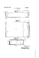
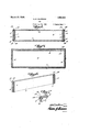
- FIG. 1 is aside elevation of a box const-ructed in accordance with my invention
- Fig. 2 is a top plan view, parts being broken away and illustrated in cross section,
- Fig. 3 is an endelevation
- Fig. 4 is a longitudinal sectional view
- Fig. 5 is an enlarged transverse sectional view, taken on the line 5-5 of Fig. 1,
- Fig. 6 is a detailed perspective view of one of the side members, and V Fig. 7 is a section'on the line 77 of Fig. 3.
- top 4 and end pieces 5 are all made as separablemen'ibers.
- the side walls 2 and 3 of the box are provided with spaced cleats 6 and 7 at the ends thereof with the endsof the cleats 6 cut off so as to be remote from the top and bottom edges of the side walls.
- the bottom member 1 has transverse cleat 8 at each end thereof fitting against the lower ends of the cleatsG as is illustrated in Fig. l.
- the ends 5 of the box are fitted into the space between the cleats 6 and 7 so as to securely retain them against lateral movement and theouter face thereof abuts against the cleats '8.
- the bottom or top member 4 is provided with endcleats 9 which rest upon the upper ends of the cleats 6 so that when the top, bottonnends and sides are fitted together as shown in Fig. 4, the several par'tswill be closely fitted together and the cleats so positioned relative to each-other as to prevent lateral or longitudinal movement of any of the parts.
- a metal strip 10 extendsentirely around the box at each end thereof and these strips are fitted onto the shoulders 11 formed by the cutting away of a portion of each end of the box and the shoulders are provided with bevelled portions 12 whereby the strips may be readily placed in position.
- the strips extend across the upper edge of the end pieces so as to securely retain the end pieces in spaced relation with the cover when same is removed from the box.
- a box structure including a body comprising bottom, side, and end portions, spaced cleats secured to the side members adjacent the ends thereof, the cleats disposed toward the ends being of shorter length than those disposed away from the ends, cleats secured to a cover member and the bottom member and adapted to rest upon the ends of the shorter of the cleats, said end members being adapted to be slidably positioned'between the spaced cleats with their lower edge portions abutting the cleats of the bottom member, said side and bottom members having portions cut from one face thereof adjacent the ends adapted to provide shoulders, connecting bands each having end portions secured together and arranged for connecting the end members, side members,.:and bottom member in distended position, and bands connected to the side members fitting over beveled edges on the cover member for connecting the cover to the box when in distended position.
Landscapes
- Engineering & Computer Science (AREA)
- Life Sciences & Earth Sciences (AREA)
- Wood Science & Technology (AREA)
- Mechanical Engineering (AREA)
- Packging For Living Organisms, Food Or Medicinal Products That Are Sensitive To Environmental Conditiond (AREA)
Description
Patented Mar. 20, 1928.
UNITED STATES PATENT OFFICE. l
AQUILLER D. CLAWSON, or cnIcAG iLLnvoIs;
7 Application filed June 24, 1925. Serial No. 39,858.
This invention relates to new and useful improvements in boxes andmore particular- 1y to a collapsible box. The main object of my invention is the provision of a collapsible box whereby the same may be quickly and readily taken apart and placed incompact form so as to occupy a minimum spacewhen not in use and at the same time can be readily set up'ready for use.
One of the principal objects of my invention is the provision of a box which. is especially adapted for use in meat packing plants wherein the 'meat is laced in boxes prior to beingplaced in a refrigeration plant and in this process the boxes are usually'destroyed iuorder to remove the meat therefrom, but with the use of my improvedcollapsible box, the sides, top and bottom andend walls may be readily taken apart so that the meat can be removed from the box when desired with out destroying the box itself.
A further object of my invention is the provision of a box of the above character wherein removable means is employed for retaining the box in its operative posit-ion and for clamping the cover in position on the box until it is desired to disassemble the same. a
With the above and other objects in view, my invention consists in the novel features of construction and the combination and arrangement of parts to be hereinafter more fully described, pointed out in the claim and shown in the accompanying drawings, in which:
Fig. 1 is aside elevation of a box const-ructed in accordance with my invention,
Fig. 2 is a top plan view, parts being broken away and illustrated in cross section,
Fig. 3 is an endelevation,
Fig. 4 is a longitudinal sectional view,
Fig. 5 is an enlarged transverse sectional view, taken on the line 5-5 of Fig. 1,
Fig. 6 is a detailed perspective view of one of the side members, and V Fig. 7 is a section'on the line 77 of Fig. 3. I
In carrying out my 1, sides 2 and 3, top 4 and end pieces 5 are all made as separablemen'ibers. The side walls 2 and 3 of the box are provided with spaced cleats 6 and 7 at the ends thereof with the endsof the cleats 6 cut off so as to be remote from the top and bottom edges of the side walls. 1
yokes have their ends pivotall invention, the bottom The bottom member 1 has transverse cleat 8 at each end thereof fitting against the lower ends of the cleatsG as is illustrated in Fig. l.
The ends 5 of the box are fitted into the space between the cleats 6 and 7 so as to securely retain them against lateral movement and theouter face thereof abuts against the cleats '8. The bottom or top member 4; is provided with endcleats 9 which rest upon the upper ends of the cleats 6 so that when the top, bottonnends and sides are fitted together as shown in Fig. 4, the several par'tswill be closely fitted together and the cleats so positioned relative to each-other as to prevent lateral or longitudinal movement of any of the parts.
In order to retain the several sections of the box in set-up position, a metal strip 10 extendsentirely around the box at each end thereof and these strips are fitted onto the shoulders 11 formed by the cutting away of a portion of each end of the box and the shoulders are provided with bevelled portions 12 whereby the strips may be readily placed in position. It will be noted that the strips extend across the upper edge of the end pieces so as to securely retain the end pieces in spaced relation with the cover when same is removed from the box. When the box is set up ready for use the same is packed with meat or any other material and the cover then placed in position with the cleats 9 fitting into the upper ends of the cleats 6 and U shaped yokes 13 are provided for retaining the cover in position. These connected to the side portions of the strips 10 as is clearly shown in Fig. 5, so that the intermediate portions of the U shaped yokes may be swung upwardly and engaged over the top of the box as shown in Fig. 5, the ends of the top member being bevelled as indicated at l to permit the intermediate portions of the yokes to be fitted into clamping engagement with the top.
From the above it will be apparent that I have provided a simple and inexpensive box of the character set forth wherein the parts of the, box are so arranged that the box may be quickly disassembled and at the same time readily set up for use. Thus it will be apparent that in using this construcends thereof after the cover or top has been purposes.
lVhil-e I have shown and described the preferred form of my invention, it Will be obvious that various changes in the details of construction and the arrangement and proportions may be resorted to for successfully carrying my invention into practice Without departing from the scope of the appended claim.
Having thus described my invention, what I claim is:
A box structure including a body comprising bottom, side, and end portions, spaced cleats secured to the side members adjacent the ends thereof, the cleats disposed toward the ends being of shorter length than those disposed away from the ends, cleats secured to a cover member and the bottom member and adapted to rest upon the ends of the shorter of the cleats, said end members being adapted to be slidably positioned'between the spaced cleats with their lower edge portions abutting the cleats of the bottom member, said side and bottom members having portions cut from one face thereof adjacent the ends adapted to provide shoulders, connecting bands each having end portions secured together and arranged for connecting the end members, side members,.:and bottom member in distended position, and bands connected to the side members fitting over beveled edges on the cover member for connecting the cover to the box when in distended position.
In testimony whereof I affix mysignature.
AQUILLER D. CLAVVSON
Priority Applications (1)
| Application Number | Priority Date | Filing Date | Title |
|---|---|---|---|
| US39358A US1663441A (en) | 1925-06-24 | 1925-06-24 | Box |
Applications Claiming Priority (1)
| Application Number | Priority Date | Filing Date | Title |
|---|---|---|---|
| US39358A US1663441A (en) | 1925-06-24 | 1925-06-24 | Box |
Publications (1)
| Publication Number | Publication Date |
|---|---|
| US1663441A true US1663441A (en) | 1928-03-20 |
Family
ID=21905044
Family Applications (1)
| Application Number | Title | Priority Date | Filing Date |
|---|---|---|---|
| US39358A Expired - Lifetime US1663441A (en) | 1925-06-24 | 1925-06-24 | Box |
Country Status (1)
| Country | Link |
|---|---|
| US (1) | US1663441A (en) |
Cited By (1)
| Publication number | Priority date | Publication date | Assignee | Title |
|---|---|---|---|---|
| US2598616A (en) * | 1949-08-24 | 1952-05-27 | Sterner Olof Fredrik | Crate for eggs or other similar piece goods |
-
1925
- 1925-06-24 US US39358A patent/US1663441A/en not_active Expired - Lifetime
Cited By (1)
| Publication number | Priority date | Publication date | Assignee | Title |
|---|---|---|---|---|
| US2598616A (en) * | 1949-08-24 | 1952-05-27 | Sterner Olof Fredrik | Crate for eggs or other similar piece goods |
Similar Documents
| Publication | Publication Date | Title |
|---|---|---|
| US2091126A (en) | Container | |
| US3006496A (en) | Collapsible container | |
| US1663441A (en) | Box | |
| US2566500A (en) | Packing box | |
| US1887406A (en) | Knock-down hogshead | |
| US1636223A (en) | Collapsible packing case | |
| US1818266A (en) | Box cover | |
| NO844972L (en) | PROCEDURE FOR FREEZING FORMABLE FOOD PRODUCTS FOR AA THANKS, AND A FREEZING FOR IMPLEMENTATION OF THE PROCEDURE | |
| DE437127C (en) | Cutting device for fruits, vegetables u. like | |
| US2921729A (en) | Cardboard berry box | |
| US2826968A (en) | Die for cutting box blanks | |
| US1759592A (en) | Retainer for sliced bread | |
| US1586898A (en) | Method of freezing and transporting perishable food products | |
| DE732529C (en) | Method for closing the open ends of polygonal containers made of cardboard, paper or the like. | |
| US1806437A (en) | Blade sharpener | |
| US396138A (en) | Fruit-box | |
| US1680905A (en) | Method of and means for sealing receptacles | |
| US1477542A (en) | Packing guide for fruit and vegetable containers | |
| US2048873A (en) | Plant package | |
| DE599783C (en) | Sealing sleeve for the overlapping ends of a band tire for packages, z. B. boxes or bales | |
| US2014252A (en) | Combination receptacle and cutting guide | |
| DE826488C (en) | Locking and carrying device for packaging containers | |
| US1874317A (en) | Fruit basket collar | |
| US2130616A (en) | Display device | |
| US1967146A (en) | Method of making baskets |