US1663407A - Desk - Google Patents
Desk Download PDFInfo
- Publication number
- US1663407A US1663407A US114340A US11434026A US1663407A US 1663407 A US1663407 A US 1663407A US 114340 A US114340 A US 114340A US 11434026 A US11434026 A US 11434026A US 1663407 A US1663407 A US 1663407A
- Authority
- US
- United States
- Prior art keywords
- body portion
- support
- receptacles
- pair
- desk
- Prior art date
- Legal status (The legal status is an assumption and is not a legal conclusion. Google has not performed a legal analysis and makes no representation as to the accuracy of the status listed.)
- Expired - Lifetime
Links
Images
Classifications
-
- A—HUMAN NECESSITIES
- A47—FURNITURE; DOMESTIC ARTICLES OR APPLIANCES; COFFEE MILLS; SPICE MILLS; SUCTION CLEANERS IN GENERAL
- A47B—TABLES; DESKS; OFFICE FURNITURE; CABINETS; DRAWERS; GENERAL DETAILS OF FURNITURE
- A47B17/00—Writing-tables
- A47B17/02—Writing-tables with vertically-adjustable parts
-
- A—HUMAN NECESSITIES
- A47—FURNITURE; DOMESTIC ARTICLES OR APPLIANCES; COFFEE MILLS; SPICE MILLS; SUCTION CLEANERS IN GENERAL
- A47B—TABLES; DESKS; OFFICE FURNITURE; CABINETS; DRAWERS; GENERAL DETAILS OF FURNITURE
- A47B2220/00—General furniture construction, e.g. fittings
- A47B2220/0002—Adjustable furniture construction
- A47B2220/0013—Table or cupboards with upwardly concealable compartments
Description
March zo, "1928. J. A.` HUGHES' 1663407 M23 vm $326 7?] 4 sneetgsheeu wwwlllgh'llmll um jNI/ENTOR.
l i I March 20, 1928.
J. A. HUGHES DESK Filed June '7. 1926 4 Sheets-Sheet 2 lBY , ATToRNEY.
` March 20, 1928.
1,663,407 'J. A. HUGHES Filed June 7- 1926 4 Sheets-Sheet 4 typistsusewhen the top isy Vshifted lfrom Patented Mar. 20, 1928.
UNITED STATES JOHN A. HUGHES, ior Waco, mixes.
DESK.
Appneanon' med :une 7,
.ary body portion and a shift-able #top 'therelfor constituting means for normallyclosing the upper end of said body portion, and with the latter provided with means for supporting a -typewriterin position tor a closure position and tor-concealing the typewriter when the top is -shifted to closure position, and further providing the desk with a pair of vertically movable receptacles carrying supplies or other articles for the typist and with such receptacles shittable synchronously `with the typewriter support to a position in convenient 'reach' of the typistwhen the top is moved from lclosure position and concealed by the `top when the latter is in closed position with lrespect'to the body portion of the desln A further object of the invention is to provide, in a manner as hereinafter set forth a desk oi the class described, including a body portion, a shittable top therefor, fa shiitable typewriter carrier or support connected with the body portion, a pair of shiftable receptacles, and alink and lever mechanism connected tothe -body portion and vto said top i'or shifting said carrier to expose and conceal the typewriter on the opening and closing of the top and further to 'position said receptacles in convenient reach of the typist.
Further objects of the invention Jare' to provide, in amanncr as hereinafter set forth, a combination typewriterV `and cabinet desk which is comparatively simple in its construction and arrangement, strong, durable,
conveniently shifted to open and closed position, thoroughly eilicientin its use, readily assembled, and comparatively inexpensive to manufacture.
lilith the foregoing and other objectsin view, the invention consists ofthe novel construction, combination and arrangement of parts as hereinafter more specifically described, and illustrated in the accompanying drawings, wherein is shown an embodiment ot' the invention, but it is to be understood that changes, variationsnnd niodiiications can be resorted to which fall within the scope ot the claims hereuntoappended.
'same closed.
Figure 5 is a sect-ion on 1928. Serial No. 114,340.
In the drawings wherein like reference vcharacters denote corresponding parts throughout the several views:
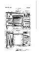
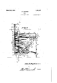
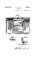
Figure l is a frontl elevation of a combination 'typewriter and cabinet `deskin accordance with this invention and withk the Figure 2 is a section on line 2'-2, Figure.k "a
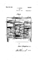
` FigureB'is a section on line 3-3, Figure': with the desk open.` Y 1 "Figure 4 is a section on line 3f-4, Figure 2 with the desk open.` A
line y5--5,jl*`igi`1re'8. Figure 6 lis a section on line 6-6, Figure 4. Figure 7 is a sectionaldetail.
f The combination typewriter and cabinet desk, in accordance witli'thisiinvention, comprises a ybody portion, a shittable top therefor, a typewriter support or carrier pivotally connected to and withinv said body portion,
a pair of superposed filing trays carried by ,the "body portion and ,with the upper `tray .Ishiftable relative tothe lower tray, 'an 'open top file case arranged in parallelism with and opposing saidv trays and carriedby the body portion, means Vto provide a 'combined arm rest and closure for the open top of the upper tray, a pair of vertically shiftable compartment receptacles mounted in the body portion, and a link and lever mechanism to `provide for the synchronous shitting of the top, support and compartment receptacles on the opening and` closing of the desk.
The body portion includes a 'pair of drawer sections referred to generally bythe reference charactersl and 2 and which are of `rectangular contour and arranged `in spacedfrelation. Each of said sections is providedk with a pair of drawers 3, 4 arranged in superposed relation and with the upper drawer 3 spaced a substantial distance ,the section l and terminates at a point removed therefrom and abuts a vertically dis posed partition member 6 spaced rfrom the rear end of the section l. The vpartition in connection with the partition 6 as well as fthe sidesk and lfront of the section lfvform an Atromthe top of its respective drawer'section.
end wall of the tray 11.
open top le case 7. The partition 6 in connection with the rear end of the section 1 forms a vertically disposed space 8 in which is arranged a vertically movable compartment receptacle 9.
The section 2 in proximity to the drawer 3 thereof is provided with a partition 10 forming a tray 11 having the front wall 12 thereof of greater height than its side and end wall. Arranged upon the side walls of the tray 11 and rearwardly with respect to the front wall 12 of the latter is a tray 13. r1`he end walls of the tray 13 are indicated at 14, 15 and which are connected to the end walls of the tray 11 by a pair of links 16, 17..
Each pair of links has its upper end connected to an end wall of the tray 13 and to an The two pair of links provide means whereby the tray 13 can be shifted laterally with respect to the tray 11 and suspended. Each link 16 has a curved lower end as indicated at 18 in Figure 2.v The section 2 is furthermore pro- .rear end of said section 2 forms a passage 20 for a vertically shiftable compartment re* ceptacle 21. The compartment receptacle 9, as well as the receptacle V21 is of less height than the height of either one of said sections 1 or 2. Each of said receptacles has a beveled top as indicated at 22 in Figure 3. The compartment receptacles are provided for receiving typists supplies such as stationery, envelopes, etc. The rear end of the sections 1 and 2 are formed by a back 23, see Figures 4 and 5 and which acts to maintain the sections 1 and 2 in spaced relation at the rear thereof. The sections 1 and 2 at the top thereof are connected together by an angle iron 24 formed of a vertical and a horizontal leg and with the latter indicated at 25 and projecting rearwardly from the lower end of the vertical leg. The sections 1 and 2 are supported by a rear pair of supporting legs 26 and a front pair of supporting legs 27. The partition 19 is spaced from the rear end of the trays 11 and 13 and also the rear ends of the drawers 3 and 4 of the section 2 to provide a space 28.
Arranged in the space 28, seek Figures 2,
3 land 5. is a panel 29 provided at its lower 'end with a pair oflateral lugs 30 and the upper end of said panel 29 is formed with a curved terminus 31, see Figure 3. Secured to the inner face of each side wall of the section 2, at the up er end thereof is a curved bracket 32, see igure 7, and which is engaged by the lugs 30 thereby providing a ulcrum for the panel so that the panel can assume a position to close the tray 11 and also to constitute an arm rest. The lugs 30 coact with the bracket 32 to prevent the withdrawal of the panel from the section 2, that is to say the complete withdrawal of thepanel.v When the panel 29 is in its vertical or non-active position the curved terminal portion 31 thereof engages over the end wall of the tray 11, see Figure 7.
The shiftable top, which is referred to generally by the reference character 33 is in the form of a rectangular hood open at its rear and consisting of a top wall 34, a front wall 35 having its intermediate portion 36 of greater height than its end portion, and a pair of side walls 37, 38 of the same height as the height of the end portions of the front wall 35. The intermediate portion 36 of the front wall 35 is of greater length than the width of the space between the sections 1 and 2 of they body portion of the desk whereby when the top is in closed position the end terminal portions of theV intermediate portion 36 and the front wall 35 will extend at the front of the sections 1 and 2 of the body portion of the desk. When the top 33 is shifted to open position it extends vertically and the wall 34 is arranged rearwardly of the back 23 of the body portion, see Figure 3.
Secured to the back 23, on its forward face, at itsvertical median and near its top is a combined guide and keeper 39 which is vertically disposed. Secured to the forward face of the back 23 and spaced from the inner wall 40 of the section 1 is la` vertically disposed guide member 41. Securedto the forward face of the back 23 and spaced from thekinner wall 42 of the section 2 is a vertically disposed guide member 43. The guide members 41 and 43 extend from the lower edge of theback 23 and terminate at a point below the top edge thereof. The guide member 41 is oppositely disposed with respect t0 the guide member 43. Each of the guide members is constructed in a manner as shown in Figure 6 and is formed of a pair of end portion-s 44, 45 and an intermediate portion 46. The end portion 45 is offset with respect to the end portion 44. The end portion 44 is secured to the back 23 and the end portion 45 spaced from the back 23 to provide a guide passage 46. The construction as set forth with respect to guide member is when a guide member is in transverse -section as shown in Figure 6. The hold fast devices for {ixedly securing the guide members to the back 23 are indicated at 47. The side wall 40 of the section 1 is formed with a vertically disposed slot 43 and the side wall 42 of the section 2 is formed with a vertically disposed slot 49 which opposes the slot 43. The function of the slots 48 and 49 will bc presently rcferred to. The combined guide and keeper 39, guide members 41 and 43 and slots 4Q. and 49 are associated with the link and lever mechanism which coacts to provide for the synchronous shifting of the top 37, the tjxpcwriter support or carrier t0 be presentlyv rel (Ni from the back 23.
ferred to yand the vertically movable compartment receptacles.
The typewriter support or carrier is referred to generally by the reference character 56 and is arranged in the space formed between the sections l and 2 ofthe body portion. -Tlic support 50'extends from the front end of the space between the sections 1 and 2 and terminates at a point removed The forward portion of the support 50, as indicated at 51, is of the saine width as the width of the space be` tween the sections l and 2 of the body portion, but the rear portion ofthe support 50,
v as indicated at 52 is of'less width than the width of the space between the sections 1 and 2, see Figure 5. The cutting away of the rear part 52 of the support 56 provides a clearance when the latter i-s shifted to and from supporting position r rather when the latter is shifted to and from active and iiiactive position to expose and conceal a typewriter, not shown, secured to said support. W'hen the support 50 is shifted for the purpose of positioning ar typewriter for conveiiient access thereto by a. typist, the support assumes a horizontal position and its forward end is mounted on the horizontal leg of the angle iron 24. see Figure 3. The support 50 is provided with a* depending iange 53 which is coeXtensive therewith. Depending from the flange 53 atcach side thereof vand in proximity to its forward end, is a hanger 54. The inner walls and 42 of the lsections 1 and 2 respectively, are provided with stub shafts 55, see Figure 3, upon which the hangers 54 are pivotally mounted. lhen thesupport is shifted to expose the-typewriter. it will be in the position as shown in full lines in Figure 3 and when shifted to a position to conceal the typewriter it will be as indicated in dotted lines in Figure 3. c
The link and lever mechanism which coacts with the top 33, compartment recepf tacles 9 and 2O and support 50 includes a pair of slidable hinges for the top 33 and which are coupled together by an actuating means for a pair of oppositely disposed shifting devices for said receptacles 9 and 20. Said mechanism further includes a pair of elevating and lowering devices for the support 50 and a manually operated actuating means for said mechanismf The slidable hinges which associate with the top 33 are indicated generally by the reference characters 56, 57. As each yof the hinges areof the same construction, but one will be described, as the description of one will apply to the other.
the opposed ends pivotally connected together as at 60. The section 58 is of materially greater length than the section 59 and the upper terminal portion of the sec- Each of said hinges' consists of a pair of sections 58.v 59 having tion 58 is inset as at 61 and iixedly secured to the wall 34 of the top 33 as at 62. The insetting of the terminal portion 61 ofthe section 58 provides for they niajorportion of said section to be offset with respect to the portion 6l thereby permitting of the back 23, when the top is shifted, to slide between the wall 34 of the top 33 and the sections 58 of the hinges and in this connection see Figure 3. The hinge-s 56 and,` 57 slide between the guide members 41, 43'respectively and the walls 40, 42 respectively and in this connection see Figure 4. The section 59 of the hinge at its lower end is `formed lwith a laterally extending lug63 which rides in the guide passage v46, see Figure 6. Also Isee Figure 4. To yprevent the separation of the hinges 56 and 57 with respect to the guide members 41, 43 stop lugs 64 are secured to the back 23 and posi tioned at the upper ends of the guide passages 46 and in this connection see Figure' 4. The hinges 56 and 57 are connected together to provide for the Isynchronous movement thereof through the medium ofa coupling bar 65, which isconnected at one end as at 66 to the hinge 56 and at its other end as at 67 to the hinge 57. The coupling bar also provides' means for actuating the pair of oppositely disposed shifting de vices for the compartment receptacles 9 and 20. f
As the pair of oppositelyl disposed shifting devices for the compartment receptacles 9 and 2O are of the same construction, but one willybe described, as the description of one will apply to the other. Each of said `devices'consists of alever arm 68 pivotally i connected, as at 69 to a guide member 41 or 43. The lever arm- 68 extends through a slot 48 or 49 and has its inner end pivotally connected as at 69 to a vertically disposed link 70 which is pivotallyconnected as at 71, to a hanger 73 which depends from the bottom of a compartment receptacle'and in this connection see Figure 4. The outer end of the lever 68 is pivotally connected as at 7 3 to the lower end of an upstanding link 74. Slidably mounted in the combined Vguideaiid keeper 39 is a shifting member 75 which is common tol the pair of oppositely dis-y posed shifting devices for the compartment receptacle and said shifting member 75 has its lower end provided with a nose 76.. The upper ends of the links 74 of the said shifting devices, areY pivotally connected to a common pivot 77 carried by the' member 75 above the nose 7 6. The nose 76' of the member 75 is in the-path of the coupling bar 65 so that when the latter moves downwardly the member 65will be carried therewith. and under such conditions moving the lilik 74 downwardly and shifting the levers 68 on their pivots, whereby the'innerl ends of the levers will assumev the full line position lli shown in Figure Il: and elevate the compartment receptacles 9 and 20. vWhen the hinges 56 and 57 move upwardly, carrying the bar therewith, the receptacles 9 and 2O will .move downwardly by gravity, whereby the lever arn'i`s`68 will assume the dotted line position shown in Figure il. The compartment receptacles 9 and 2O are moved upwardly to the position shown in Figure 1- when the top 33 is swung` to open position and the upward movement et the receptacles is caused by the swinging ot the levers 63 due to the engagement o t the bar G5 with the nose carriedV at the lower end ot the meinber 75, but as before stated the lowering movement ot said receptacles is caused by gravity.
As the pair ot elevating and lowering devices 'for the support 50 are ot the same construction, but one will be described, as the description of one will apply to the other. Each of said elevating and lowering devices comprising a depending link 73, which is .pivotally connected at its upper end as at 79 to one side ot the flange 53 and said link 78 has its lower end pivotally connected as at 80 to the upper end ot a lever arm 8l., the latter being pivoted between its transverse median and its upper end, as at 32 upon a pivot extending from the inner wall of the sections 1 or 2 ot the body portion and in this connection see Figure 3. The lower end ot the lever arm 81 is pivotally connected as at 83 to the lower end ot an upsta-nding link 84, the latter having its upper end pivotally connected as at S5 to a hinged section 59, and in this connection see Figures 3 and 4. lhen the top 33 is swung to open position, so as to be disposed vertically7 with respect to the body portion ot the desk, and as shown in Figure 3, the position of each elevating and lowering device will be as indicated in full line in Figure 3 whereby the support 50 will be disposed horizontally with respect to the body portion of the desk. When the top 33 is shifted to closure position, with respect to the body portion ot the desk, each elevating and lowering device for the support 50 will be in the position as indicated 'in dotted lines in Figure 3. 1When the support 5() is lowered to conceal the typewriter, it will be as shown in dotted lines in Figure 3.
rllhe manually actuated operating means for the link and lever mechanism comprises a yoke shaped member 36 having its arms pivoted as at 87 to the inner walls ot the sections 1 and 2. Pivotally connected as at 38 to each arm ot the member 36, is the lower end oit a link 89 and said link 89 has its upper end pivotally connected as at 90, to a lever arm 91, which is pivotally connected as at 92 to an inner wall ot the section 1 or 2 of the desk body. The pivot 39 is disposed between the vertical median of the Locate? lever arm 91 and its rear end. The forward end of the lever arm 91 is pivotally connected to the lower end ot an upstanding rear- `wardly inclined link 93 which has its upper end pivotally connected. as at 94, to the lever arm 81 below the pivot 82 for the latter.
By operating the member 86 in the manner so that it will assume the dotted line position shown in Figure 3, the to-p 33 will be shifted upwardly so it can be grasped and moved to the full line position shown in Figure 1. The member 8G is operated by toot pressure. The top 33 is shifted toJ open position manually, that is to say it is started and the weight thereof will assist it to assume the vertical position shown in Figure 3. A suitable locking means indicated at 95, Figure 1 can be employed for securing the top 33 in closed position. When the top is shifted to the position shown in Figure 3, the weightthereot will maintain the top in full line position so that the support will be retained in its horizontal position to prevent the shitting thereof when the typist is operating on the typewriter mounted on said support 50. The top 33 further provides a closure 'tor the tray 13 and filing case 7. When the top is shifted to open position the compartment receptacles are moved so that they will be in convenient access to the typist and furthermore as the tile case 7 and trays are arranged at each side of the support 50 they will also be in convenient reach of the typist.
t is thought the many advantages of a combination typewriter and cabinet desk, in accordance with this invention can be readily understood, and although the preiterred embodiment ot the invention is as illustrated and described, but it is to be understood that changes in the details of construction can be had which will tall within the scope ot the invention as claimed.
What l claim is:
1. A desk ot the type described comprising a body portion. a shittable typewriter support arranged within the latter, a pair of spaced, vertically movable open top recepta cles arranged within the body portion atthe rear thcreot. a shittable hinged top common to said receptacles and body portion, and slidably connected to the front ot the back oit the latter, and a link and lever mechanism pivotally connected with said top, support and receptacles and slidably and pivotally connected. to said body portion to provide for the synchronous shitting ot the support and receptacles to open and closed positions on the opening and closing of said top respectively.
Q. A. desk of the type described comprising` a body portion, a pair of spaced, vertically movable open top receptacles arranged within said body portion, a shittable hinged top common to said receptacles and body portion and slidably connected to the front of the back'of thelatter and a lin and lever mechanism vpivotally connected withfsaid top and receptacles and slidably and pivotally connected to said body portion to provide for the synchronous shifting of said receptacles to open and closed positions on the opening and closing of said top respectively.
V3. A ydesk of the type described comprising a body portion, a pair of spaced, vertically movable openv top receptacles arranged within said body portion, a shiftable hinged top common to saidreceptacles and body portion, means for slidably connecting said top to the front of the back of the body portion, andV a link and lever mechanism pivotally connected with said top and receptacles and slidably and pivotally connected to said body portion to provide for the synchronous shitting of saidy receptacles to open and closed positions on the opening andy closing oi' said top respectively.
l. A desk of the type described comprising a body portion, a sliiftable hinged top for normally closing said body portion, a
pair of hinges connected to said top andslidably connected to the back of said body portion, a shiftable typewriter support arranged within the body portion, and a link and lever mechanism connected to said support and to said hinges to provide for the shifting of said support to open and closed positions on the opening and closing of said top respectively.
5. A desk of the type described comprising a body portion, a shiftable hinged top for normally closing said body portion, a.
pair of hinges connected to said top and slidably connected against the forward face of the back of said body portion, saidhinges offset to overlap the back of the body portion, a shii'table typewriter support arranged within the body portion, and a. link and lever mechanism connected to said support, body ortion and hinges to provide for the shifting of said support to open and closed positions on the opening and closing of said top respectively. f
6. A desk of the type described comprising a body portion, a manually shiftable,
hinged top slidably connected to the front said body portion and providingmeansffor normally closing the upper part of thebody portion, a shiftable typewriter supportarranged wit-hin the body portion, a linkl and lever mechanism connected with said vbody portion, top and support for shifting ,the supportto open and closed positions on ,the opening and closing of said top respectively, anda manually operated yoke shaped member connected to said body portionand mec anism ior actuating thelatter'tofinitially start the top to closed position.
8. A deskothe type described comprising a body portion including a back and a pair of drawer sections spaced from each other, said body portion having an open upper end, a manually shiftable hinged top slidably connected to the forward face of the back of said body portion and providing means for normally closing the upper part of the body portion, a shiftable typewriter support arranged between said drawer sections, alink and lever mechanism connected to said drawer sections, top and support for shifting the support to open and closed positions on the opening and closing of said hingedl top respectively, and a manually operated means arranged between said drawer sections, connected therewith and to said mechanism for actuating the latter to initially start the top to closed position.
9. A desk of the type described comprising a compartment body portion, a shiftable typewriter support arranged within the latter, a pair of spaced vertically movable open top receptacles positioned within the body portion and arranged rearwardly of said support, a shiftable top for enclosing the upper end of said body portion and providing a closure common to said receptacles, means for slidably connecting the top to the front of the back of the body portion and providin a hinge for the top, and
means pivotal y connected to said slidable connection,` slidably and pivotally connected t-o said body portion and pivotally connected to said support and receptacles to provide for the synchronous shifting of the support and receptacles to open and closed positions on the opening and closing of said top respectively with respect to the upper end of said body portion.
10. A desk of the type described comprising a compartment body portion, a shiftable typewriter support arranged within the latter, a pair of vertically movable open top receptacles positioned within the body portion and arranged rearwardly of said support, a shiftable hinged top for enclosing the upper end of said body portion, means connected to said top, body portion, support and receptacle to provide for the synchronous shifting of the vsupportand receptacles to open and closed positions on the opening movable open top receptacles" positioned at the rear of each of said sections, a shiftable hinged top slidably connected to said back and common to said receptacles and body portion, and a link and lever mechanism connected with said top, support, sections and receptacles to provide for the synchronous shifting of the support and receptacles to opened and closed positions on the opening and closing ot said top respectively.
In testimony whereof, I aiix my signature hereto. e
JOHN A. HUGHES.
Priority Applications (1)
| Application Number | Priority Date | Filing Date | Title |
|---|---|---|---|
| US114340A US1663407A (en) | 1926-06-07 | 1926-06-07 | Desk |
Applications Claiming Priority (1)
| Application Number | Priority Date | Filing Date | Title |
|---|---|---|---|
| US114340A US1663407A (en) | 1926-06-07 | 1926-06-07 | Desk |
Publications (1)
| Publication Number | Publication Date |
|---|---|
| US1663407A true US1663407A (en) | 1928-03-20 |
Family
ID=22354649
Family Applications (1)
| Application Number | Title | Priority Date | Filing Date |
|---|---|---|---|
| US114340A Expired - Lifetime US1663407A (en) | 1926-06-07 | 1926-06-07 | Desk |
Country Status (1)
| Country | Link |
|---|---|
| US (1) | US1663407A (en) |
-
1926
- 1926-06-07 US US114340A patent/US1663407A/en not_active Expired - Lifetime
Similar Documents
| Publication | Publication Date | Title |
|---|---|---|
| US2254431A (en) | Medicine cabinet | |
| US2119313A (en) | Cosmetic case | |
| US2672384A (en) | Fold-away cabinet table | |
| US2031287A (en) | Wall table | |
| US2383831A (en) | Combination extension table and chair | |
| US2323107A (en) | Office desk | |
| US1663407A (en) | Desk | |
| US1179017A (en) | Folding sewing-cabinet. | |
| US3762675A (en) | Cookbook stand construction | |
| US1448788A (en) | Combined dresser and table | |
| US2316756A (en) | Typewriter desk | |
| US2082672A (en) | Foldable and extendible drawer structure | |
| US3306690A (en) | Sewing machine cabinets | |
| US1485549A (en) | Typewriter desk | |
| US2820686A (en) | Portable lectern | |
| US2015518A (en) | Article of furniture | |
| US1877470A (en) | Telephone cabinet | |
| US2265565A (en) | Vanity cabinet | |
| US2401526A (en) | Cabinet and machine support | |
| US1565247A (en) | Cabinet desk | |
| US2004896A (en) | Folding furniture | |
| US2561681A (en) | Cabinet | |
| US1698981A (en) | Folding dressing table | |
| US1533219A (en) | Combination furniture | |
| US2316717A (en) | Luggage |